Operating Instructions MxxMA-MxERA Three-phase AC ... - Lenze
Operating Instructions MxxMA-MxERA Three-phase AC ... - Lenze
Operating Instructions MxxMA-MxERA Three-phase AC ... - Lenze
Create successful ePaper yourself
Turn your PDF publications into a flip-book with our unique Google optimized e-Paper software.
Mechanical installation<br />
Spring−applied brakes<br />
5<br />
5.5 Spring−applied brakes<br />
Important notes<br />
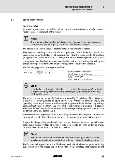
As an option, the motors can be fitted with a brake. The installation of brakes (in or on the<br />
motor) increases the length of the motor.<br />
Note!<br />
The brakes used are not fail−safe because interference factors, which cannot<br />
be influenced (e.g. oil ingress), can lead to a reduction in torque.<br />
The brakes serve to hold the axes at standstill or in the deenergised state.<br />
They operate according to the closed−circuit principle, i.e. the brake is closed in the<br />
deenergised state. The brakes for DC supply can be fed with a bridge−rectified DC voltage<br />
(bridge rectifier) or with a smoothed DC voltage. The permissible voltage tolerance is 10 %.<br />
If long motor supply cables are used, pay attention to the ohmic voltage drop along the<br />
cable and compensate for it with a higher voltage at the input end of the cable.<br />
The following applies to <strong>Lenze</strong> system cables:<br />
U* U B 0.08<br />
m L I B<br />
U* [V] Resulting supply voltage<br />
U B [V]<br />
l [m]<br />
I B [A]<br />
Rated voltage of the brake<br />
Cable length<br />
Rated current of the brake<br />
Stop!<br />
If the brake is not supplied with the correct voltage (see nameplate), the brake<br />
is applied and may be overheated and destroyed by the motor that possibly<br />
continues to rotate.<br />
The shortest operating times of the brakes are achieved by DC switching of the voltage and<br />
a suppressor circuit (varistor or spark suppressor). Without suppressor circuit, the<br />
operating times may increase. A varistor/spark suppressor limits the breaking voltage<br />
peaks. It must be ensured that the power limit of the suppressor circuit is not exceeded.<br />
This limit depends on the brake current, brake voltage, disengagement time and the<br />
switching operations per time unit.<br />
Furthermore, the suppressor circuit is necessary for interference suppression and also<br />
increases the service life of the relay contacts (external, not integrated in the motor).<br />
For permissible operating speeds and characteristics, please see the respective valid motor<br />
catalogue. Emergency stops at higher speeds are possible, but high switching energy<br />
increases wear on the friction surfaces and the hub.<br />
Stop!<br />
The friction surfaces must always be free from oil and grease because even<br />
small amounts of grease or oil will considerably reduce the braking torque.<br />
The formula below provides a simplified way to calculate friction energy per switching<br />
cycle which must not exceed the limit value for emergency stops that depends on the<br />
BA 33.0005−EN 2.0<br />
29


