Operating Instructions MxxMA-MxERA Three-phase AC ... - Lenze
Operating Instructions MxxMA-MxERA Three-phase AC ... - Lenze
Operating Instructions MxxMA-MxERA Three-phase AC ... - Lenze

You also want an ePaper? Increase the reach of your titles
YUMPU automatically turns print PDFs into web optimized ePapers that Google loves.
Maintenance/repair<br />
Maintenance operations<br />
Spring−operated brakes<br />
8<br />
Wear on spring−applied brakes<br />
The used spring−applied brakes have a low rate of wear and are designed for long<br />
maintenance intervals.<br />
However, the friction lining, the teeth between the brake rotor and the hub, and also the<br />
braking mechanism are naturally subject to function−related wear which depends on the<br />
application case (see table). In order to ensure safe and problem−free operation, the brake<br />
must therefore be checked and maintained regularly and, if necessary, replaced (see brake<br />
maintenance and inspection).<br />
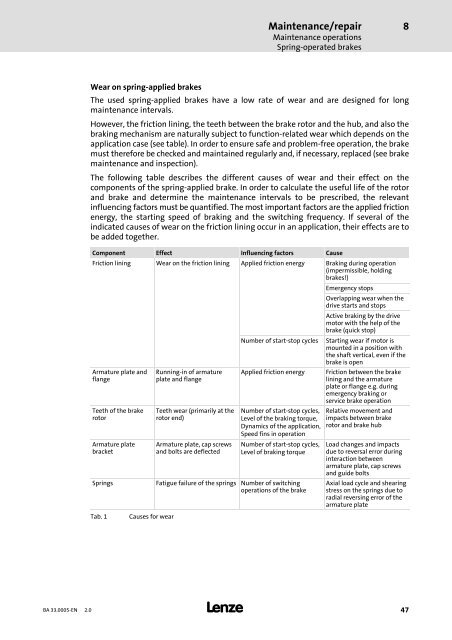
The following table describes the different causes of wear and their effect on the<br />
components of the spring−applied brake. In order to calculate the useful life of the rotor<br />
and brake and determine the maintenance intervals to be prescribed, the relevant<br />
influencing factors must be quantified. The most important factors are the applied friction<br />
energy, the starting speed of braking and the switching frequency. If several of the<br />
indicated causes of wear on the friction lining occur in an application, their effects are to<br />
be added together.<br />
Component Effect Influencing factors Cause<br />
Friction lining Wear on the friction lining Applied friction energy Braking during operation<br />
(impermissible, holding<br />
brakes!)<br />
Emergency stops<br />
Overlapping wear when the<br />
drive starts and stops<br />
Active braking by the drive<br />
motor with the help of the<br />
brake (quick stop)<br />
Number of start−stop cycles Starting wear if motor is<br />
mounted in a position with<br />
the shaft vertical, even if the<br />
brake is open<br />
Armature plate and<br />
flange<br />
Running−in of armature<br />
plate and flange<br />
Applied friction energy Friction between the brake<br />
lining and the armature<br />
plate or flange e.g. during<br />
emergency braking or<br />
service brake operation<br />
Teeth of the brake<br />
rotor<br />
Armature plate<br />
bracket<br />
Teeth wear (primarily at the<br />
rotor end)<br />
Armature plate, cap screws<br />
and bolts are deflected<br />
Number of start−stop cycles,<br />
Level of the braking torque,<br />
Dynamics of the application,<br />
Speed fins in operation<br />
Number of start−stop cycles,<br />
Level of braking torque<br />
Springs Fatigue failure of the springs Number of switching<br />
operations of the brake<br />
Tab. 1<br />
Causes for wear<br />
Relative movement and<br />
impacts between brake<br />
rotor and brake hub<br />
Load changes and impacts<br />
due to reversal error during<br />
interaction between<br />
armature plate, cap screws<br />
and guide bolts<br />
Axial load cycle and shearing<br />
stress on the springs due to<br />
radial reversing error of the<br />
armature plate<br />
BA 33.0005−EN 2.0<br />
47