Steam Generator Installation Manual - Clayton Industries
Steam Generator Installation Manual - Clayton Industries
Steam Generator Installation Manual - Clayton Industries
Create successful ePaper yourself
Turn your PDF publications into a flip-book with our unique Google optimized e-Paper software.
<strong>Steam</strong> <strong>Generator</strong> & Fluid Heater<br />
<strong>Installation</strong> <strong>Manual</strong><br />
Connecting two or more reciprocating PD pumps to a common suction header IS NOT recommended.<br />
Designing such a pump system can frequently cause severe pump pounding, vibration, and premature<br />
check-valve, diaphragm, and electrical component failure. In addition, attempting to analyze the<br />
operation of multiple pumps connected to a common suction header through mathematical calculations is<br />
very difficult.<br />
2.8.2 Velocity Requirements and Calculation<br />
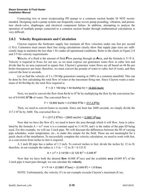
<strong>Clayton</strong> requires the feedwater supply line maintain all flow velocities under one feet per second<br />
(1 ft/s). Customers must ensure their line sizing calculations clearly show that supply pipe sizes are sufficiently<br />
large to maintain the less than 1 ft/s under all operational conditions. Refer to the charts in Figure 2-8<br />
and 2-9 for velocity requirements.<br />
Velocity of a fluid is the amount of fluid Flow passing through an Area, and the formula is V=F/A.<br />
Velocity is required in ft/sec for our use, so we must express our generators water flow in cubic feet and<br />
divide that by an area expressed in square feet. <strong>Clayton</strong>’s generator water flows are all based on 44 lbs per<br />
boiler horsepower per hour; therefore, we must convert the pounds of water to cubic feet of water, and then<br />
convert the hour to seconds.<br />
Let us find the velocity of 3 x 150 bhp generators running at 100% in a common manifold. This can<br />
be done by first calculating the total flow of water at the maximum firing rate. Since <strong>Clayton</strong> wants a minimum<br />
of 44 lbs/bhp-hr, the total flow required is:<br />
F = (3 × 150 bhp × 44 lbs/bhp-hr) = 19,800 lbs/hr<br />
Next, we need to convert the flow from lbs/hr to ft 3 /hr by multiplying the flow by the conversion factor<br />
of 0.01602 ft 3 /lb of water. The converted flow is:<br />
F = 19,800 lbs/hr × 0.01602 ft 3 /lb = 317.2 ft 3 /hr<br />
Then, we need to convert hours to seconds. Since one hour has 3600 seconds, we simply divide the<br />
317.2 ft 3 /hr by 3600. The converted flow is:<br />
F = (317.2 ft 3 /hr) ÷ (3600 sec/hr) = 0.0881 ft 3 /sec<br />
Now that we have the flow (F), we need to know the area through which it will flow. Area is calculated<br />
by the formula A = r 2 were is a constant equal to 3.14159, and r is the radius of the pipe ID being<br />
used. For this example, we will use 3-inch pipe. We will discount the differences between the ID of varying<br />
pipe schedules, water temperature, etc., to make this simple for the field. These are not meaningful for a<br />
quick check of the installation. To successfully complete the velocity calculation, we need to work with feet,<br />
so a conversion from inches to feet is required.<br />
A 3 inch ID pipe has a radius of 1.5 inch. To convert inches to feet, divide the inches by 12 in./ft;<br />
therefore, in our example the radius is 1.5 in. ÷ 12 in./ft = 0.125 ft<br />
A = r 2 = 3.14159 × (0.125 ft) 2 = 0.049 ft 2<br />
Now that we have both the desired flow (0.088 ft 3 /sec) and the available area (0.049 ft 2 ) of the<br />
3-inch pipe it must pass through, we can calculate the velocity.<br />
V = F÷A = (0.0881 ft 3 /sec) ÷ (0.049 ft 2 ) = 1.8 ft/sec<br />
NOTE: Unfortunately, the velocity (V) in our example exceeds <strong>Clayton</strong>’s maximum ft/sec.<br />
Sect02_Genrl-xx4_s.fm 2-18 04/21/2015


