Steam Generator Installation Manual - Clayton Industries
Steam Generator Installation Manual - Clayton Industries
Steam Generator Installation Manual - Clayton Industries

Create successful ePaper yourself
Turn your PDF publications into a flip-book with our unique Google optimized e-Paper software.
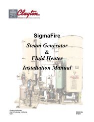
<strong>Steam</strong> <strong>Generator</strong> & Fluid Heater<br />
<strong>Installation</strong> <strong>Manual</strong><br />
The required piping changes are as follows:<br />
• Connect a flexible hose section directly to the reciprocating PD pump’s discharge outlet. (See<br />
paragraph 2.9.2 for flexible hose section requirements.)<br />
• Keep discharge lines as short and direct as possible, well supported, and firmly anchored. This will<br />
ensure minimal pipe vibration, whether hydraulic or mechanical, that can be detrimental to the<br />
pump and generator. Avoid “dead ends” and abrupt direction changes as much as possible.<br />
• Always incorporate 45° angles in the discharge pipe runs by using lateral tees and 45° elbows. DO<br />
NOT connect the pump’s discharge piping directly to a 90° tee/elbow pipe, or other acute-angled<br />
piping. These types of connections will create “standing wave” or “bounce-back,” either audible or<br />
sub-audible, that causes excessive vibration and noise.<br />
• Use laterals in place of tees with the bottom of the Y facing the direction of pumped water flow.<br />
Use long radius elbows, or two 45° elbows, throughout the discharge piping system from the flexible<br />
hose discharge connection to the heating coil inlet connection.<br />
• Increase the pipe sizes by at least one full size over the reciprocating PD feedwater pump’s discharge<br />
connection (i.e.: a 1 1/2 or 2 inch discharge requires an increase to 3 inches minimum).<br />
• Use of butt-weld pipe with weld-neck flange construction throughout the discharge pipe run is recommended.<br />
• Discharge flow velocities must be maintained below 5 ft/sec. maximum.<br />
• DO NOT install angle valves, globe valves, reduced port regular opening valves, restricting plug<br />
valves, flow restriction orifices, or small ventures in the discharge pipe run.<br />
• DO NOT install any quick-closing valves, which can cause hydraulic shock (water hammering) in<br />
the discharge piping run.<br />
• Connect the pressure relief valve and pressure gauge with snubber ahead of any block valve so that<br />
the pump discharge pressure is always reflected at the relief valve. The relieving capacity of the<br />
valve must exceed the full capacity of the pump to avoid excessive pressure while relieving flow.<br />
Use only full-sized relief line design with no restrictions.<br />
• Should the <strong>Clayton</strong> reciprocating PD pump’s pressure relief valve be removed, it must be replaced<br />
with a properly sized and correctly set pressure relief valve. Relief valve discharge must not be<br />
piped to reciprocating PD pump’s suction line.<br />
• Install a 2-inch NPTF weld couplet vertically upward, as close as possible, to the reciprocating PD<br />
pump’s discharge connector to allow the addition of nitrogen-filled pulsation dampeners.<br />
• All discharge pipe and pipe fittings must be at minimum Schedule 80.<br />
2.11 Net Positive Suction Head (NPSH)<br />
NPSH relates to the fluid pressure (generally in terms of “head” of water, or psi) that a pump needs to<br />
prevent flashing or cavitation within the pump, primarily in the suction check-valve area. Flashing and cavitation<br />
will reduce necessary flow rates and cause damage to the internal pump components and coil.<br />
NPSH is divided into two important aspects, (A) what is available (NPSH A ) from the suction vessel,<br />
booster pump(s), and piping, and (B) what is required by the pump (NPSH R ).<br />
Sect02_Genrl-xx4_s.fm 2-24 04/21/2015