Steam Generator Installation Manual - Clayton Industries
Steam Generator Installation Manual - Clayton Industries
Steam Generator Installation Manual - Clayton Industries

Create successful ePaper yourself
Turn your PDF publications into a flip-book with our unique Google optimized e-Paper software.
STEAM GENERATOR & FLUID HEATER<br />
INSTALLATION MANUAL<br />
ical treatment to react. Condensate, separator trap returns and feedwater treatment chemicals are<br />
injected at the opposite end of the tank as the feedwater outlet connection. This helps to avoid<br />
potential feedwater delivery problems to the Booster or Feedwater Pump(s), and to provide sufficient<br />
reaction time for the chemical treatment.<br />
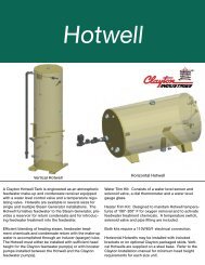
If not skid mounted, the Feedwater Receiver should be installed horizontally, as shown in<br />
Drawing R-16099. If the Feedwater Receiver cannot be elevated to provide the required NPSH,<br />
Booster Pumps must be used. The Feedwater Receiver can be insulated to maximize heat retention.<br />
<strong>Installation</strong> guidelines for the Feedwater Receiver are provided below. Descriptions for<br />
the other water treatment and accessory components, shown in R-16099, are provided in Section<br />
VII (Optional Equipment) and/or in the <strong>Clayton</strong> Feedwater Treatment <strong>Manual</strong>.<br />
NOTE<br />
All piping to and from the feedwater receiver must remain the same or<br />
larger size as the tank connection and not reduced. See Table 3-3 below for<br />
connection requirements.<br />
Table 3-3: Feedwater Receiver Connections<br />
Feedwater<br />
Outlet<br />
Gravity Fill<br />
Vent<br />
Chemical<br />
Injection<br />
Overflow<br />
This is the supply connection for properly-treated feedwater to the booster pump(s) or<br />
feedwater pump(s). Depending on the tank size, this connection may be either on the<br />
bottom or on the side of the tank. A valve and strainer (0.125 mesh) must be installed in<br />
the feedwater supply piping at the inlet to each pump (shipped loose if <strong>Clayton</strong><br />
furnished - except on Skids). Feedwater line must be constructed to provide<br />
the required NPSH, velocity under 1 ft/s, and acceleration head losses<br />
less than those shown in Section 2.11 to the feedwater pump inlet.<br />
Restrictions in this line will cause water delivery problems that may result in pump<br />
cavitation and water shortage problems in the heating coil.<br />
Install a pipe tee in the feedwater outlet line just below the feedwater outlet connection.<br />
On an elevated receiver system, this pipe tee provides a connection for the gravity fill<br />
plumbing coming from the heating coil.<br />
Vent piping must be installed so as not create back pressure on the hotwell. The vent<br />
pipe should be as short as possible, contain no valves or restrictions, and run straight up<br />
and out. Ninety degree elbows are to be avoided. A 45 o offset should be provided at the<br />
end of the vent line to prevent system contamination during severe weather conditions<br />
and/or during shutdown periods.<br />
One common feedwater chemical injection connection is provided into which all<br />
feedwater treatment chemicals are introduced. A check-valve must be installed in the<br />
discharge line of each chemical pumping system.<br />
No valves are to be installed in the overflow piping. Overflow piping must be plumbed<br />
to the blowdown tank discharge piping at a point prior to the temperature valve sensor.<br />
The overflow line must be full size, not reduced. <strong>Clayton</strong> recommends installing a “Ptrap”<br />
on all overflow lines.<br />
Sect03_FeedwtrSys_xx4_f.fm 3-4 04/22/2015