
Create successful ePaper yourself
Turn your PDF publications into a flip-book with our unique Google optimized e-Paper software.
GUZUNTY PI<br />
GCLK3, GND.<br />
Power<br />
I used 3 wires for the IO-Expansion:<br />
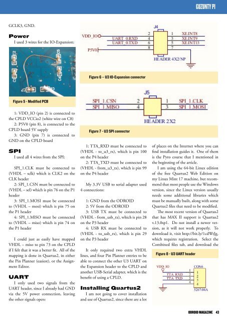
Figure 6 – U3 IO-Expansion connector<br />
Figure 5 - Modified PCB<br />
1: VDD_IO (pin 2) is connected to<br />
the CPLD VCCio2 (white wire on C8)<br />
2: P5V0 (pin 8), is connected to the<br />
CPLD board 5V supply<br />
3: GND (pin 7) is connected to<br />
GND on the CPLD board<br />
SPI<br />
I used all 4 wires from the SPI:<br />
SPI_1.CLK must be connected to<br />
(VHDL – sclk) which is CLK2 on the<br />
CLK header<br />
2: SPI_1.CSN must be connected to<br />
(VHDL – sel) which is pin 76 on the P1<br />
header<br />
3: SPI_1.MOSI must be connected<br />
to (VHDL – mosi) which is pin 75 on<br />
the P1 header<br />
4: SPI_1.MISO must be connected<br />
to (VHDL – miso) which is pin 74 on<br />
the P1 header<br />
I could just as easily have mapped<br />
VHDL – miso to pin 73 on the CPLD<br />
if I felt that it was a better fit. All of the<br />
mapping is done in Quartus2, in either<br />
the Pin Planner (easiest), or the Assignment<br />
Editor.<br />
UART<br />
I only used two signals from the<br />
UART header, since I already had GND<br />
via the 5V power connection, leaving<br />
the other signals open:<br />
Figure 7 - U3 SPI connector<br />
1: TTA_RXD must be connected to<br />
(VHDL - to_u3_rx), which is pin 100<br />
on the P4 header<br />
2: TTA_TXD must be connected to<br />
(VHDL - from_u3_tx), which is pin 99<br />
on the P4 header<br />
My 3.3V USB to serial adapter used<br />
4 connections:<br />
1: GND from the <strong>ODROID</strong><br />
2: 5V from the <strong>ODROID</strong><br />
3: USB TX must be connected to<br />
(VHDL - from_usb_tx), which is pin 28<br />
on the P3 header<br />
4: USB RX must be connected to<br />
(VHDL - to_usb_rx), which is pin 29<br />
on the P3 header<br />
It only required two extra VHDL<br />
lines, and four Pin Planner entries to be<br />
able to connect the other U3 UART on<br />
the Expansion header to the CPLD and<br />
another USB-Serial adapter, which is the<br />
benefit of using a CPLD.<br />
Installing Quartus2<br />
I am not going to cover installation<br />
and use of Quartus2, since there are a lot<br />
of places on the Internet where you can<br />
find installation guides it. One of them<br />
is the Pyro course that I mentioned in<br />
the beginning of the article.<br />
I am using the 64-bit Linux edition<br />
of the free Quartus2 Web Edition on<br />
my Linux Mint 17 machine, but recommend<br />
that most people use the Windows<br />
version, since the Linux version usually<br />
needs some additional libraries which<br />
must be manually built, along with some<br />
Quartus2 files that need to be modified.<br />
The most recent version of Quartus2<br />
that has MAX II support is Quartus2<br />
v.13.0sp1. Do not install a newer version,<br />
as it will not work properly. To<br />
download it, visit http://bit.ly/1cdWtJg,<br />
which requires registration. Select the<br />
Combined files tab, and download the<br />
Figure 8 - U3 UART header<br />
<strong>ODROID</strong> MAGAZINE 43