crossmax slr disc 09 - lesrouleuxdewailly - Free
crossmax slr disc 09 - lesrouleuxdewailly - Free
crossmax slr disc 09 - lesrouleuxdewailly - Free

You also want an ePaper? Increase the reach of your titles
YUMPU automatically turns print PDFs into web optimized ePapers that Google loves.
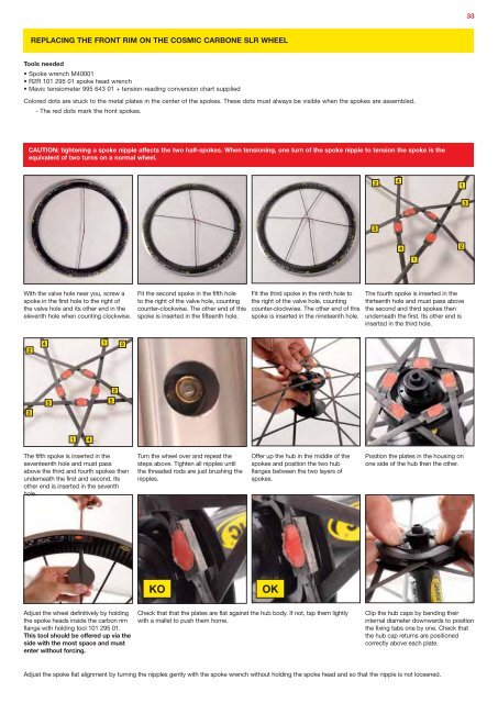
33<br />
REPLACING THE FRONT RIM ON THE COSMIC CARBONE SLR WHEEL<br />
Tools needed<br />
• Spoke wrench M40001<br />
• R2R 101 295 01 spoke head wrench<br />
• Mavic tensiometer 995 643 01 + tension-reading conversion chart supplied<br />
Colored dots are stuck to the metal plates in the center of the spokes. These dots must always be visible when the spokes are assembled.<br />
- The red dots mark the front spokes.<br />
CAUTION: tightening a spoke nipple affects the two half-spokes. When tensioning, one turn of the spoke nipple to tension the spoke is the<br />
equivalent of two turns on a normal wheel.<br />
2<br />
4<br />
1<br />
3<br />
3<br />
4<br />
2<br />
1<br />
With the valve hole near you, screw a<br />
spoke in the first hole to the right of<br />
the valve hole and its other end in the<br />
eleventh hole when counting clockwise.<br />
Fit the second spoke in the fifth hole<br />
to the right of the valve hole, counting<br />
counter-clockwise. The other end of this<br />
spoke is inserted in the fifteenth hole.<br />
Fit the third spoke in the ninth hole to<br />
the right of the valve hole, counting<br />
counter-clockwise. The other end of this<br />
spoke is inserted in the nineteenth hole.<br />
The fourth spoke is inserted in the<br />
thirteenth hole and must pass above<br />
the second and third spokes then<br />
underneath the first. Its other end is<br />
inserted in the third hole.<br />
2<br />
4<br />
1<br />
3<br />
3<br />
5<br />
5<br />
2<br />
1<br />
4<br />
The fifth spoke is inserted in the<br />
seventeenth hole and must pass<br />
above the third and fourth spokes then<br />
underneath the first and second. Its<br />
other end is inserted in the seventh<br />
hole.<br />
Turn the wheel over and repeat the<br />
steps above. Tighten all nipples until<br />
the threaded rods are just brushing the<br />
nipples.<br />
Offer up the hub in the middle of the<br />
spokes and position the two hub<br />
flanges between the two layers of<br />
spokes.<br />
Position the plates in the housing on<br />
one side of the hub then the other.<br />
KO<br />
OK<br />
Adjust the wheel definitively by holding<br />
the spoke heads inside the carbon rim<br />
flange with holding tool 101 295 01.<br />
This tool should be offered up via the<br />
side with the most space and must<br />
enter without forcing.<br />
Check that that the plates are flat against the hub body. If not, tap them lightly<br />
with a mallet to push them home.<br />
Clip the hub caps by bending their<br />
internal diameter downwards to position<br />
the fixing tabs one by one. Check that<br />
the hub cap returns are positioned<br />
correctly above each plate.<br />
Adjust the spoke flat alignment by turning the nipples gently with the spoke wrench without holding the spoke head and so that the nipple is not loosened.