crossmax slr disc 09 - lesrouleuxdewailly - Free
crossmax slr disc 09 - lesrouleuxdewailly - Free
crossmax slr disc 09 - lesrouleuxdewailly - Free

Create successful ePaper yourself
Turn your PDF publications into a flip-book with our unique Google optimized e-Paper software.
39<br />
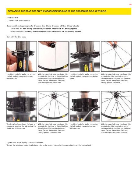
REPLACING THE REAR RIM ON THE CROSSRIDE UB/DISC <strong>09</strong> AND CROSSRIDE DISC <strong>09</strong> WHEELS<br />
Tools needed<br />
• Conventional spoke wrench<br />
Basic wheel building principles for Crossride Disc <strong>09</strong> and Crossride UB/Disc <strong>09</strong> rear wheels:<br />
- Drive side: the non-driving spokes are positioned underneath the driving spokes.<br />
- Non-drive side: the driving spokes are positioned underneath the non-driving spokes.<br />
Start with the drive side;<br />
Insert the head of a spoke in a slot on<br />
the hub so that the spoke is a nondriving<br />
spoke.<br />
With the valve hole near you, insert this<br />
spoke in the first hole to the right of the<br />
valve hole and tighten its nipple two<br />
turns. Repeat these steps for the six<br />
non-driving spokes, drive side.<br />
Insert the head of a spoke in a slot on<br />
the hub so that the spoke is a driving<br />
spoke.<br />
With the valve hole near you, insert this<br />
spoke in the third hole to the right of<br />
the valve hole and tighten its nipple two<br />
turns. Repeat these steps for the six<br />
driving spokes, drive side.<br />
Turn the wheel over. Insert the head of<br />
a spoke in a slot on the hub so that the<br />
spoke is a driving spoke.<br />
With the valve hole near you, insert this<br />
spoke in the first hole to the right of the<br />
valve hole and tighten its nipple two<br />
turns. Repeat these steps for the six<br />
driving spokes, non-drive side.<br />
Insert the head of a spoke in a slot on<br />
the hub so that the spoke is a nondriving<br />
spoke.<br />
With the valve hole near you, insert this<br />
spoke in the third hole to the right of<br />
the valve hole and tighten its nipple two<br />
turns. Repeat these steps for the six<br />
non-driving spokes, non-drive side.<br />
Tighten each nipple equally to tension the wheel.<br />
Tension the wheel and center it definitively (refer to the product pages for the appropriate tension for each wheel).