crossmax slr disc 09 - lesrouleuxdewailly - Free
crossmax slr disc 09 - lesrouleuxdewailly - Free
crossmax slr disc 09 - lesrouleuxdewailly - Free

You also want an ePaper? Increase the reach of your titles
YUMPU automatically turns print PDFs into web optimized ePapers that Google loves.
44<br />
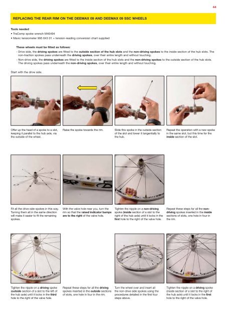
REPLACING THE REAR RIM ON THE DEEMAX <strong>09</strong> AND DEEMAX <strong>09</strong> SSC WHEELS<br />
Tools needed<br />
• TraComp spoke wrench M40494<br />
• Mavic tensiometer 995 643 01 + tension-reading conversion chart supplied<br />
These wheels must be fitted as follows:<br />
- Drive side, the driving spokes are fitted to the outside section of the hub slots and the non-driving spokes to the inside section of the hub slots. The<br />
non-traction spokes pass underneath the driving spokes, over their entire length and without touching.<br />
- Non-drive side, the driving spokes are fitted to the inside section of the hub slots and the non-driving spokes to the outside section of the hub slots.<br />
The driving spokes pass underneath the non-driving spokes, over their entire length and without touching.<br />
Start with the drive side.<br />
Offer up the head of a spoke to a slot,<br />
keeping it parallel to the hub axle, via<br />
the outside of the wheel.<br />
Raise the spoke towards the rim.<br />
Slide this spoke in the outside section<br />
of the slot and lower it tangentially to<br />
the hub.<br />
Repeat the operation with a new spoke<br />
in the same slot, but this time for the<br />
inside section of the slot.<br />
Fit all the drive side spokes in this way.<br />
Turning them all in the same direction<br />
will make it easier to fit the remaining<br />
spokes.<br />
With the valve hole near you, turn the<br />
rim so that the raised indicator bumps<br />
are to the right of the valve hole.<br />
Tighten the nipple on a non-driving<br />
spoke (inside section of a slot to the<br />
right of the hub axle) until it locks in the<br />
first hole to the right of the valve hole.<br />
Repeat these steps for all the nondriving<br />
spokes inserted in the inside<br />
sections of slots, one hole in four in<br />
the rim.<br />
Tighten the nipple on a driving spoke<br />
(outside section of a slot to the left of<br />
the hub axle) until it locks in the third<br />
hole to the right of the valve hole.<br />
Repeat these steps for all the driving<br />
spokes inserted in the outside sections<br />
of slots, one hole in four in the rim.<br />
Turn the wheel over and insert all<br />
the non-drive side spokes using the<br />
procedures detailed in the first four<br />
steps above.<br />
Tighten the nipple on a driving spoke<br />
(inside section of a slot to the right of<br />
the hub axle) until it locks in the first<br />
hole to the right of the valve hole.