crossmax slr disc 09 - lesrouleuxdewailly - Free
crossmax slr disc 09 - lesrouleuxdewailly - Free
crossmax slr disc 09 - lesrouleuxdewailly - Free

Create successful ePaper yourself
Turn your PDF publications into a flip-book with our unique Google optimized e-Paper software.
34<br />
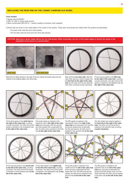
REPLACING THE REAR RIM ON THE COSMIC CARBONE SLR WHEEL<br />
Tools needed<br />
• Spoke wrench M40001<br />
• R2R 101 295 01 spoke head wrench<br />
• Mavic tensiometer 995 643 01 + tension-reading conversion chart supplied<br />
Colored dots are stuck to the metal plates in the center of the spokes. These dots must always be visible when the spokes are assembled.<br />
- The green dots mark the drive-side spokes.<br />
- The red dots mark the front and non-drive side spokes.<br />
CAUTION: tightening a spoke nipple affects the two half-spokes. When tensioning, one turn of the spoke nipple to tension the spoke is the<br />
equivalent of two turns on a normal wheel.<br />
DRIVE SIDE<br />
NON DRIVE SIDE<br />
Mark the rim fitting direction: the side of the rim where the spoke holes are the<br />
nearest to the leaking edge is the drive side.<br />
Start with the non-drive side. With the<br />
valve hole near you, screw a spoke into<br />
the first hole to the right of the valve<br />
hole and its other end into the eleventh<br />
hole when counting counter-clockwise.<br />
Fit the second spoke in the fifth hole<br />
to the right of the valve hole, counting<br />
counter-clockwise. The other end of this<br />
spoke is inserted in the fifteenth hole, to<br />
the right of the valve hole.<br />
2<br />
4<br />
1<br />
3<br />
2<br />
4<br />
1<br />
3<br />
3<br />
2<br />
5<br />
3<br />
5<br />
2<br />
1<br />
4<br />
1<br />
4<br />
Fit the third spoke in the ninth hole to<br />
the right of the valve hole, counting<br />
counter-clockwise. The other end of this<br />
spoke is inserted in the nineteenth hole,<br />
to the right of the valve hole.<br />
The fourth spoke is inserted in the<br />
thirteenth hole to the right of the valve<br />
hole and must pass over the second<br />
and third spokes then underneath the<br />
first. Its other end is inserted in the third<br />
hole to the right of the valve hole.<br />
The fifth spoke is inserted in the<br />
seventeenth hole to the right of the<br />
valve hole and must pass over the third<br />
and fourth spokes then underneath<br />
the first and second. Its other end is<br />
inserted in the seventh hole to the right<br />
of the valve hole.<br />
3 3<br />
5<br />
Turn the wheel over. Insert a spoke in<br />
the first hole to the right of the valve<br />
hole. The other end of this spoke is<br />
inserted in the eleventh hole, counting<br />
counter-clockwise.<br />
1<br />
4<br />
1<br />
4<br />
4<br />
2<br />
4<br />
2<br />
2<br />
3 3<br />
1 1<br />
2<br />
5<br />
Fit the second spoke in the fourth hole<br />
to the left of the valve hole, counting<br />
clockwise. The other end of this spoke<br />
is inserted in the fourteenth hole, to the<br />
left of the valve hole.<br />
Fit the third spoke in the eighth hole<br />
to the left of the valve hole, counting<br />
clockwise. The other end of this spoke<br />
is inserted in the eighteenth hole, to the<br />
left of the valve hole.<br />
The fourth spoke is inserted in the<br />
twelfth hole to the left of the valve hole<br />
and must pass underneath the first<br />
spoke then over the third and second<br />
spokes. Its other end is inserted in the<br />
second hole to the left of the valve<br />
hole.<br />
The fifth spoke is inserted in the<br />
sixteenth hole to the left of the valve<br />
hole and must pass underneath the<br />
second and first spokes, then over the<br />
fourth and third. Its other end is inserted<br />
in the sixth hole to the left of the valve<br />
hole.