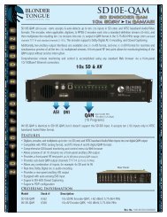
Functional Block Diagram - Blonder Tongue Laboratories Inc.
Functional Block Diagram - Blonder Tongue Laboratories Inc.
Functional Block Diagram - Blonder Tongue Laboratories Inc.

Create successful ePaper yourself
Turn your PDF publications into a flip-book with our unique Google optimized e-Paper software.
Broadband Specification Guide<br />
Cherry Picking From a Cable TV Feed<br />
<strong>Functional</strong>ity<br />
This system will allow you to select a few desired channels from the local cable TV company and ignore all of<br />
the other undesired channels. This signal can now be handed off to a traditional coaxial distribution network<br />
or a hybrid fiber / coaxial distribution network within the facility.<br />
In Depth Description<br />
There are two different sets of electronics that can be employed to create the desired channel line up. The<br />
first method is to employ a channel processor. Channel processors come in several different versions, but all<br />
do basically the same thing, they take one channel on the input, and convert it into another on the output. If<br />
the channel line up is known well in advance, fixed processors can be used to minimize cost. The downside of<br />
fixed processors is that if the local cable TV company changes it’s channel line up, another processor would<br />
need to be purchased.<br />
Agile processors are able to change both the input, and the output channel on the fly to be able to<br />
accommodate any changes that might be necessary. The keys to success in this system are making sure that<br />
the processors have enough input signal to function correctly and making sure that the output levels are all set<br />
correctly so the channels do not interfere with each other.<br />
The second method is to employ a demodulator and modulator in series. The demodulator is an agile device<br />
that can be set up to receive a TV channel input signal. Its function is to extract the audio and video information<br />
from the RF carriers and provide separate audio and video output signals. These separate audio and video<br />
feeds, also called baseband audio and video, are then applied to a modulator. It is the job of the modulator to<br />
take the audio and video and make them in to a cable TV channel. This channel can then be combined with<br />
other channels that have been created at the property. The keys to success in this system are making sure<br />
that the demodulators have enough input signal to function correctly and making sure that the modulator is<br />
adjusted correctly for proper modulation and output levels.<br />
If you pick one product from each category on the following pages, you will have all of the components to<br />
ensure a working design. Once all of the products are identified, the specifications can be looked up in the<br />
specification library at the end of this publication.<br />
30