DESIGN SPECIFICATIONS FOR HIGHWAY BRIDGES - IISEE
DESIGN SPECIFICATIONS FOR HIGHWAY BRIDGES - IISEE
DESIGN SPECIFICATIONS FOR HIGHWAY BRIDGES - IISEE

You also want an ePaper? Increase the reach of your titles
YUMPU automatically turns print PDFs into web optimized ePapers that Google loves.
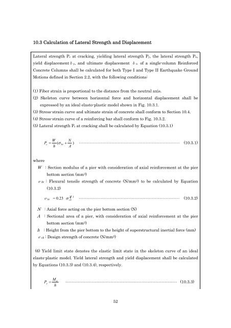
10.3 Calculation of Lateral Strength and Displacement<br />
Lateral strength Pc at cracking, yielding lateral strength Py, the lateral strength Pu,<br />
yield displacementδy, and ultimate displacement δu of a single-column Reinforced<br />
Concrete Columns shall be calculated for both Type I and Type II Earthquake Ground<br />
Motions defined in Section 2.2, with the following conditions:<br />
(1) Fiber strain is proportional to the distance from the neutral axis.<br />
(2) Skeleton curve between horizontal force and horizontal displacement shall be<br />
expressed by an ideal elasto-plastic model shown in Fig. 10.3.1.<br />
(3) Stress-strain curve and ultimate strain of concrete shall conform to Section 10.4.<br />
(4) Stress-strain curve of a reinforcing bar shall conform to Fig. 10.3.2.<br />
(5) Lateral strength Pc at cracking shall be calculated by Equation (10.3.1)<br />
P<br />
c<br />
W N<br />
( bt<br />
) ・・・・・・・・・・・・・・・・・・・・・・・・・・・・・・・・・・・・・・・・・・・・・・・・・・・・・・・・・・・・・・・・・ (10.3.1)<br />
h A<br />
where<br />
W : Section modulus of a pier with consideration of axial reinforcement at the pier<br />
bottom section (mm 3 )<br />
σbt : Flexural tensile strength of concrete (N/mm 2 ) to be calculated by Equation<br />
(10.3.2)<br />
σ bt = 0.23<br />
2 3<br />
<br />
ck ・・・・・・・・・・・・・・・・・・・・・・・・・・・・・・・・・・・・・・・・・・・・・・・・・・・・・・・・・・・・・・・・・ (10.3.2)<br />
N : Axial force acting on the pier bottom section (N)<br />
A : Sectional area of a pier, with consideration of axial reinforcement at the pier<br />
bottom section (mm 2 )<br />
h : Height from the pier bottom to the height of superstructural inertial force (mm)<br />
σck : Design strength of concrete (N/mm 2 )<br />
(6) Yield limit state denotes the elastic limit state in the skeleton curve of an ideal<br />
elasto-plastic model. Yield lateral strength and yield displacement shall be calculated<br />
by Equations (10.3.3) and (10.3.4), respectively.<br />
M<br />
u<br />
Py ・・・・・・・・・・・・・・・・・・・・・・・・・・・・・・・・・・・・・・・・・・・・・・・・・・・・・・・・・・・・・・・・・・・・・・・・ (10.3.3)<br />
h<br />
52