DESIGN SPECIFICATIONS FOR HIGHWAY BRIDGES - IISEE
DESIGN SPECIFICATIONS FOR HIGHWAY BRIDGES - IISEE
DESIGN SPECIFICATIONS FOR HIGHWAY BRIDGES - IISEE

Create successful ePaper yourself
Turn your PDF publications into a flip-book with our unique Google optimized e-Paper software.
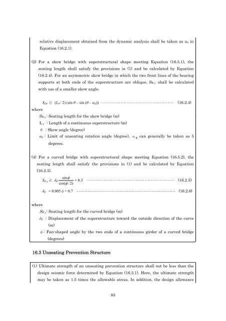
elative displacement obtained from the dynamic analysis shall be taken as uR in<br />
Equation (16.2.1).<br />
(2) For a skew bridge with superstructural shape meeting Equation (16.5.1), the<br />
seating length shall satisfy the provisions in (1) and be calculated by Equation<br />
(16.2.4). For an asymmetric skew bridge in which the two front lines of the bearing<br />
supports at both ends of the superstructure are oblique, SE θ shall be calculated<br />
with use of a smaller skew angle.<br />
S Eθ ≧ (L θ / 2) (sin θ – sin (θ – α E )) ・・・・・・・・・・・・・・・・・・・・・・・・・・・・・・・・・・・・・・・・・・・・・・・・ (16.2.4)<br />
where<br />
SE θ : Seating length for the skew bridge (m)<br />
L θ : Length of a continuous superstructure (m)<br />
θ : Skew angle (degree)<br />
α E : Limit of unseating rotation angle (degree), α E<br />
can generally be taken as 5<br />
degrees.<br />
(4) For a curved bridge with superstructural shape meeting Equation (16.5.2), the<br />
seating length shall satisfy the provisions in (1) and be calculated by Equation<br />
(16.2.5).<br />
sin<br />
S Eφ ≧ δ E + 0.3 ・・・・・・・・・・・・・・・・・・・・・・・・・・・・・・・・・・・・・・・・・・・・・・・・・・・・・・・・・・ (16.2.5)<br />
cos( / 2)<br />
δ E = 0.005φ+ 0.7 ・・・・・・・・・・・・・・・・・・・・・・・・・・・・・・・・・・・・・・・・・・・・・・・・・・・・・・・・・・・・・・・・・ (16.2.6)<br />
where<br />
SE φ : Seating length for the curved bridge (m)<br />
δ E : Displacement of the superstructure toward the outside direction of the curve<br />
(m)<br />
φ: Fan-shaped angle by the two ends of a continuous girder of a curved bridge<br />
(degrees)<br />
16.3 Unseating Prevention Structure<br />
(1) Ultimate strength of an unseating prevention structure shall not be less than the<br />
design seismic force determined by Equation (16.3.1). Here, the ultimate strength<br />
may be taken as 1.5 times the allowable stress. In addition, the design allowance<br />
85