DESIGN SPECIFICATIONS FOR HIGHWAY BRIDGES - IISEE
DESIGN SPECIFICATIONS FOR HIGHWAY BRIDGES - IISEE
DESIGN SPECIFICATIONS FOR HIGHWAY BRIDGES - IISEE

You also want an ePaper? Increase the reach of your titles
YUMPU automatically turns print PDFs into web optimized ePapers that Google loves.
Girder<br />
Girder<br />
Girder<br />
Pier<br />
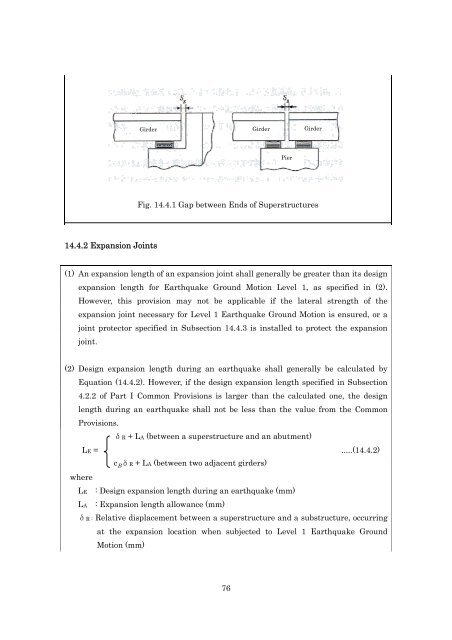
Fig. 14.4.1 Gap between Ends of Superstructures<br />
14.4.2 Expansion Joints<br />
(1) An expansion length of an expansion joint shall generally be greater than its design<br />
expansion length for Earthquake Ground Motion Level 1, as specified in (2).<br />
However, this provision may not be applicable if the lateral strength of the<br />
expansion joint necessary for Level 1 Earthquake Ground Motion is ensured, or a<br />
joint protector specified in Subsection 14.4.3 is installed to protect the expansion<br />
joint.<br />
(2) Design expansion length during an earthquake shall generally be calculated by<br />
Equation (14.4.2). However, if the design expansion length specified in Subsection<br />
4.2.2 of Part I Common Provisions is larger than the calculated one, the design<br />
length during an earthquake shall not be less than the value from the Common<br />
Provisions.<br />
δR + LA (between a superstructure and an abutment)<br />
LE = .....(14.4.2)<br />
c B δR + LA (between two adjacent girders)<br />
where<br />
LE : Design expansion length during an earthquake (mm)<br />
LA : Expansion length allowance (mm)<br />
δR : Relative displacement between a superstructure and a substructure, occurring<br />
at the expansion location when subjected to Level 1 Earthquake Ground<br />
Motion (mm)<br />
76