To the Graduate Council: I am submitting herewith a thesis written by ...
To the Graduate Council: I am submitting herewith a thesis written by ...
To the Graduate Council: I am submitting herewith a thesis written by ...

Create successful ePaper yourself
Turn your PDF publications into a flip-book with our unique Google optimized e-Paper software.
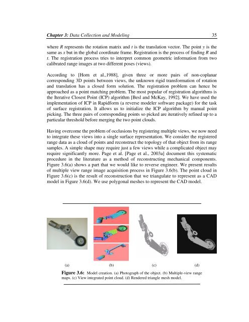
Chapter 3: Data Collection and Modeling 35where R represents <strong>the</strong> rotation matrix and t is <strong>the</strong> translation vector. The point y is <strong>the</strong>s<strong>am</strong>e as x but in <strong>the</strong> global coordinate fr<strong>am</strong>e. Registration is <strong>the</strong> process of finding R andt. The registration process tries to interpret common geometric information from twocalibrated range images at two different poses (views).According to [Horn et al.,1988], given three or more pairs of non-coplanarcorresponding 3D points between views, <strong>the</strong> unknown rigid transformation of rotationand translation has a closed form solution. The registration problem can hence beapproached as a point matching problem. The most popular of registration algorithms is<strong>the</strong> Iterative Closest Point (ICP) algorithm [Besl and McKay, 1992]. We have used <strong>the</strong>implementation of ICP in Rapidform (a reverse modeler software package) for <strong>the</strong> taskof surface registration. It allows us to initialize <strong>the</strong> ICP algorithm <strong>by</strong> manual pointpicking. The three pairs of corresponding points so picked are iteratively refined up to aparticular threshold before merging <strong>the</strong> two point clouds.Having overcome <strong>the</strong> problem of occlusions <strong>by</strong> registering multiple views, we now needto integrate <strong>the</strong>se views into a single surface representation. We consider <strong>the</strong> registeredrange data as a cloud of points and reconstruct <strong>the</strong> topology of that object from its ranges<strong>am</strong>ples. A simple shape may require just a few views while a complicated object mayrequire significantly more. Page et al. [Page et al., 2003a] document this systematicprocedure in <strong>the</strong> literature as a method of reconstructing mechanical components.Figure 3.6(a) shows a part that we would like to reverse engineer. We present resultsof multiple view range image acquisition process in Figure 3.6(b). The point cloud inFigure 3.6(c) is <strong>the</strong> result of reconstruction that we triangulate to represent as a CADmodel in Figure 3.6(d). We use polygonal meshes to represent <strong>the</strong> CAD model.(a) (b) (c) (d)Figure 3.6: Model creation. (a) Photograph of <strong>the</strong> object. (b) Multiple-view rangemaps. (c) View integrated point cloud. (d) Rendered triangle mesh model.