vacon 100 installation manual - VEM motors Finland Oy
vacon 100 installation manual - VEM motors Finland Oy
vacon 100 installation manual - VEM motors Finland Oy

Create successful ePaper yourself
Turn your PDF publications into a flip-book with our unique Google optimized e-Paper software.
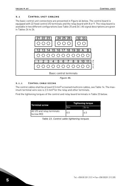
<strong>vacon</strong> • 49Control unit5.1 Control unit cablingThe basic control unit connections are presented in Figure 46 below. The control board isequipped with 22 fixed control I/O terminals and the relay board with 8 or 9. The relay board isavailable in two different configurations (see Table 25 and 26 ). All signal descriptions are givenin Tables 24 to 26.21 22 23 24 25 26 32 3312 13 14 15 16 17 18 19 30 A B1 2 3 4 5 6 7 8 9 10 11Basic control terminalsFigure 46.5.1.1 Control cable sizingThe control cables shall be at least 0.5 mm 2 screened multicore cables, see Table 14. The maximumterminal wire size is 2.5 mm 2 for the relay and other terminals.Find the tightening torques of the control and relay board terminals in Table 23 below.Terminal screwAll I/O and relay terminals(screw M3)Tightening torqueNmlb-in.0.5 4.5Table 23. Control cable tightening torques5Tel. +358 (0) 201 2121 • Fax +358 (0)201 212 205