vacon 100 installation manual - VEM motors Finland Oy
vacon 100 installation manual - VEM motors Finland Oy
vacon 100 installation manual - VEM motors Finland Oy

You also want an ePaper? Increase the reach of your titles
YUMPU automatically turns print PDFs into web optimized ePapers that Google loves.
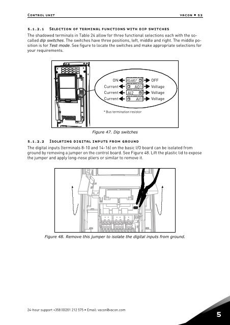
Control unit <strong>vacon</strong> • 525.1.2.1 Selection of terminal functions with dip switchesThe shadowed terminals in Table 24 allow for three functional selections each with the socalleddip switches. The switches have three positions, left, middle and right. The middle positionis for Test mode. See figure to locate the switches and make appropriate selections foryour requirements.ONCurrentCurrentCurrentRS485*AO1AI2AI1OFFVoltageVoltageVoltage* Bus termination resistorFigure 47. Dip switches5.1.2.2 Isolating digital inputs from groundThe digital inputs (terminals 8-10 and 14-16) on the basic I/O board can be isolated fromground by removing a jumper on the control board. See Figure 48. Lift the plastic lid to exposethe jumper and apply long-nose pliers or similar to remove it.Figure 48. Remove this jumper to isolate the digital inputs from ground.24-hour support +358 (0)201 212 575 • Email: <strong>vacon</strong>@<strong>vacon</strong>.com5