
You also want an ePaper? Increase the reach of your titles
YUMPU automatically turns print PDFs into web optimized ePapers that Google loves.
0<br />
DELTABOOSTER_GB01<br />
Structure<br />
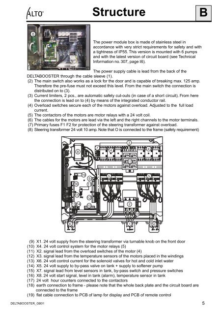
The power module box is made of stainless steel in<br />
accordance with very strict requirements for safety and with<br />
a tightness of IP55. This version is mounted with 6 pumps<br />
and with the latest version of circuit board (see Technical<br />
Information no. 307, page I6).<br />
The power supply cable is lead from the back of the<br />
DELTABOOSTER through the cable sleeve (1).<br />
(2) The main switch also works as a lock for the door and is capable of breaking max. 125 amp.<br />
Therefore the pre-fuse must not exceed this level. From the main switch the connection is<br />
distributed on to (3).<br />
(3) Current limiters, 2 pcs., are automatic safety cut-outs (in case of a short circuit). From here<br />
the connection is lead on to (4) by means of the integrated conductor rail.<br />
(4) Overload switches secure each of the motors against overload. Adjusted to the full load<br />
current.<br />
(5) The contactors of the motors are motor relays with a 24 volt coil.<br />
(6) The cables for the motors are lead via the left and the right channels to the motor terminals.<br />
(7) Primary fuses F1 F2 for protection of the steering transformer against overload.<br />
(8) Steering transformer 24 volt 10 amp. Note that O is connected to the frame (safety requirement)<br />
6<br />
8<br />
16<br />
15<br />
13 14<br />
19<br />
9<br />
11<br />
12<br />
10<br />
7<br />
4<br />
(9) X1. 24 volt supply from the steering transformer via turnable knob on the front door<br />
(10) X4. 24 volt control system for the motor relays (5)<br />
(11) X2. signal lead from the overload switches of the motor (4)<br />
(12) X3. signal lead from the temperature sensors of the motors placed in the windings<br />
(13) X6. 24 volt control current for the solenoid valves for hot and cold inlet water<br />
(14) X5. 24 volt supply to by-pass valve on tank + supply to softener pump<br />
(15) X7. signal lead from level sensors in tank, by-pass switch and pressure switches<br />
(16) X8. 24 volt start signal, level in tank (alarm), temperature sensor in tank<br />
(17) 24 volt hour counters connected to the contactors<br />
(18) earth connection to frame - please note that the whole back plate and the circuit board are<br />
connected to the frame<br />
(19) flat cable connection to PCB of lamp for display and PCB of remote control<br />
3<br />
17<br />
5 5<br />
2<br />
18<br />
4<br />
1 6<br />
B<br />
5