
Create successful ePaper yourself
Turn your PDF publications into a flip-book with our unique Google optimized e-Paper software.
DELTABOOSTER<br />
<strong>Service</strong> Manual<br />
DELTABOOSTER<br />
1
Contents<br />
DELTABOOSTER<br />
A Technical Data<br />
B Structure<br />
C Function<br />
D Trouble-shooting<br />
E <strong>Service</strong>/<strong>Repair</strong><br />
F Adjustment/Test<br />
G Wiring Diagrams<br />
H Spare Parts Proposal<br />
I Special Information
DELTABOOSTER_GB01<br />
Technical Data<br />
A<br />
Line Pressure 160 bar<br />
DELTABOOSTER, main data Unit General Nominal values<br />
Tolerances<br />
Voltage VAC 230 400 415 440 440 +6 /-10%<br />
Frequency Hz 50 50 50 50 60<br />
No. of phases pcs. 3 3 3 3 3<br />
Pression in pipeline bar 160 160 160 160 160 160<br />
Max. power consumption, 2-pumps A 42 23.5 21.5 21.5 21.5<br />
Max. power absorption, 2 pumps kW 13.7 13.7 13.8 13.9 13.10 13.11<br />
Max. power consumption, 3 pumps A 62 35,5 32 32 32<br />
Max. power absorption, 3 pumps kW 20.1 20.1 20.1 20.1 20.4<br />
Max. power consumption, 4 pumps A 83 47.5 42.5 42.5 42.5<br />
Max. power absorption, 4 pumps kW 26.8 26.8 26.8 26.8 27.1<br />
Max. power consumption, 5 pumps A 104 58 53 53 53<br />
Max. power absorption, 5 pumps kW 33.5 33.5 33.5 33.5 33.8<br />
Max. power consumption, 6 pumps A 125 69.5 64.5 64.5 64.5<br />
Max. power absorption, 6 pompes kW 40.2 40.2 40.2 40.2 40.5<br />
Control voltage VAC 24 +10/-10%<br />
Max. power cons. contr.circuit, primary A 0.8 +10/-10%<br />
Max. power cons. contr.circuit, secondary A 10<br />
IP classification 45<br />
High voltage test of finished plant kV 2.4 I 2 sec.<br />
Insulation resistance - finished plant Mohm 1<br />
Resistance in earth circuit - finished plant ohm 0.2<br />
Adjustment - overflow valve bar 160<br />
Adjustment - pressure switch (h.p.) bar 120<br />
Adjustment - pressure switch (l.p.) bar 25<br />
Adjustment - overload switch A 20.5 12.5 12.5 12.5 12.5<br />
Volume of water tank l 80 / 21<br />
Max. ambient temperature at operation °C / °F 40<br />
Min. ambient temperature at operation °C / °F 3<br />
Max. water inlet temperature pump °C / °F 75 / 167<br />
Pression max. de l’eau à l’entrée bar 10<br />
Addition of antifreeze solution l 2.5<br />
Weight 2-pumps D.B. kg / lb 250 / 551<br />
3-pumps D.B. kg / lb 300 / 661<br />
4-pumps D.B. kg / lb 350 / 772<br />
5-pumps D.B. kg / lb 400 / 882<br />
6-pumps D.B. kg / lb 450 / 992<br />
Dimensions : l x h x w<br />
44C3KS motor pump unit<br />
mm / inch<br />
715x790x1800 / 28x31x71<br />
Motor, electric coupling T Y Y Y Y<br />
Voltage V 230 400 415 440 440 +6/-10%<br />
Frequency Hz 50 50 50 50 60<br />
No. of phases Pcs. 3<br />
No. of pistons<br />
Power consumption, h.p., nominal.voltage,<br />
Pcs. 4<br />
hot 20.5 11.5 10.5 10.5 10.5 ± 1.5<br />
No. of revolutions min-1 1440 1440 1440 1440 1730 ±30<br />
Opening pressure, measured in machine outlet bar 225 ±5<br />
Power absorption kW 6.7<br />
Water volume, high pressure l/min 17.3 / 4.5 ±0.3<br />
Pump pressure at high pressure bar 160/2300 ±10<br />
Pressure, h.p., measured in machine outlet bar 152 ±9<br />
Cleaning power kW 4.45 ±0.32<br />
1
DELTABOOSTER_GB01<br />
Technical Data<br />
A<br />
Line Pressure 120 bar<br />
DELTABOOSTER, main data Unit General Nominal values<br />
Tolerances<br />
Voltage VAC 230 400 415 440 440 +6 /-10%<br />
Frequency Hz 50 50 50 50 60<br />
No. of phases Pcs. 3 3 3 3 3<br />
Pressure in pipeline bar 120 120 120 120 120 120<br />
Max. power consumption, 2-pump D.B. A 33.6 18.8 17.2 17.2 17.2<br />
Max. power absorption, 2-pump D.B. kW 10.96 10.96 11.04 11.12 10.48 10.49<br />
Max. power consumption, 3-pump D.B. A 49.6 28.4 25.6 25.6 25.6<br />
Max. power absorption, 3-pump D.B. kW 16.05 16.05 16.05 16.05 16.32<br />
Max. power consumption, 4-pump D.B A 66.4 38 34 34 34<br />
Max. power absorption, 4-pump D.B. kW 21.44 21.44 21.44 21.44 21.68<br />
Max. power consumption, 5-pump D.B A 83.2 46.4 42.4 42.4 42.4<br />
Max. power absorption, 5-pump D.B. kW 26.8 26.8 26.8 26.8 27.04<br />
Max. power consumption, 6-pump D.B. A 100 55.6 51.6 51.6 51.6<br />
Max. power absorption, 6-pump D.B. kW 32.16 32.16 32.16 32.16 32.4<br />
Control voltage VAC 24 +10/-10%<br />
Max. power cons. contr.circuit, primary A 0.8 +10/-10%<br />
Max. power cons. contr.circuit, secondary A 10<br />
IP-classification 45<br />
High voltage test of finished plant kV 2.4 I 2 sec.<br />
Insulation resistance - finished plant Mohm 1<br />
Resistance in earth circuit - finished plant ohm 0.2<br />
Adjustment, overflow valve bar 120<br />
Adjustment, pressure switch (h.p.) bar 90<br />
Adjustment, pressure switch (l.p.) bar 25<br />
Adjustment, over load switch A 20.5 12.5 12.5 12.5 12.5<br />
Volume of water tank l 80 / 21<br />
Max. ambient temperature at operation °C / °F 40<br />
Min. ambient temperature at operation °C / °F 3<br />
Max. water inlet temperature pump °C / °F 75 / 167<br />
Max. water inlet pressure bar 10<br />
Addition of antifreeze solution l 2.5<br />
Weight 2-pump D.B.. kg / lb 250 / 551<br />
3-pump D.B. kg / lb 300 / 661<br />
4-pump D.B. kg / lb 350 / 772<br />
5-pump D.B. kg / lb 400 / 882<br />
6-pump D.B. kg / lb 450 / 992<br />
Dimensions l x w x h<br />
44C3KS motor pump unit<br />
mm / inch<br />
715x790x1800 / 28x31x71<br />
Motor, electric coupling T Y Y Y Y<br />
Voltage V 230 400 415 440 440 +6/-10%<br />
Frequency Hz 50 50 50 50 60<br />
No of phases Pcs. 3<br />
No. of pistons Pcs. 4<br />
Power consumpt., h.p., nom.voltage, hot A 16.4 9.2 8.4 8.4 8.4 ± 1.5<br />
No. of revolutions min-1 1440 1440 1440 1440 1730 ±30<br />
Opening pressure, measured in mach.outlet bar 170 ±5<br />
Power absorption kW 6.7<br />
Water volume, high pressure l/min 17.3 / 4.5 ±0.3<br />
Pump pressure at high pressure bar 120/2300 ±10<br />
Pressure, h.p., measured in machine outlet bar 112 ±9<br />
Cleaning power kW 3.4 ±0.32<br />
2
DELTABOOSTER_GB01<br />
Technical Data<br />
Cold<br />
Capacity diagram<br />
Differential pressure of<br />
solenoid valve in bar 0,3 0,4 0,5 0,6 0,7 0,8 0,9 1 1,5<br />
EVSI 18 (cold) 32 42 52 60 70 82 92 102 125<br />
EVSI 20 (hot) 35 53 72 93 113 120 128 135 163<br />
Parallel 67 95 124 153 183 202 220 237 288<br />
Max consump. ( 6-pumps) 104 104 104 104 104 104 104 104 104<br />
Max consump. ( 3-pumps) 52 52 52 52 52 52 52 52 52<br />
Marked values have been taken from the datasheet "Capacity diagrams" EVSI 6-100 of Danfoss<br />
Liter/Min<br />
350<br />
300<br />
250<br />
200<br />
150<br />
100<br />
2.1 2.2 2.3 2.4 2.5 2.6 2.7 2.8 2.9<br />
Capacity diagram<br />
50<br />
0<br />
Max capacity ( 3pumps)<br />
0,3 0,4 0,5 0,6 0,7 0,8 0,9 1 1,5<br />
Hot<br />
EVSI 18 (Cold)<br />
EVSI 20 (Hot)<br />
Parallel<br />
Max capacity ( 6pumps)<br />
A<br />
Differential pressure of solenoid valve measured in bar<br />
3
DELTABOOSTER_GB01<br />
Technical Data<br />
The water tank has been constructed in accordance with the current regulations concerning<br />
safety distance from max. water level to outlet of water supply and a minimum<br />
diameter of overflow pipe. The purpose is to prevent the return of water from the tank to<br />
the water supply network.<br />
By removing the 3 knockout pieces, the construction of the water tank also conforms to<br />
BS 6281 dealing with current regulations in the United Kingdom as from 1992.<br />
# � �<br />
" � �<br />
$ � �<br />
# � �<br />
$ # � �<br />
Max. water contents of the water tank up to the level of the overflow pipe is 78 litres.<br />
Normal contents of tank up to B5 level switch is approx. 65 litres.<br />
During normal operation the level between the level switches B5 and B6 varies approx.<br />
11 litres.<br />
The safety water volume between the level switches B6 and B8 is approx. 40 litres.<br />
Rest water volume after stop by level switch B8 is approx. 14 litres.<br />
�<br />
" �<br />
" �<br />
* #<br />
* $<br />
* &<br />
A<br />
Water tank<br />
4
DELTABOOSTER_GB01<br />
P PRR<br />
R<br />
R E<br />
E -<br />
- N<br />
N O<br />
OZZ<br />
Z<br />
ZZZ<br />
Z<br />
ZLL<br />
L<br />
L E<br />
E<br />
marking<br />
Lance colour<br />
Technical Data<br />
P P R<br />
R E<br />
E -<br />
- N<br />
N O<br />
OZZ<br />
Z<br />
ZZZ<br />
Z<br />
ZLL<br />
L<br />
E<br />
E<br />
Ø mm<br />
Pre-nozzle<br />
Marking<br />
L A<br />
N<br />
C<br />
E<br />
C<br />
O<br />
L<br />
O<br />
U<br />
R<br />
R 1 1 6<br />
6 0<br />
0 b<br />
b a<br />
a r<br />
r<br />
1<br />
2<br />
2 0<br />
0 b<br />
b a<br />
arr<br />
r<br />
r<br />
A<br />
Multi Pressure Lance<br />
HP HP HP<br />
HP<br />
nozzle<br />
1 1. 56<br />
White X 1515<br />
3 1. 80<br />
Blue X 1508<br />
4 2. 08<br />
Orange X 15075<br />
5 2. 22<br />
Red X 1513<br />
5 2. 22<br />
Black X 1530<br />
8 1. 68<br />
Brown X 1511<br />
8 1. 68<br />
White X 15165<br />
9 2. 43<br />
Green X 1525<br />
9 2. 43<br />
Red X 1515<br />
101. 88<br />
Blue X 1509<br />
112. 15<br />
Orange X 1508<br />
7 2. 5<br />
Yellow X 1511<br />
132. 31<br />
Green X 1520<br />
132. 31<br />
Black X 1531<br />
141. 73<br />
Brown X 1511<br />
122. 74<br />
Yellow X 1513<br />
5
DELTABOOSTER_GB01<br />
Technical Data<br />
When installing a DELTABOOSTER plant in a small room, it may be necessay to establish<br />
ventilation of the room if the temperature in the room exceeds 40°C. For the calculation<br />
of the required air renewal, the following points should be considered:<br />
1. A DELTABOOSTER with 2 x 44C3 pumps has an emission of heat of approx.<br />
3,000 watt.<br />
2. The size of the room compared to the machine is very small.<br />
3. The temperature of the ambient air is 40°C.<br />
4. Both pumps are continuously running at max. load.<br />
Calculation formula:<br />
V =<br />
P<br />
R x T<br />
Q x 60,000<br />
Cp x ( T2 - T1)<br />
(l / min)<br />
According to the calculation above, a renewal of 16 m 3 air is required.<br />
A<br />
Calculation of Cooling Air<br />
6
DELTABOOSTER_GB01<br />
Technical Data<br />
Y1 K (Cold) Danfoss Evsi 18 Q = 8m³/h at 2 bar Coil 24V Pull = 44VA Hold = 21VA<br />
Y2 V (Hot) Danfoss Evsi 20 Q = 8m³/h at 1 bar Coil 24V Pull = 44VA Hold = 21VA<br />
Y3 Discharge valve Huba CH 8116 24V 5W.<br />
M0 Pump for softener, type Suttner ST 15 Q 35 ml/h 24V 3W active up to 20 dH.<br />
B1 Pressure switch (h.p.) type ALTO. The switch is open at a pressure < the working pressure<br />
- 40 bar.<br />
B2 Pressure switch (l.p.) type ALTO. The switch is open at a pressure < 25 bar.<br />
B4 Flow switch type ALTO. The switch is closed when there is a water flow > 10 l/min.<br />
Reed switch type: Günter Reed 2723 12V 220V 0.5 amp.<br />
B5 Level switch, high water level, type Gentech LS 103-12 closes at max. level.<br />
B6 Level switch, low water level, type Gentech LS 103-12 opens at min. level.<br />
B7 Temperature sensor PT500 - at 10°C approx. 520 Ω, at 70°C approx. 635 Ω.<br />
B8 Level switch , water deficiency stop, type Gentech LS 103-12 closes if the water volume is too critical.<br />
S1 Main switch BS 5419 VDE 0660 AC3 22kW.<br />
Q A/B Current limiter, type Sprecher + Schuh KTL 3-65 Ve = 660V IV = 65 amp Icn = 50 Kamp.<br />
Q 1-6 Overload switch, type Sprecher + Schuh KTA 3-25 10-16 amp. AC3-176 amp.<br />
Overload switch, type Sprecher + Schuh KTA 3-25 (12)-25 amp. AC3-176 amp.<br />
K 1-6 Contactor (relay), type Sprecher + Schuh CA3-16-10 Coil 24V 50/60Hz<br />
(Note! for 220V: CA - 3 - 23 - 10).<br />
V1 Overflow valve, type ALTO, spring-loaded cone opens at a pressure > the working pressure.<br />
V2 Safety valve, type ALTO 03, spring-loaded ball - opens at a pressure > the working pressure<br />
+ 50 bar - closes at a pressure < approx. 50 bar.<br />
A1 Steering circuit board ALTO 6420029.<br />
F1 380V-415V-440V F 0,8 amp. 250V primary size 25 x 5.<br />
F2 380V-415V-440V F 0,8 amp. 250V primary size 25 x 5.<br />
F1 220V F 1,0 amp 250V primary size 25 x 5.<br />
F2 220V F 1,0 amp 250V primary size 25 x 5.<br />
F3 F 10 amp. 250V secondary size 20 x 5.<br />
F4 T 500 mA 250V size 20 x 5.<br />
Transformer sec. 24V, type Elektrodyn, EB 120/41/240, 380V AC 50/60Hz, 346V AC 50/60Hz<br />
Transformer sec. 24V, type Elektrodyn, EB 120/41/240, 427V AC 50/60Hz, 440V AC 50/60Hz<br />
Transformer sec. 24V, type Elektrodyn, EB 120/41/240, 200V AC 50/60Hz, 220V AC 50/60Hz<br />
A<br />
Electrical Parts<br />
7
KEW test<br />
DELTABOOSTER<br />
ISO 3746 LP(A)<br />
DELTABOOSTER_GB01<br />
2P<br />
3P<br />
4P<br />
5P<br />
6P<br />
Technical Data<br />
Measuring distance 1m<br />
160 bar<br />
dB(A)<br />
120 bar<br />
dB(A)<br />
81 80<br />
82 81<br />
84 82<br />
86 84<br />
86 85<br />
90,1<br />
6P<br />
160bar<br />
A<br />
Measurement of Sound Pressure<br />
81,6 82,0<br />
79,1<br />
82,5<br />
DELTABOOSTER<br />
8
DELTABOOSTER_GB01<br />
Technical Data<br />
Appeal !<br />
If you find that some information is missing in this section or something is not quite clear,<br />
please describe the matter on this page and forward it to TST - fax. +45 7218 2246.<br />
A<br />
9
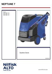
The DELTABOOSTER has been built up with<br />
an all-welded frame in a solid construction of<br />
stainless steel. The motor pumps have been<br />
suspended on a rubber damper with flexible<br />
connections to power and water.<br />
The water<br />
tank has two<br />
water inlets -<br />
one for cold<br />
and one for<br />
hot water. These inlets can<br />
be placed either on the left<br />
side or the right side as<br />
you require.<br />
The water tank has been<br />
placed at the top with the<br />
purpose of feeding the<br />
pumps with water under a<br />
certain pressure. Thus it<br />
will be possible to operate<br />
with water up to a temperature of<br />
75°C.<br />
The control system containing all the<br />
electronics for control has been<br />
arranged in a waterproof<br />
box of stainless steel<br />
placed at a thermal<br />
distance to the water<br />
tank. The door has been<br />
secured by two<br />
triangular locks and a<br />
lock in the main switch<br />
ensuring that the door<br />
can only be opened<br />
when the current has<br />
been switched off.<br />
The two sides of the frame contain the wire<br />
terminals and cables of the motor, which have<br />
been covered by a screw lid of water- and<br />
stainless steel. On the outside the machine has<br />
been covered with stainless steel plates. The<br />
front door can be opened either from the right<br />
or the left side as you require or be completely<br />
dismounted without using any tools. The motor<br />
pumps have been placed with the pump parts<br />
exposed to view to ease the access to<br />
inspecting the wearing parts of the pumpe.<br />
DELTABOOSTER_GB01<br />
Structure<br />
The pumps are 4<br />
cylinder axial piston<br />
pumps with solid<br />
ceramic pistons and<br />
valves of stainless<br />
steel. The pump has<br />
been prepared for a<br />
continuous working pressure of 210 bar.<br />
The DELTABOOSTER can be delivered with<br />
pressure settings from 90 to a max. of 160 bar<br />
according to your wishes.<br />
Before the delivery the DELTABOOSTER has<br />
been subjected to a 24 hours' optimal test and<br />
is therefore 100% ready for operation with no<br />
ajustments required.<br />
On delivery the DELTABOOSTER is fitted with<br />
2 Heavy Duty water inlet hoses<br />
and 1 pressure outlet hose for<br />
connection to the pipeline (arrow).<br />
Photo shows correct<br />
mounting of emergency stop<br />
valve at the top and test valve at<br />
the bottom.<br />
The DELTABOOSTER is<br />
fitted with 4 vibration<br />
absorbing rubber supports<br />
which can be adjusted<br />
separately so that the<br />
machine stands evenly and<br />
firmly.<br />
From machine<br />
For a further fixation to the floor, 2 or 4 fittings<br />
can be used (see illustration).<br />
B<br />
1
18<br />
7<br />
8<br />
9<br />
15<br />
14<br />
1: Connection of cold water supply<br />
2: Connection of hot water supply<br />
3: Filter housing drain<br />
4: Non-return valve HP outlet<br />
5: HP outlet hose for the pipeline<br />
6: Main switch<br />
7: Switch for control current<br />
8: Starting switch<br />
9: Cable connection to motor pumps<br />
10: Water inlet from water tank<br />
11: Pressure outlet to central manifold<br />
DELTABOOSTER_GB01<br />
DELTABOOSTER<br />
DELTABOOSTER<br />
13<br />
12<br />
16<br />
10 11<br />
Structure<br />
6<br />
20<br />
9<br />
17<br />
4<br />
5<br />
21<br />
1<br />
19<br />
12: Central manifold HP<br />
13: Overflow valve<br />
14: Distribution block, pressure system<br />
15: Pressure gauge HP<br />
16: Pressure switches<br />
17: Level indicator for pump lubricating oil<br />
18: Control panel<br />
19: Pressure equalizer (damper)<br />
20: Cable connection box<br />
21: Model tag<br />
3<br />
2<br />
B<br />
2
DELTABOOSTER_GB01<br />
4<br />
Structure<br />
5<br />
As it appears from the illustration, the<br />
whole front door (1) can be removed by<br />
turning both fasteners into horizontal<br />
position.<br />
The control system (2) is mounted at a<br />
distance to the water tank so that neither<br />
heat or cold is transferred from the tank to<br />
the power module box.<br />
The fans (4) of the motor provides the<br />
cooling. They take air from the back of the<br />
machine and press it forwards past the fins<br />
of the motor and on to the space between<br />
the water tank and the power module box.<br />
The internal overflow pipe of the water tank<br />
is connected to a rubber hose (3) which<br />
leads the water to the floor if a fault should<br />
arise in the control system.<br />
Each motor is suspended in four rubber<br />
dampers (5).<br />
On the pressure outlet of the machine a<br />
non-return valve (6) and a pressure<br />
accumulator (7) are mounted.<br />
7<br />
B<br />
3
DELTABOOSTER_GB01<br />
Structure<br />
The water tank seen from above and without cover.<br />
On the left side you will see the water inlet with the solenoid valves for hot and cold water<br />
respectively.<br />
On the right side you will see the interior of the water tank with the inlet pipes to the left.<br />
3<br />
(1) Solenoid valve (100 l/min at 1 bar) for cold water<br />
(2) Solenoid valve (135 l/min at 1 bar)) for hot water<br />
(3) Solenoid valve for pressure relief in case of interruption<br />
(4) Overflow, only the posterior valve is open (turning of tank)<br />
(5) Temperature sensor<br />
(6) 3 level switches - the lower for alarm for low water level<br />
(7) 6 suction pipes for the pumps covered by a steel wire netting<br />
(8) Inlet for return water from overflow valve mounted with a steel<br />
wire netting.<br />
The water tank has been constructed in accordance<br />
with very strict requirements to prevent water from<br />
being siphoned from the tank and back into the mains.<br />
As these rules do not apply in all countries, the tank<br />
has been fitted with knock-out pieces which can be<br />
removed if required.<br />
To reduce splashes from the water inlet pipes, the<br />
back of the water tank has been screened and fitted<br />
with glance off plates. Thus you will also avoid the<br />
ingress of air bubbles.<br />
The tank has been prepared for mounting with<br />
water inlet in either the left or the right side.<br />
Therefore the one of the overflow pipes has been<br />
sealed with a plug.<br />
The sucking ports for each pump are protected with<br />
a filter screen placed in a hollow at the bottom. The<br />
tank has been subjected to a modification (see<br />
Technical Information no. 293, page I4).<br />
B<br />
4
0<br />
DELTABOOSTER_GB01<br />
Structure<br />
The power module box is made of stainless steel in<br />
accordance with very strict requirements for safety and with<br />
a tightness of IP55. This version is mounted with 6 pumps<br />
and with the latest version of circuit board (see Technical<br />
Information no. 307, page I6).<br />
The power supply cable is lead from the back of the<br />
DELTABOOSTER through the cable sleeve (1).<br />
(2) The main switch also works as a lock for the door and is capable of breaking max. 125 amp.<br />
Therefore the pre-fuse must not exceed this level. From the main switch the connection is<br />
distributed on to (3).<br />
(3) Current limiters, 2 pcs., are automatic safety cut-outs (in case of a short circuit). From here<br />
the connection is lead on to (4) by means of the integrated conductor rail.<br />
(4) Overload switches secure each of the motors against overload. Adjusted to the full load<br />
current.<br />
(5) The contactors of the motors are motor relays with a 24 volt coil.<br />
(6) The cables for the motors are lead via the left and the right channels to the motor terminals.<br />
(7) Primary fuses F1 F2 for protection of the steering transformer against overload.<br />
(8) Steering transformer 24 volt 10 amp. Note that O is connected to the frame (safety requirement)<br />
6<br />
8<br />
16<br />
15<br />
13 14<br />
19<br />
9<br />
11<br />
12<br />
10<br />
7<br />
4<br />
(9) X1. 24 volt supply from the steering transformer via turnable knob on the front door<br />
(10) X4. 24 volt control system for the motor relays (5)<br />
(11) X2. signal lead from the overload switches of the motor (4)<br />
(12) X3. signal lead from the temperature sensors of the motors placed in the windings<br />
(13) X6. 24 volt control current for the solenoid valves for hot and cold inlet water<br />
(14) X5. 24 volt supply to by-pass valve on tank + supply to softener pump<br />
(15) X7. signal lead from level sensors in tank, by-pass switch and pressure switches<br />
(16) X8. 24 volt start signal, level in tank (alarm), temperature sensor in tank<br />
(17) 24 volt hour counters connected to the contactors<br />
(18) earth connection to frame - please note that the whole back plate and the circuit board are<br />
connected to the frame<br />
(19) flat cable connection to PCB of lamp for display and PCB of remote control<br />
3<br />
17<br />
5 5<br />
2<br />
18<br />
4<br />
1 6<br />
B<br />
5
DELTABOOSTER_GB01<br />
Structure<br />
From the control system the cables are lead to the<br />
motors (3) via the panels in the sides, through the<br />
cable boxes and the flexible hoses (1) in the left and<br />
also the right side.<br />
From the motor the cables are lead to the terminal (6)<br />
through a flexible silicone hose (4) which has been<br />
made tight by means of hose clamps.<br />
This terminal (6) has been connected in a<br />
star with the neutral point in the terminals<br />
marked Y.<br />
The terminals 1 and 2 make up the<br />
connection for the temperature sensor<br />
with the motor cables marked 9 and 14.<br />
(5) The earth/frame connection for the<br />
motor.<br />
B<br />
6
DELTABOOSTER_GB01<br />
Structure<br />
Appeal !<br />
If you find that some information is missing in this section or something is not quite clear, please<br />
describe the matter on this page and forward it to TST - fax. +45 7218 2246.<br />
B<br />
7
DELTABOOSTER_GB01<br />
Function<br />
The flow system is illustrated in pressure-relieved disconnected condition. The water<br />
tank, however, is full. Of practical reasons only 3 of the pumps appear disticntly. The<br />
reference numbers will be used in the rest of the manual. (P1), (P2), and (P3) are the<br />
pumps.<br />
;<br />
;<br />
; !<br />
8<br />
8<br />
8<br />
# �������# ��������� ��� ����� # �� % # ���<br />
* = H<br />
2 !<br />
2<br />
2<br />
8<br />
�<br />
8 !<br />
8 !<br />
8 !<br />
0<br />
* *<br />
8 "<br />
(Y1) & (Y2) Solenoid valves for hot and cold water<br />
(Y3) Relief valve, relieves the external pipeline of pressure when the machine is<br />
stopped<br />
(B1) & (B2) Pressure switches with high and low adjustment. Primary function: to start<br />
up the pumps<br />
(B4) Overflow switch closes when there is a flow. Function: to stop the pumps<br />
(B5) Level switch closes at max. water level. Function: to stop the water inlet.<br />
(B6) Level switch opens when the water level is low. Function: to start the water inlet<br />
(B7) Temperature sensor max./min. temperature. Function: to control Y1 & Y2<br />
(B8) Level switch closes if the water level is extremely low. Function: to stop the machine<br />
(V1) Overflow valve opens at a pressure > the working pressure. Function: to lead water<br />
to the water tank<br />
(V2) Safety valve. One on each pump. Opens at working pressure + 40 bar<br />
(V3) Non-return valve. One for each pump. Function: To prevent water flow from other pumps<br />
(V4) Main non-return valve. Function: to protect against backflash and water flow from<br />
other plants.<br />
* "<br />
2 $<br />
2 #<br />
2 "<br />
* #<br />
* $<br />
* &<br />
* %<br />
C<br />
Disconnected<br />
1
DELTABOOSTER_GB01<br />
Function<br />
The machine is in operation and one user works with a standard nozzle of size 006<br />
corresponding to 17.3 l/min. (1038 l/h) or the water volume of one pump.<br />
The water temperature is set at cold, meaning that only the solenoid valve for cold water<br />
is activated when there is a requirement for water.<br />
*<br />
*<br />
0<br />
�<br />
!<br />
)<br />
)<br />
)<br />
; !<br />
Pump P2 is in operation. The pressure in the system is 160 bar. The water is drawn from<br />
the tank and the pump pumps it through the non-return valve into the central pipe,<br />
through the main non-return valve and into the system. On the display the two lights of<br />
the pressure switches (B1) and (B2) are on, and the light of the pressure relief valve (Y3)<br />
signals that the valve is closed.<br />
(B6) indicates that the level in the water tank is not so low that more more water is<br />
required. The system is stable.<br />
To be continued on page 3.<br />
* $<br />
$<br />
#<br />
"<br />
0 � J + � � @<br />
# �������# ��������� ��� ����� # �� % # ���<br />
� � A K I A H % � � � E �<br />
* = H<br />
2<br />
�<br />
0<br />
C<br />
One User Operation<br />
* $<br />
"<br />
2
DELTABOOSTER_GB01<br />
Function<br />
From the situation on page 2. The water level in the tank is now so low that the (B6)<br />
switch opens, the light goes out and thus the solenoid valve Y2 is activated and cold<br />
water is lead into the tank. Yet another user with nozzle 006 has started a consumption.<br />
;<br />
*<br />
0<br />
�<br />
!<br />
)<br />
)<br />
)<br />
C<br />
Operation, User No. 2, starts<br />
The situation is that (P2) is running, user no. two starts a consumption. Thus the pressure<br />
in the systems drops under the adjustment of the pressure switch (B1), the light goes out<br />
and gives signal to start the next pump, which - in this case - is pump (P3).<br />
The pressure is re-established. The light of pressure switch (B1) will then turn on and the<br />
operation of the system is stable.<br />
To be continued on page 4.<br />
$<br />
#<br />
"<br />
0 � J + � � @<br />
;<br />
# �������# ��������� ��� ��� � # �� % # ���<br />
* = H<br />
2 !<br />
2<br />
�<br />
*<br />
* $<br />
3
DELTABOOSTER_GB01<br />
Function<br />
From the situation on page 3.<br />
The water tank is now almost full. At the moment the level switch (B5) closes, the light<br />
will turn on and the filling stops. A user has just ended his consumption.<br />
� � � � � ��<br />
Unstable<br />
� � H<br />
� � L<br />
Stable<br />
� �<br />
� �<br />
H<br />
L<br />
� �<br />
3<br />
2<br />
1<br />
3<br />
2<br />
1<br />
A<br />
A<br />
A<br />
A<br />
A<br />
A<br />
� �<br />
6<br />
5<br />
4<br />
6<br />
5<br />
4<br />
25.......50.........100...120.....150..175...200<br />
Bar<br />
C<br />
Operation, User No. 2 stops<br />
At the moment a user stops, the pressure will increase by approx. 10 bar and the unused<br />
water, which in this case is the water volume of one pump, will now be lead back to the<br />
water tank through the overflow valve (V1) and the flow valve (B4).<br />
Via a timer (B4) will give signal to stop one pump (P2) which will stop after approx. 15<br />
sec. The stable operation will continue with one user.<br />
When the last user stops the same will happen as described above, and the last pump<br />
will stop. Now the machine is standing with pressure (working pressure) ready for operation.<br />
At the moment a user starts a consumption, the pressure will drop to the level of the<br />
pressure switch (B2) which is approx. 25 bar as standard. That means that the lights (B1)<br />
and (B2) goes out before the start signal to a pump is released, and one pump will start.<br />
If it takes more than approx. 3 sec. to build up the pressure to (B1) level, another pump<br />
will be started. This situation often appears in big pipelines or if there is air in the system.<br />
� �<br />
� �<br />
L<br />
� �<br />
� �<br />
� �<br />
H<br />
� �<br />
� �<br />
4
DELTABOOSTER_GB01<br />
"<br />
2 K � F<br />
8<br />
!<br />
� � � H A J K H � L = � L A<br />
8<br />
� K J<br />
The water volume of each<br />
pump is pressed through a<br />
non-return valve (V2) into<br />
the common central pipe.<br />
When there is a<br />
consumption, the water is<br />
pressed on through the<br />
valve flap (7) of the main non-return valve<br />
(V4) and into the pipeline outside the<br />
machine.<br />
The pressure switches (B1 and B2), pressure<br />
gauge and pressure accumulator are<br />
connected to the pipeline outside the<br />
machine. The pressure switches are<br />
identical but differently adjusted with the<br />
setting screw (10).<br />
The function is simple. A piston (8) presses<br />
against a spring and with an arm on the<br />
microswitch (9) which closes at the<br />
adjusted pressure.<br />
Function<br />
%<br />
2 K � F I 2 E F A I O I<br />
8 "<br />
'<br />
*<br />
#<br />
* "<br />
# �������# ��������� ��� ����� # �� % # ���<br />
* = H<br />
&<br />
C<br />
Valve System<br />
6 = � �<br />
When the consumption stops, the<br />
water is lead from the pumps to the<br />
overflow valve (V1) which opens by<br />
pressing a piston (2) away from the seat<br />
(1) towards the spring washers (3).<br />
The water proceeds into the flow switch<br />
(B4) where it presses a piston with a magnet<br />
up against a reed-switch which then<br />
closes.<br />
The water then runs into the tank and<br />
further on as long as the machine is<br />
running in by-pass mode.<br />
$<br />
*<br />
2 H A I I K H A I M E J ? D<br />
5
DELTABOOSTER_GB01<br />
Function<br />
The diagram illustrates the control functions of the water tank in some given situations -<br />
a, b, c, d, e.<br />
The water temperature is adjusted to 55°C.<br />
The top curve illustrates the actual temperature of the water tank.<br />
Temp Sens, the line indicates that the sensor measures a deviation from the set value.<br />
Adjust, the line indicates that the electronics requires an adjustment of the temperature.<br />
Level Alarm, the line indicates that the level in the water tank has reached the lowest<br />
level (machine stops).<br />
Level High , the line indicates that the water tank is full (stop of water intake).<br />
Level Low, the line indicates that more water is required (start of water intake).<br />
Valve Cold, the line indicates that the solenoid valve with cold water is open.<br />
Valve Hot, the line indicates that the solenoid valve with hot water is open.<br />
* %<br />
* &<br />
* #<br />
* $<br />
;<br />
;<br />
+ �<br />
9 = J A H<br />
J A � F<br />
J = � �<br />
&<br />
$<br />
"<br />
6 A � F 5 A � I<br />
) � K I J<br />
� A L A � ) � = H �<br />
� A L A � 0 E C D<br />
� A L A � � � M<br />
8 = � L A + � � @<br />
8 = � L A 0 � J<br />
= > ? @ A<br />
� = N " I A ?<br />
C<br />
Water Tank, Control<br />
a: There has been no consumption on the machine, and the temperature has therefore<br />
fallen to approx. 20°C. (B5) shows that the water tank is full.<br />
b: A consumption has started. (B6) requires more water. (B7) requires a higher temperature,<br />
the adjustment is activated and Y1 opens.<br />
c: The temperature set is reached. (B5) is still not activated, (Y2) gives access to the<br />
cold water to stabilize the temperature.<br />
d: (B6) requires more water and (B7) requires hot water. The water supply is unsufficient<br />
to fill the tank. After 4 seconds in this condition, the temperature adjustment will be<br />
interrupted and (Y1) as well as (Y2) are kept open irrespective of the water temperature<br />
(on the display of the machine, the temperature light is on).<br />
e: The water supply is insufficient. (B8) is activated and the machine stopped.<br />
6
DELTABOOSTER_GB01<br />
Function<br />
C<br />
Pressure Control<br />
The diagram illustrates the pressure regulation system of the machine in some given<br />
situations - a, b, c, and e.<br />
The working pressure is 160 bar and the by-pass pressure approx. 175 bar. The curve<br />
indicates the system pressure.<br />
Flow out - indicates that there is a consumption out of the machine.<br />
Press 120 - indicates that (B1) is active and requires more pressure.<br />
Press 25 - indicates that (B2) is active and requires more pressure.<br />
Flow bypass - indicates that (B4) is active and requires less water.<br />
Operation - indicates that one er more pumps are in operation.<br />
Start pump - indicates a requirement from (B1) and/or (B2) to start a pump.<br />
Stop Pump - indicates a requirement from (B4) to stop a pump.<br />
= > ? @ A<br />
*<br />
*<br />
* "<br />
> = H<br />
% #<br />
$<br />
� E � A<br />
F H A I I K H A<br />
� � � M � K J<br />
2 H A I I<br />
2 H A I I #<br />
� � � M > O F = I I<br />
� F A H = J E � �<br />
5 J = H J F K � F<br />
5 J � F F K � F<br />
#<br />
# I A ?<br />
! I A ?<br />
a: The machine has just been started manually and is building up a pressure. If (B2)<br />
pressure level (25 bar) is reached within 2 sec., only one pump will start, as in this<br />
case. As there is no consumption, the water volume returns from one pump to the tank<br />
through (B4). If this condition is kept for 15 sec., a stop signal will be sent to a pump.<br />
b: Machine is now stopped and ready for operation with pressure in the whole system<br />
(working pressure).<br />
c: A consumption has started and as the pressure falls to (B2) level, a signal for start is<br />
sent to a pump which increases the pressure to working pressure (160 bar).<br />
d: Yet another user has started a consumption. The pressure goes down under (B1)<br />
level (120 bar). (B1) becomes active and sends a signal to start one more pump. If the<br />
pressure is not increased over (B1) level within 3 sec. another pump will start.<br />
e: An extremely heavy consumption has started (pipe burst). The pressure falls below<br />
(B2) level. All pumps stop one by one. If the pressure does not rise to a level over (B2)<br />
within 25 sec., the whole plant will stop and indicate a fault condition.<br />
7
DELTABOOSTER_GB01<br />
Function<br />
The control panel has been built-up as a schematic drawing of the DELTABOOSTER.<br />
A number of warning lamps indicate the operational condition of the plant and any fault<br />
situations. The warning lamps are divided into three categories:<br />
Green: indicates a motor or a valve in operation.<br />
Yellow: indicates an activated sensor (pressure switch, flow switch, level switch).<br />
Red: indicates a serious fault (leakage, overheating, low water level).<br />
� �<br />
� �<br />
� �<br />
� �<br />
� �<br />
H<br />
L<br />
� �<br />
3<br />
2<br />
1<br />
� �<br />
� �<br />
A<br />
A<br />
A<br />
� �<br />
� � � � � � � �<br />
� �<br />
If a fault arises, the concerned red light will turn on and the plant stop. The status of the<br />
opereational condition of the machine at the moment the fault arised will be kept until the<br />
current is switched off. Faults on the individual pumps can be by-passed so that the other<br />
pumps can continue their operation. This is achieved by stopping and re-starting the<br />
machine.<br />
Y1 and Y2 turn on when the cold/hot water inlet is open.<br />
Y3 turns on when the relief valve is closed.<br />
E1 and E2 turn on if there is a leakage on the system.<br />
B1 and B2 turn on when the pressure is higher than the setting point of the pressure<br />
switches.<br />
B4 turns on when the flow switches registrate a return of water to tank (over 10 l/min.).<br />
Y4 turns on when the temperature adjustment is on. Flashes if the water supply is insufficient.<br />
E3 turns on in case of an illegal sensor combination. Example: B1 turn on but not B2<br />
(see diagram on page C10).<br />
B7 turns on if the temperature of the water in the water tank is too high, max. 80°C.<br />
B8 turns on if the water level is too low.<br />
B5 and B6 turn on if the water level is either too high or too low.<br />
Mx turns on when the motor pump is in operation.<br />
Qx turns on in the case of an overload or phase breaking (motor protection disconnects).<br />
Kx turns on if the temperature in the windings is too high (over 160°C).<br />
� �<br />
� �<br />
� �<br />
6<br />
5<br />
4<br />
C<br />
Display<br />
8
DELTABOOSTER_GB01<br />
Function<br />
"DIP" switch Test socket<br />
The configuration of the DELTABOOSTER<br />
is set at the control with an eight-pole DIPswitch.<br />
This position applies to a 3-pump<br />
plant.<br />
The switches 1-6 are set at ON if the<br />
DELTABOOSTER has 6 pumps.<br />
The switches 7 and 8 are for the linking of<br />
one er more plants (see Linking on page<br />
I2).<br />
On single machines both switches are set<br />
at ON.<br />
Temperature adjustment (water temperature<br />
in tank). The turnable knob can either<br />
be set at OFF (click) as shown with the<br />
scale facing downwards, or at the required<br />
temperature.<br />
� � �<br />
EEEEEEEEEEEEEEE # EEEEEEEEEEEEEE # EEEEEEEEEEEEEE % # �<br />
F1<br />
For testing of the lamp function and the<br />
output signals, a 3-pin plug S 102 has<br />
been placed on the printed circuit board.<br />
By moving the socket to the upper 2 pins,<br />
the circuit board makes a self-test. At first<br />
the lights go on one by one at an interval<br />
of 1 second. Then Y1, Y1 and Y3 and each<br />
motor is activated one by one.<br />
Note: Do not forget to turn off the water<br />
supply, as there will be a risk of overflow.<br />
The fuse (F1) on the circuit board is for<br />
protection against fire. If this fuse blows,<br />
the circuit board has become defective.<br />
C<br />
Printed Circuit Board<br />
5 5<br />
9
Con-<br />
dition<br />
DELTABOOSTER_GB01<br />
B4<br />
By-pass<br />
switch<br />
Pump<br />
operation<br />
B2<br />
Pres.<br />
( low)<br />
Function<br />
The diagram illustrates the various situations that theoretically may arise.<br />
B1<br />
Pres.<br />
( high)<br />
0 0 0 0 0<br />
Status<br />
Start<br />
signal<br />
Delay<br />
Sec.<br />
Function<br />
0 , 1 Manual<br />
start<br />
pump<br />
1 0 1 0 1 Illegal 1 5 Stop<br />
plant<br />
( fault)<br />
2 0 1 1 0<br />
3 0 1 1 1<br />
Consump-<br />
tion<br />
Consump-<br />
tion<br />
2 Start<br />
pumps<br />
15Operationstable 4 0 1 0 0 Leakage 2 5 Stop<br />
plant<br />
( fault)<br />
5 1 0 0 0 Illegal 1 5 Stop<br />
plant<br />
( fault)<br />
6 1 0 0 1 Illegal 1 5 Stop<br />
plant<br />
( fault)<br />
7 1 0 1 0 Illegal 1 5 Stop<br />
plant<br />
( fault)<br />
8 1 0 1 1 Illegal 1 5 Stop<br />
plant<br />
( fault)<br />
9 1 1 0 1 Illegal 1 5 Stop<br />
plant<br />
( fault)<br />
10 1 1 1 0 Illegal 1 5 Stop<br />
plant<br />
( fault)<br />
111 1 1 1 By-pass 15 Stop<br />
one<br />
pump<br />
C<br />
Working Diagram<br />
As an example condition 4 illustrates: Pump operation (one or more pumps in operation).<br />
B1 and B2 are not activated, meaning that the pressure is lower than 25 bar and there is<br />
no by-passing. Thus there will be no outlet of water from the system and there must be a<br />
leakage. The plant will be stopped after 25 seconds in this condition.<br />
Condition 10 illustrates that water is by-passing, a pump is in operation and there is a<br />
system pressure of at least 25 bar. This is only possible if the overflow valve V1 is<br />
adjusted lower than B1, i.e. an illegal situation.<br />
10
DELTABOOSTER_GB01<br />
Function<br />
Appeal !<br />
If you find that some information is missing in this section or something is not quite clear,<br />
please describe the matter on this page and forward it to TST - fax. +45 7218 2246.<br />
C<br />
11
DELTABOOSTER_GB01<br />
Trouble-shooting<br />
To ensure a problem-free operation, the following requirements must be fulfilled:<br />
1. Machine and pipeline must be free of air and tight.<br />
2. The water temperature must not exceed 80°C.<br />
3. The water must be without any impurities as for instance running sands > 50 µ.<br />
4. The water supply must always be sufficient.<br />
5. The ambient temperature must not exceed 40°C.<br />
6. Variations in the mains voltage must be max. ±10% of the rated value.<br />
D<br />
Functional Requirements<br />
If the above-mentioned requirements are met, it must be possible, at any time, to tap off 17 l/min. x<br />
the number of pumps under a steady pressure of 160 bar (120 bar in the case of reduced plants)<br />
on a pipeline connected to a DELTABOOSTER and equipped with original standard nozzles.<br />
If these requirements are met and you still experience operational break-downs, there are faults<br />
on the system.<br />
1
2<br />
DELTABOOSTER_GB01<br />
D<br />
Trouble-shooting<br />
Starting-up Problems<br />
The first time a DELTABOOSTER is started up, either because it is a new plant or because it has<br />
undergone some changes or a repair, the following typical faults may occour:<br />
:<br />
m<br />
o<br />
t<br />
p<br />
m<br />
y<br />
S<br />
s<br />
e<br />
o<br />
d<br />
e<br />
n<br />
i<br />
h<br />
c<br />
a<br />
m<br />
e<br />
h<br />
T<br />
.<br />
y<br />
a<br />
l<br />
p<br />
s<br />
i<br />
d<br />
e<br />
h<br />
t<br />
n<br />
i<br />
t<br />
h<br />
g<br />
i<br />
l<br />
o<br />
N<br />
.<br />
l<br />
a<br />
n<br />
g<br />
i<br />
s<br />
g<br />
n<br />
i<br />
t<br />
r<br />
a<br />
t<br />
s<br />
a<br />
o<br />
t<br />
t<br />
c<br />
a<br />
e<br />
r<br />
t<br />
o<br />
n<br />
y<br />
l<br />
l<br />
a<br />
u<br />
n<br />
a<br />
m<br />
y<br />
b<br />
e<br />
g<br />
a<br />
t<br />
l<br />
o<br />
v<br />
s<br />
n<br />
i<br />
a<br />
m<br />
e<br />
h<br />
t<br />
k<br />
c<br />
e<br />
h<br />
C<br />
.<br />
h<br />
c<br />
t<br />
i<br />
w<br />
s<br />
r<br />
o<br />
t<br />
o<br />
m<br />
a<br />
g<br />
n<br />
i<br />
s<br />
s<br />
e<br />
r<br />
p<br />
:<br />
1<br />
n<br />
o<br />
s<br />
a<br />
e<br />
R .<br />
e<br />
n<br />
i<br />
h<br />
c<br />
a<br />
m<br />
e<br />
h<br />
t<br />
r<br />
o<br />
f<br />
e<br />
g<br />
a<br />
t<br />
l<br />
o<br />
v<br />
o<br />
N<br />
y<br />
l<br />
l<br />
a<br />
u<br />
n<br />
a<br />
m<br />
y<br />
b<br />
e<br />
g<br />
a<br />
t<br />
l<br />
o<br />
v<br />
s<br />
n<br />
i<br />
a<br />
m<br />
e<br />
h<br />
t<br />
k<br />
c<br />
e<br />
h<br />
C<br />
.<br />
h<br />
c<br />
t<br />
i<br />
w<br />
s<br />
r<br />
o<br />
t<br />
o<br />
m<br />
a<br />
g<br />
n<br />
i<br />
s<br />
s<br />
e<br />
r<br />
p<br />
.<br />
2<br />
F<br />
d<br />
n<br />
a<br />
1<br />
F<br />
s<br />
e<br />
s<br />
u<br />
f<br />
k<br />
c<br />
e<br />
h<br />
C<br />
:<br />
2<br />
n<br />
o<br />
s<br />
a<br />
e<br />
R .<br />
g<br />
n<br />
i<br />
s<br />
s<br />
i<br />
m<br />
r<br />
e<br />
m<br />
r<br />
o<br />
f<br />
s<br />
n<br />
a<br />
r<br />
t<br />
m<br />
o<br />
r<br />
f<br />
t<br />
l<br />
o<br />
v<br />
4<br />
2 .<br />
r<br />
e<br />
m<br />
r<br />
o<br />
f<br />
s<br />
n<br />
a<br />
r<br />
t<br />
n<br />
o<br />
3<br />
F<br />
e<br />
s<br />
u<br />
f<br />
k<br />
c<br />
e<br />
h<br />
C<br />
m<br />
o<br />
t<br />
p<br />
m<br />
y<br />
S<br />
t<br />
o<br />
n<br />
s<br />
e<br />
o<br />
d<br />
e<br />
n<br />
i<br />
h<br />
c<br />
a<br />
M<br />
.<br />
K<br />
O<br />
s<br />
i<br />
y<br />
a<br />
l<br />
p<br />
s<br />
i<br />
d<br />
n<br />
i<br />
t<br />
h<br />
g<br />
i<br />
L<br />
.<br />
l<br />
a<br />
n<br />
g<br />
i<br />
s<br />
g<br />
n<br />
i<br />
t<br />
r<br />
a<br />
t<br />
s<br />
a<br />
o<br />
t<br />
t<br />
c<br />
a<br />
e<br />
r<br />
d<br />
r<br />
a<br />
o<br />
b<br />
t<br />
i<br />
u<br />
c<br />
r<br />
i<br />
c<br />
n<br />
o<br />
h<br />
c<br />
t<br />
i<br />
w<br />
s<br />
o<br />
r<br />
c<br />
i<br />
m<br />
k<br />
c<br />
e<br />
h<br />
C<br />
.<br />
)<br />
9<br />
e<br />
g<br />
a<br />
p<br />
C<br />
n<br />
o<br />
i<br />
t<br />
c<br />
e<br />
s<br />
e<br />
e<br />
s<br />
(<br />
:<br />
m<br />
o<br />
t<br />
p<br />
m<br />
y<br />
S<br />
.<br />
e<br />
s<br />
i<br />
o<br />
n<br />
a<br />
e<br />
k<br />
a<br />
m<br />
d<br />
n<br />
a<br />
e<br />
k<br />
a<br />
h<br />
s<br />
s<br />
p<br />
m<br />
u<br />
p<br />
e<br />
h<br />
T<br />
.<br />
g<br />
n<br />
i<br />
t<br />
a<br />
u<br />
t<br />
c<br />
u<br />
l<br />
f<br />
d<br />
n<br />
a<br />
w<br />
o<br />
l<br />
o<br />
o<br />
t<br />
s<br />
i<br />
e<br />
r<br />
u<br />
s<br />
s<br />
e<br />
r<br />
p<br />
e<br />
h<br />
T<br />
.<br />
y<br />
l<br />
e<br />
t<br />
a<br />
i<br />
d<br />
e<br />
m<br />
m<br />
i<br />
e<br />
n<br />
i<br />
h<br />
c<br />
a<br />
m<br />
e<br />
h<br />
t<br />
p<br />
o<br />
t<br />
S<br />
:<br />
1<br />
n<br />
o<br />
s<br />
a<br />
e<br />
R<br />
.<br />
s<br />
p<br />
m<br />
u<br />
p<br />
e<br />
h<br />
t<br />
n<br />
i<br />
r<br />
i<br />
A<br />
e<br />
h<br />
t<br />
n<br />
e<br />
s<br />
o<br />
o<br />
l<br />
,<br />
p<br />
a<br />
t<br />
r<br />
e<br />
t<br />
a<br />
w<br />
e<br />
h<br />
t<br />
n<br />
o<br />
n<br />
r<br />
u<br />
T<br />
e<br />
h<br />
t<br />
t<br />
r<br />
a<br />
t<br />
s<br />
,<br />
s<br />
p<br />
m<br />
u<br />
p<br />
e<br />
h<br />
t<br />
f<br />
o<br />
s<br />
w<br />
e<br />
r<br />
c<br />
s<br />
g<br />
n<br />
i<br />
t<br />
n<br />
e<br />
v<br />
o<br />
t<br />
t<br />
n<br />
a<br />
l<br />
p<br />
e<br />
h<br />
t<br />
t<br />
c<br />
e<br />
j<br />
b<br />
u<br />
s<br />
y<br />
a<br />
m<br />
u<br />
o<br />
y<br />
(<br />
e<br />
n<br />
i<br />
h<br />
c<br />
a<br />
m<br />
e<br />
g<br />
a<br />
p<br />
C<br />
n<br />
o<br />
i<br />
t<br />
c<br />
e<br />
s<br />
n<br />
i<br />
e<br />
m<br />
m<br />
a<br />
r<br />
g<br />
o<br />
r<br />
p<br />
t<br />
s<br />
e<br />
t<br />
e<br />
h<br />
t<br />
.<br />
)<br />
9<br />
:<br />
2<br />
n<br />
o<br />
s<br />
a<br />
e<br />
R<br />
e<br />
r<br />
u<br />
s<br />
s<br />
e<br />
r<br />
p<br />
r<br />
o<br />
s<br />
e<br />
v<br />
l<br />
a<br />
v<br />
n<br />
o<br />
i<br />
t<br />
c<br />
u<br />
s<br />
e<br />
h<br />
t<br />
n<br />
i<br />
t<br />
r<br />
i<br />
D<br />
.<br />
s<br />
e<br />
v<br />
l<br />
a<br />
v<br />
e<br />
h<br />
t<br />
t<br />
a<br />
h<br />
t<br />
k<br />
c<br />
e<br />
h<br />
c<br />
d<br />
n<br />
a<br />
s<br />
e<br />
v<br />
l<br />
a<br />
v<br />
e<br />
h<br />
t<br />
n<br />
a<br />
e<br />
l<br />
C<br />
.<br />
y<br />
l<br />
t<br />
c<br />
e<br />
r<br />
r<br />
o<br />
c<br />
d<br />
e<br />
n<br />
o<br />
i<br />
t<br />
i<br />
s<br />
o<br />
p<br />
s<br />
i<br />
k<br />
n<br />
a<br />
t<br />
e<br />
h<br />
t<br />
n<br />
i<br />
r<br />
e<br />
t<br />
l<br />
i<br />
f<br />
:<br />
m<br />
o<br />
t<br />
p<br />
m<br />
y<br />
S .<br />
p<br />
u<br />
t<br />
r<br />
a<br />
t<br />
s<br />
s<br />
p<br />
m<br />
u<br />
p<br />
e<br />
r<br />
o<br />
m<br />
r<br />
o<br />
4<br />
.<br />
d<br />
e<br />
s<br />
o<br />
l<br />
c<br />
e<br />
r<br />
a<br />
s<br />
p<br />
a<br />
t<br />
l<br />
l<br />
a<br />
t<br />
a<br />
h<br />
t<br />
k<br />
c<br />
e<br />
h<br />
C<br />
n<br />
i<br />
a<br />
m<br />
e<br />
h<br />
t<br />
e<br />
s<br />
o<br />
l<br />
c<br />
o<br />
t<br />
y<br />
r<br />
a<br />
s<br />
s<br />
e<br />
c<br />
e<br />
n<br />
e<br />
b<br />
y<br />
a<br />
m<br />
t<br />
I<br />
.<br />
e<br />
v<br />
l<br />
a<br />
v<br />
:<br />
1<br />
n<br />
o<br />
s<br />
a<br />
e<br />
R .<br />
e<br />
n<br />
i<br />
l<br />
e<br />
p<br />
i<br />
p<br />
e<br />
h<br />
t<br />
n<br />
i<br />
r<br />
i<br />
A .<br />
e<br />
n<br />
i<br />
l<br />
e<br />
p<br />
i<br />
p<br />
e<br />
l<br />
o<br />
h<br />
w<br />
e<br />
h<br />
t<br />
t<br />
n<br />
e<br />
V<br />
:<br />
2<br />
n<br />
o<br />
s<br />
a<br />
e<br />
R<br />
g<br />
n<br />
o<br />
l<br />
,<br />
y<br />
n<br />
a<br />
m<br />
y<br />
l<br />
e<br />
t<br />
a<br />
n<br />
o<br />
i<br />
t<br />
r<br />
o<br />
p<br />
o<br />
r<br />
p<br />
s<br />
i<br />
d<br />
e<br />
r<br />
a<br />
e<br />
r<br />
e<br />
h<br />
T<br />
.<br />
d<br />
e<br />
t<br />
c<br />
e<br />
n<br />
n<br />
o<br />
c<br />
s<br />
e<br />
s<br />
o<br />
h<br />
d<br />
e<br />
t<br />
c<br />
e<br />
n<br />
n<br />
o<br />
c<br />
f<br />
o<br />
r<br />
e<br />
b<br />
m<br />
u<br />
n<br />
e<br />
h<br />
t<br />
e<br />
c<br />
u<br />
d<br />
e<br />
R<br />
.<br />
m<br />
u<br />
m<br />
i<br />
n<br />
i<br />
m<br />
a<br />
o<br />
t<br />
s<br />
e<br />
s<br />
o<br />
h
DELTABOOSTER_GB01<br />
Trouble-shooting<br />
Red light turns on - machine does not start up<br />
Symptom Reason Check<br />
Temperature in tank > 80°C Disconnect plug X8 from circuit board A1<br />
Temperature sensor B7 defective/<br />
short-circuited/ interrupted 7<br />
8 Ω<br />
See technical data, page A7<br />
Level switch in B6 or connection Disconnect plug X7 from circuit board<br />
defective/interrupted/sticks. In case of a full<br />
11 tank, B6 must<br />
12 Ω be connected.<br />
See page C1<br />
Level switch B8 or connection Disconnect plug X8 from circuit board<br />
defective/short-circuited/blocked/placed In case of a full<br />
wrongly. 09 tank, B8 must<br />
10 Ω be disconnected.<br />
See page C1<br />
Overflow switch B4 or connection Disconnect plug X7 from circuit board.<br />
defective/short-circuited/stuck. OK if connection<br />
7 broken off.<br />
8 Ω<br />
Overflow switch - see page E11<br />
D<br />
Pressure switch (HP) B1 or supply Disconnect plug X7 from circuit board.<br />
lines short-circuited/stuck. In pressure-relieved<br />
1 condition, broken<br />
2 Ω connection must<br />
appear.<br />
Pressure switch - see page E13<br />
Motor protection Q1 disconnected. Adjustment according to model tag.<br />
Voltage too low. Motor short-circuited. Measurement of insulations<br />
Motor missing phase. and winding resistance<br />
Motor protection adjusted too low.<br />
Water leakage<br />
See page F4<br />
Starting-up Problems<br />
3
DELTABOOSTER_GB01<br />
Trouble-shooting<br />
Display-status<br />
Re-start not possible: See “Starting-up problems”.<br />
Re-start possible: If the plant stops during operation, the status of various signal lamps will be stored on<br />
the display for function indication so that the reason of the stop can be reconstructed.<br />
Therefore it is of a great help to note this status before trying to re-start the plant. When attempting to<br />
re-start the plant, the status will be deleted.<br />
Please make a copy of this page, place the copy over the display of the machine and tick off the<br />
illuminated lamps. Send the fax page to your nearest technical supporter.<br />
;<br />
;<br />
-<br />
*<br />
*<br />
0<br />
�<br />
� N<br />
!<br />
-<br />
3 N<br />
)<br />
)<br />
)<br />
� N<br />
; "<br />
- !<br />
; !<br />
* %<br />
Pressure gauge, bar: ________ Steady _____ Falling _____<br />
D<br />
Interruption of Operation<br />
Comments: ______________________________________________________________________<br />
______________________________________________________________________<br />
Sender: ______________________________________________________________________<br />
* &<br />
* "<br />
* #<br />
* $<br />
$<br />
#<br />
"<br />
4
DELTABOOSTER_GB01<br />
Trouble-shooting<br />
Symptom: The machine stops shortly after start and display illustrates status.<br />
The examples below may vary from the actual status of the machine, as for instance the number of<br />
pumps in operation.<br />
Status Reason <strong>Repair</strong><br />
;<br />
;<br />
;<br />
;<br />
;<br />
-<br />
;<br />
-<br />
*<br />
*<br />
*<br />
*<br />
-<br />
*<br />
*<br />
0<br />
0<br />
�<br />
�<br />
0<br />
�<br />
� N<br />
!<br />
� N<br />
!<br />
� N<br />
!<br />
-<br />
-<br />
3 N<br />
)<br />
)<br />
)<br />
3 N<br />
)<br />
)<br />
)<br />
-<br />
3 N<br />
)<br />
)<br />
)<br />
� N<br />
� N<br />
; " - ! * % * &<br />
; !<br />
; " - ! * % * &<br />
� N<br />
; !<br />
; " - ! * % * &<br />
; !<br />
* "<br />
* "<br />
* "<br />
* #<br />
* $<br />
* #<br />
* $<br />
* #<br />
* $<br />
$<br />
$<br />
#<br />
"<br />
#<br />
"<br />
$<br />
#<br />
"<br />
Pressure switch (LP) B2 Disassemble, clean and<br />
out of operation lubricate pressure switch<br />
B2.<br />
Check cable connection.<br />
Replace microswitch.<br />
See page E13.<br />
Pressure switch (HP) B1 Adjust N1<br />
defective or adjusted too See page F2<br />
high<br />
Check/replace sleeve<br />
See page E13<br />
Overflow valve V1 defective Disassemble, clean, and<br />
lubricate valve V1.<br />
Cone sticks Check water tank and<br />
suction hoses for<br />
impurities/scale deposits.<br />
If necessary, descale<br />
If necessary, replace<br />
suction hoses.<br />
D<br />
Interruption of Operation<br />
5
DELTABOOSTER_GB01<br />
Trouble-shooting<br />
Symptom: The machine stops shortly after start and display illustrates status.<br />
The examples below may vary from the status of the actual machine, as for instance the number of pumps.<br />
Status Reason <strong>Repair</strong><br />
Y2<br />
Y1<br />
.<br />
Y2<br />
Y1<br />
E1<br />
B1<br />
B2<br />
E1<br />
B1<br />
B2<br />
Y2<br />
Y1<br />
E1<br />
B1<br />
B2<br />
H<br />
L<br />
H<br />
L<br />
H<br />
L<br />
3<br />
2<br />
1<br />
E2<br />
Mx Qx Kx<br />
3<br />
2<br />
1<br />
3<br />
2<br />
1<br />
A<br />
A<br />
A<br />
E2<br />
Mx Qx Kx<br />
A<br />
A<br />
A<br />
E2<br />
Mx Qx Kx<br />
A<br />
A<br />
A<br />
Y4 E3 B7 B8<br />
Y3<br />
Y4 E3 B7 B8<br />
Y3<br />
Y4 E3 B7 B8<br />
Y3<br />
B4<br />
B4<br />
B4<br />
B5<br />
B6<br />
B5<br />
B6<br />
B5<br />
B6<br />
6<br />
5<br />
4<br />
6<br />
5<br />
4<br />
6<br />
5<br />
4<br />
Water deficiency Check water pressure.<br />
Filter clogged up Clean the filters.<br />
Solenoid valve defective Check that both valves<br />
open.<br />
See page F1<br />
Level switch B5 Check level switch.<br />
sticks or has<br />
short-circuited.<br />
Overflow switch Disassemble, clean,<br />
descale and check<br />
reedswitch<br />
See page E12<br />
D<br />
Interruption of Operation<br />
6
DELTABOOSTER_GB01<br />
Trouble-shooting<br />
The reason why the pump pressure is too low may have been one of the following:<br />
1. The number of nozzles in use exceeds the pump capacity, or the nozzles used may be worn.<br />
2. Pipeline narrowed due to scale or dirt.<br />
3. Pre-nozzle of multipressure spray lance clogged up.<br />
4. Pipeline leaky.<br />
5. A pump does not run.<br />
6. Safety valve V2 of pump adjusted too low or defective.<br />
7. Overflow valve V1 adjusted too low, worn or clogged up.<br />
8. Suction and/or pressure valves worn or clogged up.<br />
9. Pressure sleeves worn.<br />
10. Air in the pump.<br />
For the encirclement of the fault reason, the following diagram can be used.<br />
D<br />
Pump Pressure Low<br />
The plant is a 160 bar plant. In the case of a 120 bar plant, proportionally lower values apply.<br />
7
Check<br />
mini switch<br />
on P.C. board A1 Check relay coil<br />
on contactor<br />
K1 Check<br />
the adjustment<br />
of the safety<br />
valves of all<br />
pumps<br />
DELTABOOSTER_GB01<br />
NO<br />
NO<br />
Trouble-shooting<br />
Is pump no.<br />
1 running ?<br />
YES<br />
Is<br />
pressure<br />
pulsating ?<br />
Close pressure outlet.<br />
Start machine.<br />
Does<br />
the<br />
machine start up ? NO See<br />
YES<br />
section D2<br />
YES<br />
YES<br />
YES<br />
Is pump<br />
no. 2 also<br />
running?<br />
Check<br />
suction and<br />
pressure valves<br />
in pump<br />
Scavenge<br />
pump<br />
YES<br />
Is<br />
pressure<br />
pulsating ?<br />
NO<br />
Is<br />
pressure<br />
> 120 bar<br />
NO<br />
YES<br />
Provoke a drop of<br />
pressure so that pump<br />
no. 2 starts<br />
Etc. pump no.<br />
3<br />
4<br />
5<br />
6<br />
NO FAULTS FOUND<br />
NO<br />
YES<br />
D<br />
Pump Pressure too Low<br />
Is<br />
pressure<br />
normal (170-180) ?<br />
Check<br />
mini switch<br />
on P.C. board A1 Check relay coil<br />
on contactor<br />
K2 NO<br />
Check<br />
adjustment of<br />
by-pass valve V1 Pressure of<br />
pres.gauge<br />
Check<br />
pipeline<br />
8
Fault in the electrical control system<br />
DELTABOOSTER_GB01<br />
Trouble-shooting<br />
D<br />
Printed Circuit Coard<br />
Interruptions of operation where the fault cannot be assigned to the previous pages 1 to 9 may be<br />
due to faults in the electrical control system, the circuit board.<br />
The printed circuit board is protected against an overloading by means of a fuse F4, which has<br />
been placed on the P.C. board. If this fuse blows more than once, the P.C. board must be considered<br />
to be defective.<br />
For protection of the outlet X4 to motor relays, X5 for the softener pump + relief valve and X6 for<br />
the solenoid valves, hot and cold, fuse F3 has been placed on the secondary side of the transformer<br />
in the upper part of EPM. If this fuse blows too, when the plugs X4-X5-X6 are dismounted,<br />
the P.C. board must be considered to be defective. If not, check various connections.<br />
See section F page 4.<br />
9
DELTABOOSTER_GB01<br />
Trouble-shooting<br />
Appeal !<br />
If you find that some information is missing in this section or something is not quite clear, please<br />
describe the matter on this page and forward it to TST - fax. +45 7218 2246.<br />
D<br />
10
DELTABOOSTER_GB01<br />
<strong>Service</strong> / <strong>Repair</strong><br />
Page Contents <strong>Service</strong> time / 6 pumps<br />
E3 Safety valve 1 hour<br />
E4-5 Valve cylinder head 2 hours<br />
E6-7 Cylinder block 2.5 hours<br />
E8-9 Wobble disc / motor 3 hours<br />
E11 Overflow valve V1 ½ hour<br />
E12 Overflow switch B4 ½ hour<br />
E13 Pressure switches B1/B2 ½ hour<br />
F1 Starting-up of plant 1 hour<br />
F2 Basic adjustment 1 hour<br />
F3 Regulating down 1½ hour<br />
F4 Electric test 1½ hour<br />
E<br />
<strong>Repair</strong> Times<br />
1
DELTABOOSTER_GB01<br />
<strong>Service</strong> / <strong>Repair</strong><br />
Motor Wobble disc Cylinder block Cylinder head Safety valve<br />
Page Contents <strong>Service</strong> time / 6 pumps<br />
3 Safety valve 1 hour<br />
4-5 Cylinder head 2 hours<br />
6-7 Cylinder block 2.5 hours<br />
8-9 Wobble disc / motor 3 hours<br />
E<br />
Survey<br />
2
Suction side<br />
DELTABOOSTER_GB01<br />
<strong>Service</strong> / <strong>Repair</strong><br />
Pressure side<br />
E<br />
Safety Valve<br />
At the factory the safety valve has been set at opening pressure = working pressure + 50 bar.<br />
When checking-up the machine the adjustment should be checked and maybe adjusted.<br />
When mounting, use grease to make the ball and the thrust plate stick to the spring.<br />
The seat is screwed on by a 10 mm box spanner (no gasket required).<br />
Before testing with a pressure gauge, you should make sure that 2 threads are visible behind<br />
the lock nut.<br />
Disconnect the other motors on the motor protection.<br />
NOTE: Before starting up the pump, ensure that the valve of the test pressure gauge is open.<br />
Slowly close the valve. Never exceed 250 bar.<br />
10 mm special key no:1206754<br />
6 mm hexagon<br />
box wrench<br />
Adaptor<br />
no:1220126<br />
Test pressure gauge<br />
no:1206358<br />
Test tube no: 1211994<br />
3
DELTABOOSTER_GB01<br />
<strong>Service</strong> / <strong>Repair</strong><br />
Tightening: 27 Nm.<br />
Dismounting and mounting by hand. Stick big<br />
O-ring fast with grease. Note position of the<br />
casting "smile".<br />
Furrow for lubricating water<br />
Pressure valve seat<br />
� A � � A O<br />
Seat of suction valve<br />
Nylon ring<br />
Textile sleeve (hard)<br />
Back-up ring<br />
Rubber sleeve (soft)<br />
Back-up ring<br />
E<br />
Cylinder Head 1<br />
Dismount suction valve seat with a mandrel.<br />
Now press out the pressure valve with a 2<br />
mm punch. Check the surface of the seats.<br />
Mounting only by hand.<br />
12<br />
Mandrel no:1216506<br />
4
DELTABOOSTER_GB01<br />
Lock/back-up ring<br />
Rubber sleeve secondary tightning<br />
Thrust collar<br />
Back-up ring<br />
Textile sleeve<br />
Expansion/back-up ring<br />
<strong>Service</strong> / <strong>Repair</strong><br />
Mounting of textile sleeves by means of tool no. 1220090. It is an advantage if the sleeves have<br />
been in a water bath for 3-4 hours before mounting them. Do not forget to blow through the<br />
ducts.<br />
� A � � A O<br />
O-ring<br />
Suction valve Pressure valve<br />
O-ring<br />
E<br />
Cylinder Head 2<br />
5
DELTABOOSTER_GB01<br />
<strong>Service</strong> / <strong>Repair</strong><br />
Drain off the oil. Loosen the 8 bolts gradually (because of the spring load). Special box head no.<br />
1206762 may be used.<br />
Mount new O-rings on studs with tool no. 1206812.<br />
Always replace secondary sleeves when<br />
replacing pressure sleeves.<br />
Check that there is a free passage from<br />
the drain holes.<br />
Washer<br />
O-ring<br />
Torque moment: 37 NM<br />
Oil sleeve<br />
Back-up ring<br />
E<br />
Cylinder Block 1<br />
6
DELTABOOSTER_GB01<br />
<strong>Service</strong> / <strong>Repair</strong><br />
Oil sleeve Low pressure High pressure<br />
Pressure area Stainless steel Ceramic<br />
E<br />
Cylinder Block 2<br />
Carefully tip out the oil<br />
sleeves with an<br />
adequate screwdriver<br />
and discard them.<br />
Be careful not to<br />
scratch the surface.<br />
Before mounting the<br />
new sleeves, it will be<br />
a good idea to moisten<br />
the sleeves with soapy<br />
water.<br />
Mount new oil sleeves<br />
with punch no.<br />
1220429.<br />
Carefully knock or<br />
press them home.<br />
Check the piston for<br />
wear in the pressure<br />
area and the area for<br />
oil sleeves.<br />
Check the ceramic for<br />
cracks. Remove any<br />
coating.<br />
7
�<br />
DELTABOOSTER_GB01<br />
<strong>Service</strong> / <strong>Repair</strong><br />
� �<br />
� � � � � �� � �� �<br />
�<br />
�<br />
� �<br />
�<br />
� �<br />
E<br />
Motor / Wobble Disc 1<br />
The motor consists of a stator with windings and a rotor with shaft which are kept in the right<br />
place with a bearing in the N bearing cover and the inner needle bearing of the wobble disc in the<br />
D bearing cover.<br />
� � �<br />
�<br />
�<br />
� �<br />
�<br />
� �<br />
� �<br />
� �<br />
� �<br />
� �<br />
� �<br />
� �<br />
�<br />
� � �<br />
� � �<br />
� � �<br />
� �<br />
� �<br />
�<br />
� �<br />
� �<br />
� �<br />
� �<br />
� �<br />
� �<br />
� �<br />
�<br />
� � �<br />
� �<br />
W<br />
� �<br />
�<br />
� �<br />
23<br />
The fan blade 4 has been<br />
pressed on to the rotor with<br />
a locking ring 5 and<br />
mounted with 2 pointed<br />
screws.<br />
On the rotor an O-ring<br />
Y has been placed in<br />
a groove. Its function<br />
is to sling any oil<br />
� � discharge out into<br />
the shield W, from<br />
where it will run<br />
down and escape<br />
through the drain hole<br />
Z. If this happens, the oil<br />
24<br />
gasket X should be<br />
replaced.<br />
The thrust plate of the<br />
wobble disc 23 has been<br />
Z<br />
fixed with the tape 22. Washer<br />
21 ensures that the needle bearing<br />
24 is kept free of the oil sleeve x.<br />
Dismount locking ring 27. The<br />
wobble disc is easily dismounted<br />
with puller no. 1205715 and special<br />
legs no. 1206150/1206168.<br />
Do not forget to remove key 17<br />
before dismounting the D bearing<br />
cover.<br />
Check bearing surfaces of wear. If in<br />
doubt, replace kit 28 complete after<br />
approx. 1400 hours.<br />
8
DELTABOOSTER_GB01<br />
<strong>Service</strong> / <strong>Repair</strong><br />
E<br />
Motor / Wobble Disc<br />
When mounting the D bearing cover complete,<br />
protect the U sleeve with tool no. 1206598,<br />
which is placed on the shaft, before placing the<br />
cover.<br />
1206598<br />
50 Hz wobble disc no. 10<br />
60 Hz wobble disc no. 4<br />
When mounting the wobble disc, lubricate the bearings with<br />
oil. The big roller bearings 25 and 31 are identical. Do not<br />
forget to mount the circlip 27 on the shaft. Refill with ½ l oil<br />
type Castrol Alphasynt ISO 150 or BP Bartran HV ISO 150.<br />
Part no. 26 Part no. 32<br />
Check the bearing surfaces for wear. As long as the wear is even and shiny without pittings or<br />
grooves, the wobble disc can be re-used.<br />
N.B.: The illustrated wobble disc has been working for 1,000 hours with a pressure of 180 bar.<br />
"<br />
#<br />
$<br />
%<br />
!<br />
!<br />
!<br />
9
DELTABOOSTER_GB01<br />
<strong>Service</strong> / <strong>Repair</strong><br />
The motor is protected against overload by a motor protection device (overload cut-out), which<br />
is adjusted to the nominal power consumption at working pressure + 1 amp.<br />
Class: F<br />
IP 45 (front cabinet closed)<br />
Thermal switch (bimetalic type) mounted in the windings between 2 phases. Opens at 160<br />
±10°C. Leads out of motor are marked 9 and 14.<br />
Power absorption of motor: 6.7 kW<br />
Output of motor: 5.5 kW<br />
Rev. of motor at 1/1 load, 50 Hz: 1,440 rev./min.<br />
Rev. of motor at 1/1 load, 60 Hz: 1,730 rev./min.<br />
COSϕ of motor: 0.83<br />
Efficiency of motor: 0.79<br />
'<br />
"<br />
!<br />
"<br />
#<br />
� � � � ! ; ;<br />
$<br />
E R 4/4-76P-145<br />
380/220<br />
Mot. 112M<br />
3909645 - 13<br />
EINBAU IP 54<br />
cos ϕ 0,85<br />
12/21 A 1435 1/min 50 Hz<br />
5,5 Kw S 1<br />
Y/ 380-480/210-260V cos ϕ 0,86-0,77<br />
11-10,5/20-18,5 A 1730 1/min 60 Hz<br />
5,5 kw<br />
WS K 160° C<br />
S 1<br />
Th. Cl.F<br />
T 11 224275H 17 kg E N 60034<br />
Motor leads assembled in terminals<br />
placed in both sides of the<br />
machine.<br />
Star connection Delta connection<br />
3~<br />
The motors are fitted with model tags of the 2 variant above.<br />
'<br />
"<br />
� $ ! � # � "<br />
� � � � ! ; ;<br />
E<br />
Motor / Technical Data<br />
10
DELTABOOSTER_GB01<br />
Step 4<br />
Press out the cone<br />
from behind<br />
<strong>Service</strong> / <strong>Repair</strong><br />
Drain hole<br />
(1) Cone and seat are<br />
of stainless steel and<br />
should be replaced completely in<br />
case of a leakage caused by wear.<br />
(2) The springs are placed two by two, 20 pcs.<br />
in all.<br />
(3) Spring guide fitted with a 3 mm threaded hole.<br />
(4) Plug<br />
(5) Lock nut<br />
(6) Setting screw<br />
Step 3<br />
Pull out cone with spring<br />
by means of a 3 mm screw<br />
+ D A ? �<br />
Step 2<br />
Pull out spring guide<br />
by means of a 3 mm<br />
screw<br />
!<br />
Step 1<br />
Dismount without<br />
changing the setting<br />
The surface of the seats should be<br />
checked for wear. Check the O-ring and<br />
lubricate with grease before assembling.<br />
"<br />
#<br />
$<br />
E<br />
Overflow Valve V1<br />
11
The overflow switch B4 is placed under<br />
the water tank. The photo illustrates a<br />
view from the back of the machine.<br />
DELTABOOSTER_GB01<br />
<strong>Service</strong> / <strong>Repair</strong><br />
E<br />
Overflow Switch B4<br />
In the case of a water volume of approx. 10 l/min. the piston will be pressed towards the reedswitch<br />
establishing a connection.<br />
As from 1.12.98 a modification was introduced, which ensures that the magnet in the piston<br />
does not knock against the reed-switch. See Technical Information No. 299 in section I page 5.<br />
Check for Spring<br />
wear Spacer ring Reed-switch<br />
12
DELTABOOSTER_GB01<br />
Step 4: Dismount<br />
Step 1: Dismount<br />
<strong>Service</strong> / <strong>Repair</strong><br />
Step 2: loosen with<br />
a screwdriver<br />
Step 2: unscrew<br />
E<br />
Pressure Switches B1, B2<br />
The construction of the two pressure switches is identical, only the settings differ. In pressure<br />
relieved condition the microswitch is off. On a 160 bar machine B1 is set at 120 bar corresponding<br />
to approx. 2 visible threads, and B2 is set at 25 bar corresponding to approx. 5 visible<br />
threads.<br />
On a 120 bar machine, B1 should be set at 90 bar corresponding to approx. 3 visible threads.<br />
Approx.<br />
5 threads<br />
Step 5: Pull out<br />
the sleeve using<br />
a small<br />
screwdriver<br />
B2 "low pressure" B1 "high pressure"<br />
Approx. 2 threads (160bar)<br />
Approx. 3 threads (120 bar)<br />
Step 1: dismount<br />
Mounting in reverse order. Do not forget to lubricate the piston with grease.<br />
Step 3: Press out<br />
Step 4:<br />
press out the<br />
piston<br />
13
DELTABOOSTER_GB01<br />
<strong>Service</strong> / <strong>Repair</strong><br />
'<br />
!<br />
$<br />
E<br />
Pressure Relieved Spray Handle<br />
The pressure relieved valve differs from the normal type in the way that the valve plunger sticks<br />
out of the valve housing in both ends. Because of the difference in diameters the pressure relief<br />
is achieved. The cost of this construction is that there are more gaskets where a leak may<br />
occur.<br />
O-ring<br />
Slide ring<br />
Spring thrust washer<br />
Nylon valve seat<br />
&<br />
%<br />
!<br />
Lock washer<br />
U sleeve<br />
For mounting of O-ring / slide ring and U sleeve, tool no. 1206747 can be used with success.<br />
The function of the lock washer is to keep the U sleeve in position.<br />
14
DELTABOOSTER_GB01<br />
<strong>Service</strong> / <strong>Repair</strong><br />
Appeal !<br />
If you find that some information is missing in this section or something is not quite clear, please<br />
describe the matter on this page and forward it to TST - fax. +45 7218 2246.<br />
E<br />
15
DELTABOOSTER_GB01<br />
Adjustment/Test<br />
F<br />
Start of Machine Just Installed<br />
From the factory the DELTABOOSTER has been adjusted to the pressure stated on the model<br />
tag. Typically 160 bar or 120 bar and in some cases 90 bar.<br />
Before leaving the factory the machine was subjected to a test run of approx. 20 hours under<br />
maximum working conditions. The test time for the individual pumps is a little shorter and appears<br />
from the hour counters.<br />
Washing through of water inlet pipe:<br />
Before starting up the DELTABOOSTER it will be a good idea to rinse the water inlet<br />
filters and thoroughly clean them. Test the capacity of the water supply network by<br />
measuring the time between the lowest and the highest water level (approx. 51 l). A 6<br />
pump plant consumes approx. 105 l/min. Therefore the tank should be filled in less than<br />
30 sec. by the cold or the hot water inlet respectively.<br />
Venting of pumps:<br />
Open more take off points. Start the machine. All pumps will then start up. The<br />
pressure is kept under 25 bar. Loosen the venting screws of the pumps one by<br />
one. The leakage stop function will stop the machine after approx. 20 sec., so<br />
more starting-ups may be necessary.<br />
Venting / washing through of pipeline:<br />
Connect the water supply, preferably hot water directly to the pipe installation and wash the<br />
system systematically through to the remotest take off point. When all air has escaped from the<br />
system, the pressure hose of the DELTABOOSTER is connected to the pipeline and the machine<br />
can be started.<br />
Another method for venting is to use the DELTABOOSTER to wash air out of the pipes. If using<br />
this method it is important that the pressure is kept as low as possible, max. 20-25 bar, meaning<br />
that at least one take off point is open during the washing through.<br />
Test air in system / density:<br />
Close all take off points. Start the machine. On extensive pipelines, 100 m and more, usually 2-3<br />
pumps will start and build up the pressure to max. in a few seconds (max. 5 sec.). If more pumps<br />
start up or the 5 sec. are exceeded, a new venting should be carried through. Let the machine<br />
stop automatically. Check that the pressure remains unchanged for at least 10 min.<br />
Pressure drop in pipe test:<br />
If you have any doubts about the pipe installation concerning the dimensioning, it will be<br />
a good idea to test the pressure drop in the pipeline before delivering the plant.<br />
Place the test pressure gauge 1206358 with adaptor 1220126 on the doubtful take off<br />
point (remotest). Attach hose and spray lance to be used, open the valves completely<br />
and start the consumption. The pressure drop must not exceed 15 bar.<br />
1
DELTABOOSTER_GB01<br />
Adjustment/Test<br />
F<br />
Basic Adjustment<br />
If you are in doubt about the conditions of the machine, it will be a good idea to go through all<br />
adjustments systematically.<br />
Prior to starting up<br />
1: Check that the DIP switch and the test plug have been correctly adjusted, see page C9.<br />
2: Check that all terminals and plugs have been correctly mounted.<br />
3: Check all settings of motor protection, see page A1.<br />
4: Check that all 3 phases are alive and that theres is 24V on the secondary side of the transformer.<br />
* Close the main valve on the HP side to cut off the machine from the pipeline.<br />
5: Check the setting of the pressure switches. There should be 2-3 visible threads on the right<br />
side and 5 threads on the left side, see page E13.<br />
* Roughly adjust the overflow valve V1. Adjust the screw, pos. 6 (see page E11) as far as it will<br />
go and then 2 ¾ turns backwards.<br />
* Only let one pump start (disconnect the other pumps on the motor protection device by<br />
pressing in the red test button).<br />
Starting up<br />
6: Test the safety valves of all the pumps, see page E3.<br />
* Let the pump run until it stops automatically with pressure.<br />
7: Check the setting of the pressure switch B1 by shortly disconnecting the current on the starting<br />
switch until the set pressure has been reached, see page E13 (160 bar system, 120 bar).<br />
Turn the adjusting screw of the pressure switch until the light (H) on the display turns on/goes<br />
out.<br />
8: Check the pressue switch B2. Continue to lower the pressure to approx. 25 bar. Turn the set<br />
screw until the light (L) on the display illuminates/goes out.<br />
9: Fine adjust the overflow valve. Start up one pump. Adjust the pressure to working pressure +<br />
10 bar.<br />
10: Check non-return valve V4 . Start up the pump and let it run until it stops. The<br />
system is now pressurized. Loosen the venting screw of one of the pumps.<br />
. If the pressure on the pressure gauge remains<br />
unchanged, the non-return valve is in order.<br />
* Connect all motor protection devices.<br />
The machine is now ready for operation.<br />
2
DELTABOOSTER_GB01<br />
Adjustment/Test<br />
The DELTABOOSTER is delivered according to wishes with a pre-set pressure of 160 bar or 120<br />
bar, in some cases even 90 bar.<br />
If you want a lower pressure than the one with which the machine is delivered, you can regulate it<br />
dow in the following way:<br />
Step 1:<br />
Adjust pressure switch B1 (right) down to approx.<br />
90 bar corresponding to one turn outwards to the<br />
point where the light (H) flashes/goes out.<br />
Step 2:<br />
With one pump in by-pass mode<br />
(disconnect the other pumps on the motor<br />
Protection device), the overflow valve should be<br />
adjusted down from 175 bar to 130 bar<br />
Step 3:<br />
Adjust all safety valves to max. opning pressure<br />
120 bar + 50 bar = 170 bar. See page E3.<br />
F<br />
Down Regulation 160-120 bar<br />
3
DELTABOOSTER_GB01<br />
Adjustment/Test<br />
Before starting up with a new PC board or another new component<br />
F<br />
Electric Test<br />
In situations where a component has burned, short-circuited or does not react, the following points<br />
should be checked to make sure that the problem does not recur.<br />
1: Check that no leads are worn through to frame and that the control box is dry.<br />
2: Check the solenoid valves Y1, Y2, Y3. If you are in doubt, dismount plugs X5, X6 from the<br />
circuit board.<br />
3: Check the temperature sensor B7. Bring the two leads together and check whether there is<br />
contact to the frame by means of an ohmmeter. If you are in doubt, replace temperature sensor.<br />
4: Check the temperature sensors of each motor. Open the side panels and bring<br />
the motor leads marked 9 and 14 together. Bring the other motor leads together.<br />
Measure between these two points and between the gathered motor leads and<br />
the frame with a high-voltage tester. If you are in doubt, remove leads from plug<br />
X3 on the PC board and instead place a lead on each terminal as illustrated.<br />
5: Remove plugs X7 and X8 and messure with an ohmmeter from each terminal on<br />
: !<br />
plug that there is no contact to the frame. Re-mount plug.<br />
6: Remove ground lead from the 0 terminal of the transformer. Place an ammeter<br />
(0-10 amp) between the earth lead (frame) and the 0 terminal of the transformer.<br />
(Warning: Do not touch the PC board when the earth lead is dismounted).<br />
7: Turn the main switch S1. Measure that there is voltage on<br />
all three phases of the contactors K1, K2 etc. Measure the<br />
secondary side of the transformer. The voltage hould be<br />
approx. 24 V.<br />
8 Turn knob S2 on the front panel. Check that there is no<br />
voltage sent to the ampmeter.<br />
* If everything is OK, the machine can be started.<br />
If the machine does not start, contact ALTO service HQ.<br />
6 � !<br />
8<br />
" 8 " 8<br />
) � F<br />
4
DELTABOOSTER_GB01<br />
Adjustment/Test<br />
Appeal !<br />
If you find that some information is missing in this section or something is not quite clear, please<br />
describe the matter on this page and forward it to TST - fax. +45 7218 2246.<br />
F<br />
5
6 A � F M = J A H<br />
� A L A � = � = H �<br />
2 H A I I D E C D<br />
2 H A I I � � M<br />
� � � M > O F = I I<br />
� A L A � 0 E C D<br />
� A L A � � � M<br />
DELTABOOSTER_GB01<br />
8 = � L A ? � � @<br />
8 = � L A D � J<br />
Wiring Diagram<br />
2 H E � � N N N 8<br />
5 A � � " 8<br />
I J = H J<br />
8 = � L A @ A ? � � F<br />
2 K � F @ A I ? = � A<br />
I J = H J<br />
) � F<br />
6 A � F<br />
� � J � H<br />
!<br />
�<br />
�<br />
�<br />
" 8<br />
!<br />
!<br />
!<br />
� $ )<br />
% $ )<br />
� $ )<br />
% $ )<br />
� $ ) $ # )<br />
% $ )<br />
# � )<br />
� $ ) � $ ) � $ )<br />
# )<br />
G<br />
Schematic Wiring System<br />
1
)<br />
� �<br />
2 H E �<br />
2 H E �<br />
" 8<br />
$ 0 �<br />
" 8 # 0 �<br />
> � > H<br />
�<br />
�<br />
�<br />
� !<br />
2 -<br />
> H<br />
> �<br />
I �<br />
C K � C H<br />
5<br />
=<br />
><br />
� � � !<br />
, - � 6 ) * � � 5 6 - 4 � / *<br />
@<br />
)<br />
)<br />
> H > � I � C K � C H<br />
"<br />
6<br />
�<br />
I � I � I �<br />
6<br />
! # !<br />
! #<br />
! #<br />
#<br />
�<br />
! #<br />
� !<br />
6 !<br />
" $<br />
I J A �<br />
J � $ � +<br />
!<br />
$<br />
' "<br />
I �<br />
I �<br />
I �<br />
) ! #<br />
)<br />
�<br />
"<br />
" # $<br />
9 E H E � C , E = C H = �<br />
3 ) 3 *<br />
1 � 1 � 1 �<br />
" $ " $<br />
" $<br />
> H > � I � C K � C H<br />
� �<br />
� � F F<br />
?<br />
@<br />
B<br />
"<br />
�<br />
$<br />
$<br />
� !<br />
!<br />
I J A �<br />
J � $ � +<br />
'<br />
"<br />
!<br />
. . 3 3 3 ! 3 " 3 # 3 $<br />
2 H E �<br />
2 H E �<br />
" 8<br />
$ 0 �<br />
" 8 # 0 �<br />
> � > H<br />
� �<br />
�<br />
. !<br />
�<br />
�<br />
� !<br />
2 -<br />
�<br />
: �<br />
�<br />
> H<br />
> �<br />
I �<br />
C K � C H<br />
5<br />
)<br />
)<br />
1 � 1 � 1 �<br />
> H > � I �<br />
C K � C H<br />
� � � !<br />
� � � !<br />
"<br />
6<br />
" $<br />
! #<br />
#<br />
6 !<br />
I � I � I �<br />
! #<br />
6<br />
I J A �<br />
J � $ � +<br />
!<br />
$<br />
' "<br />
H H<br />
� �<br />
F F<br />
A<br />
B<br />
D<br />
) ! #<br />
)<br />
�<br />
"<br />
" # $<br />
!<br />
"<br />
�<br />
#<br />
$<br />
$<br />
� !<br />
!<br />
I J A �<br />
J � $ � +<br />
'<br />
!<br />
"<br />
!<br />
J J<br />
G G<br />
H H<br />
C<br />
D<br />
) ! #<br />
)<br />
�<br />
�<br />
!<br />
"<br />
" # $<br />
!<br />
"<br />
�<br />
#<br />
#<br />
$<br />
$<br />
� !<br />
!<br />
I J A �<br />
J � $ � +<br />
'<br />
"<br />
"<br />
L L<br />
I I<br />
J J<br />
E<br />
�<br />
�<br />
) ! #<br />
)<br />
/<br />
- B B A ? J 2 = H J $ �<br />
" "<br />
"<br />
"<br />
"<br />
1 � 1 � 1 �<br />
1 � 1 � 1 �<br />
1 � 1 � 1 �<br />
1 � 1 � 1 �<br />
1 � 1 � 1 �<br />
I �<br />
I �<br />
I �<br />
�<br />
: �<br />
! # !<br />
! #<br />
� !<br />
: � !<br />
� � !<br />
3 ) 3 *<br />
1 � 1 � 1 �<br />
=<br />
><br />
@<br />
) ! #<br />
)<br />
�<br />
"<br />
"<br />
�<br />
$<br />
$<br />
� !<br />
" # $<br />
!<br />
'<br />
"<br />
) ! #<br />
)<br />
�<br />
"<br />
"<br />
�<br />
!<br />
#<br />
$<br />
$<br />
� !<br />
" # $<br />
!<br />
'<br />
"<br />
� "<br />
: � "<br />
� "<br />
)<br />
1 � 1 � 1 �<br />
" $ " $<br />
" $<br />
> H > � I �<br />
C K � C H<br />
"<br />
� �<br />
� � F F<br />
?<br />
@<br />
B<br />
I J A �<br />
J � $ � +<br />
!<br />
. . 3 3 3 ! 3 " 3 # 3 $<br />
�<br />
: �<br />
. !<br />
�<br />
1 � 1 � 1 �<br />
�<br />
: �<br />
H H<br />
� �<br />
F F<br />
I J A �<br />
J � $ � +<br />
5 J A � 5 J A �<br />
+ D = I I E I<br />
4 = D � A �<br />
+ D � I I E I<br />
. � . ! 5 � A � J A I E � H E � C . K I A � A � J E � C<br />
5 E ? D A H K � C<br />
. K I E > � A<br />
� � � $ � � � J = � J � H + � � J = ? J � H<br />
� � � J = � J � H<br />
4 A � = E I<br />
� � � $<br />
3 ) � 3 *<br />
3 � 3 $<br />
5<br />
� � J � H<br />
� � J � H<br />
� � J � H<br />
� � J A K H<br />
5 J H � � > A C H � � I A H+<br />
K H H A � J � E � E J A H 5 J H � � > A C H A � � A H � E � E J A K H @ A ? � K H = � J<br />
� = N E � = � = B > H O @ A � H = N E � K � ? K H H A � J > H A � = = � NA EH � = � = K I I ? D = �1J �A JH A H H K F J A K H � � = N E � K �<br />
0 � L A @ = B > H O @ A H � E � A > H A = � A H<br />
0 = K F J I ? D = � J A H 1 � J A H H K F J A K H F H E � ? E F = �<br />
6<br />
:<br />
6 H = � I B � H � = J � H 6 H = � I B � H � A H<br />
� � A � H � � � A 6 A H � E � = � I J H E F<br />
6 H = � I B � H � = J � H 6 H = � I B � H � = J A K H<br />
� � A � � A � � 4 A E D A * = H A J J A @ A H = ? ? � H @ A � A � J<br />
> H > H K �<br />
> H � M �<br />
> H = K �<br />
> H K �<br />
> � > � �<br />
> � K A<br />
> � = K<br />
> � A K<br />
I � I � H J<br />
> � = ? �<br />
I ? D M = H J �<br />
� � E H<br />
D L D L E @<br />
M D E J A<br />
M A E I I<br />
> � = � ?<br />
H � H � @<br />
H A @<br />
H � J<br />
H � K C A<br />
C K � C H C K � � C H � �<br />
O A � � � M � C H A A �<br />
C A � > A � C H � � � = K � A � L A H J<br />
A<br />
B<br />
D<br />
!<br />
J J<br />
G G<br />
H H<br />
C<br />
D<br />
) ! #<br />
�<br />
�<br />
"<br />
"<br />
�<br />
!<br />
!<br />
#<br />
$<br />
$<br />
� !<br />
" # $<br />
#<br />
!<br />
I J A �<br />
J � $ � +<br />
'<br />
"<br />
"<br />
!<br />
L L<br />
I I<br />
J J<br />
� #<br />
: � #<br />
� #<br />
E<br />
�<br />
�<br />
)<br />
�<br />
"<br />
" # $<br />
) ! #<br />
�<br />
"<br />
"<br />
�<br />
!<br />
!<br />
"<br />
�<br />
#<br />
$<br />
$<br />
#<br />
$<br />
$<br />
� !<br />
!<br />
� !<br />
" # $<br />
!<br />
I J A �<br />
J � $ � +<br />
'<br />
#<br />
I J A �<br />
J � $ � +<br />
'<br />
#<br />
"<br />
"<br />
!<br />
O O<br />
K K<br />
L L<br />
O O<br />
K K<br />
L L<br />
� $<br />
: � $<br />
� $<br />
�<br />
�<br />
) ! #<br />
)<br />
�<br />
"<br />
" # $<br />
!<br />
"<br />
�<br />
#<br />
$<br />
$<br />
� !<br />
$ " %<br />
!<br />
"<br />
"<br />
"<br />
"<br />
1 � 1 � 1 �<br />
1 � 1 � 1 �<br />
1 � 1 � 1 �<br />
1 � 1 � 1 �<br />
1 � 1 � 1 �<br />
� !<br />
: � !<br />
� � !<br />
, ) � 5 � - � / � 1 5 + 0 , - 7 6 5 + 0 . 4 ) � + ) 1 5<br />
!<br />
� "<br />
: � "<br />
� "<br />
1 � 1 � 1 �<br />
!<br />
� #<br />
: � #<br />
� #<br />
!<br />
� $<br />
: � $<br />
� $<br />
�<br />
�<br />
) ! #<br />
)<br />
$ " %<br />
!<br />
�<br />
"<br />
"<br />
�<br />
!<br />
#<br />
$<br />
$<br />
!<br />
� !<br />
" # $<br />
!<br />
I J A �<br />
J � $ � +<br />
'<br />
$<br />
I J A �<br />
J � $ � +<br />
'<br />
$<br />
"<br />
"<br />
!<br />
"<br />
N N<br />
O O<br />
!<br />
"<br />
N N<br />
O O
)<br />
� �<br />
2 H E �<br />
2 H E �<br />
" 8<br />
$ 0 �<br />
" 8 # 0 �<br />
> � > H<br />
�<br />
�<br />
�<br />
� !<br />
2 -<br />
> H<br />
> �<br />
I �<br />
C K � C H<br />
5<br />
=<br />
><br />
� � � !<br />
, - � 6 ) * � � 5 6 - 4 � / *<br />
@<br />
)<br />
)<br />
> H > � I �<br />
C K � C H<br />
� � � !<br />
"<br />
6<br />
6<br />
! # !<br />
! #<br />
" $<br />
! #<br />
#<br />
6 !<br />
I � I � I �<br />
! #<br />
I J A �<br />
J � $ � +<br />
!<br />
$<br />
' "<br />
I �<br />
I �<br />
I �<br />
) ! #<br />
)<br />
�<br />
"<br />
"<br />
" # $<br />
9 E H E � C , E = C H = �<br />
3 ) 1 � 1 � 1 �<br />
3 *<br />
" $ " $<br />
" $<br />
> H > � I � C K � C H<br />
� �<br />
� � F F<br />
?<br />
@<br />
B<br />
�<br />
$<br />
$<br />
� !<br />
!<br />
I J A �<br />
J � $ � +<br />
'<br />
"<br />
! ! #<br />
!<br />
. . 3 3 3 "<br />
2 H E �<br />
2 H E �<br />
" 8<br />
$ 0 �<br />
" 8 # 0 �<br />
> � > H<br />
� �<br />
�<br />
. !<br />
�<br />
�<br />
� !<br />
2 -<br />
�<br />
: �<br />
�<br />
> H<br />
> �<br />
I �<br />
C K � C H<br />
5<br />
)<br />
)<br />
1 � 1 � 1 �<br />
> H > � I �<br />
�<br />
6<br />
I � I � I �<br />
� � � !<br />
"<br />
�<br />
6<br />
! #<br />
" $<br />
! #<br />
#<br />
� !<br />
6 !<br />
I J A �<br />
J � $ � +<br />
!<br />
$<br />
C K � C H<br />
' "<br />
" " "<br />
1 � 1 � 1 �<br />
1 � 1 � 1 �<br />
I �<br />
I �<br />
I �<br />
�<br />
: �<br />
! # !<br />
! #<br />
� � "<br />
3 ) 1 � 1 � 1 �<br />
3 *<br />
) ! #<br />
)<br />
�<br />
"<br />
"<br />
�<br />
$<br />
$<br />
� !<br />
" # $<br />
!<br />
'<br />
"<br />
H H<br />
� �<br />
F F<br />
) ! #<br />
)<br />
!<br />
"<br />
"<br />
$<br />
$<br />
: � ! : � "<br />
� � � !<br />
: � # : � $<br />
I J A � I J A �<br />
I J A � I J A �<br />
J � $ � +<br />
!<br />
A<br />
!<br />
G G<br />
� "<br />
C<br />
B<br />
D<br />
1 � 1 � 1 �<br />
" $ " $<br />
" $<br />
> H > � I � C K � C H<br />
5 J A �<br />
I J A �<br />
J � $ � +<br />
" # $<br />
#<br />
: ' : ' : '<br />
! ! #<br />
!<br />
. . 3 3 3 "<br />
. !<br />
�<br />
: �<br />
�<br />
=<br />
><br />
@<br />
1 � 1 � 1 �<br />
" " "<br />
1 � 1 � 1 �<br />
1 � 1 � 1 �<br />
� �<br />
� �<br />
F F<br />
�<br />
: �<br />
� � "<br />
?<br />
@<br />
B<br />
� �<br />
F F<br />
H H<br />
) ! #<br />
!<br />
"<br />
$<br />
'<br />
"<br />
"<br />
I I<br />
H H<br />
E<br />
#<br />
K K<br />
�<br />
/<br />
- B B A ? J 2 = H J ! �<br />
: ' )<br />
" $<br />
: ' : '<br />
: � ! : � "<br />
� � � !<br />
: � # : � $<br />
I J A � I J A �<br />
I J A � I J A �<br />
J � $ � +<br />
!<br />
A<br />
, ) � 5 � - � / � 1 5 + 0 , - 7 6 5 + 0 . 4 ) � + ) 1 5<br />
5 J A �<br />
+ D = I I E I<br />
4 = D � A �<br />
+ D � I I E I<br />
. � . ! 5 � A � J A I E � H E � C . K I A � A � J E � C 5 E ? D A H K � C . K I E > � A<br />
� � � ! � � � J = � J � H + � � J = ? J � H<br />
� � � J = � J � H 4 A � = E I<br />
� � � ! � � J � H<br />
� � J � H<br />
� � J � H<br />
� � J A K H<br />
3 ) � 3 * 5 J H � � > A C H � � I A + H K H H A � J � E � E J A H 5 J H � � > A C H A � � A H � E � E J A K H @ A ? � K H = � J<br />
3 � 3 ! � = N E � = � = B > H O @ A � H = N E � K � ? K H H A � J > H A � = = � NA EH� = � = K I I ? D = �1 J� A JHA H H K F J A K H � � = N E � K �<br />
5 0 � L A @ = B > H O @ A H � E � A > H A = � A H<br />
0 = K F J I ? D = � J A H 1 � J A H H K F J A K H F H E � ? E F = �<br />
6 6 H = � I B � H � = J � H 6 H = � I B � H � A H<br />
6 H = � I B � H � = J � H 6 H = � I B � H � = J A K H<br />
: � � A � H � � � A 6 A H � E � = � I J H E F � � A � � A � � 4 A E D A * = H A J J A @ A H = ? ? � H @ A � A � J<br />
> H > H K �<br />
> H � M �<br />
> H = K �<br />
> H K �<br />
> � > � �<br />
> � K A<br />
> � = K<br />
> � A K<br />
I � I � H J<br />
> � = ? �<br />
I ? D M = H J �<br />
� � E H<br />
D L D L E @<br />
M D E J A<br />
M A E I I<br />
> � = � ?<br />
H � H � @<br />
H A @<br />
H � J<br />
H � K C A<br />
C K � C H C K � � C H � �<br />
O A � � � M � C H A A �<br />
C A � > A � C H � � � = K � A � L A H J<br />
!<br />
G G<br />
� "<br />
C<br />
B<br />
D<br />
1 � 1 � 1 �<br />
" # $<br />
#<br />
"<br />
'<br />
"<br />
I I<br />
H H<br />
E<br />
$ " %<br />
#<br />
!<br />
K K<br />
!<br />
�<br />
$ " % !<br />
$<br />
$<br />
N N<br />
N N<br />
!
)<br />
)<br />
* %<br />
* &<br />
*<br />
*<br />
* "<br />
* #<br />
* $<br />
:<br />
> H<br />
> �<br />
> �<br />
> H<br />
> �<br />
> H<br />
> �<br />
> H<br />
> �<br />
> H<br />
> �<br />
> H<br />
> �<br />
> H<br />
> �<br />
> H<br />
> �<br />
> H<br />
, - � 6 ) * � � 5 6 - 4 � / *<br />
;<br />
; ; ; !<br />
� � � @ L = H � = B � = I J<br />
> H<br />
> �<br />
> H<br />
> �<br />
;<br />
; !<br />
!<br />
"<br />
#<br />
$<br />
%<br />
� +<br />
+ ) 4 4 ;<br />
� 7 6<br />
+ ) 4 4 ;<br />
1 �<br />
& * %<br />
'<br />
* &<br />
5 !<br />
9 E H E � C , E = C H = �<br />
2<br />
2<br />
� = N � E �<br />
3 $<br />
' 3 #<br />
&<br />
% 3 "<br />
$<br />
# 3 !<br />
"<br />
! 3<br />
*<br />
!<br />
J � $<br />
" *<br />
#<br />
J �<br />
'<br />
#<br />
&<br />
$<br />
%<br />
& * "<br />
'<br />
: %<br />
: !<br />
J �<br />
J �<br />
%<br />
"<br />
$<br />
#<br />
!<br />
"<br />
* #<br />
J �<br />
!<br />
* $<br />
: $ : #<br />
: "<br />
J �<br />
; ;<br />
! "<br />
; !<br />
! "<br />
� � � !<br />
) ) ) )<br />
! " # $<br />
� "<br />
% &<br />
� #<br />
'<br />
� $<br />
;<br />
> H<br />
> �<br />
;<br />
> H<br />
> �<br />
� - 9 $ " #<br />
! " # $ % &<br />
� �<br />
: &<br />
> H<br />
> �<br />
; !<br />
)<br />
)<br />
:<br />
)<br />
=<br />
!<br />
?<br />
> H<br />
> �<br />
*<br />
� - 9 $ " '<br />
:<br />
:<br />
* *<br />
"<br />
A<br />
:<br />
:<br />
#<br />
C<br />
8<br />
" 8<br />
3<br />
$<br />
H �<br />
E<br />
"<br />
!<br />
�<br />
><br />
> H<br />
> �<br />
*<br />
H �<br />
$<br />
#<br />
"<br />
!<br />
> H<br />
> �<br />
> H<br />
> �<br />
> H<br />
> �<br />
> H<br />
> �<br />
> H<br />
> �<br />
> H<br />
> �<br />
3<br />
$<br />
#<br />
"<br />
!<br />
> H<br />
> �<br />
* "<br />
* "<br />
� � N N<br />
K K<br />
I I<br />
G G<br />
� � $<br />
� �<br />
� �<br />
> H<br />
> �<br />
> H<br />
> �<br />
I �<br />
I �<br />
* #<br />
> H<br />
� �<br />
�<br />
I �<br />
I �<br />
* $<br />
> H<br />
> �<br />
* %<br />
/<br />
I �<br />
I �<br />
� � � @ � � � @<br />
+ � � @<br />
� = � J<br />
. H � E @<br />
8 = H � 8 = H �<br />
0 � J<br />
0 A E I I<br />
+ D = K J<br />
) B � = I J ) B � = I J<br />
4 A � E A B<br />
- � J � = I J K � C<br />
, � ? D = H C A � A � J<br />
) - � A � J H � � E I � I J O H E � C - � A ? J H � � E ? ? � � J H � � - � A � J H � � E I ? D A 5 J A K A H K+ �� C�<br />
� = � @ A � � A ? J H � � E G K A<br />
) , E I F � = O<br />
, E I F � = O<br />
, E I F � = O<br />
, E I F � = O<br />
* � * 2 H A I I � J = J<br />
2 H A I I K H A I M E J ? D , H K ? � I ? D = � J A H<br />
2 H A I I � I J = J<br />
* " 5 J H � � � E � C I � � � J H � � � H. A �J�K MH I A � I � H � > O F = I I 5 J H � � K � C I M � ? D J A H + � � J H � � A @ A > E J @ A = K<br />
* # � * $ � * �& E L A = K � � � J = � J � A L A � I M E J ? D<br />
5 ? D M E � � A H � = C � A J I ? 1D � = J �A J HA HHK F J A K H B � � J J A K H<br />
* % 6 A H � � B � � A H<br />
6 D A H � � I A � I � H 6 A � F = H = J K H A � � � J H � � �, A A J A ? J A K H @ A J A � F � H = J K H A<br />
5 , H A � A � � � J = � J � � � � � B B 4 � J = H O I M E J ? D<br />
, H A D I ? D = � J A H 1 � J A H H K F J A K H = H � J = J E � �<br />
5 ! 6 H O � � � � J = � J � I J = H J 2 K I D > K J J � � , H K ? � I ? D = � J A H 1 � J A H H K F J A K H<br />
; � ; ! � = C � A J L A � J E � � = C � A J L = � L A � = C � A J L A � J E � 8 = � � A � = C � A J E G K A<br />
: � � A � H � � � A 6 A H � E � = � I J H E F � � A � � A � � 4 A E D A * = H A J J A @ A H = ? ? � H @ A � A � J<br />
> H<br />
> �<br />
I �<br />
D L<br />
H �<br />
C K � C H<br />
> H K �<br />
> � �<br />
I � H J<br />
D L E @<br />
H � @<br />
C K � � C H � �<br />
> H � M �<br />
> � K A<br />
> � = ? �<br />
M D E J A<br />
H A @<br />
O A � � � M � C H A A �<br />
> H = K �<br />
> � = K<br />
I ? D M = H J �<br />
M A E I I<br />
H � J<br />
C A � > A � C H � �<br />
> H K �<br />
> � A K<br />
� � E H<br />
> � = � ?<br />
H � K C A<br />
� = K � A � L A H J<br />
� � �<br />
- B B A � J � @ A � ! � B = I A � $ " %<br />
- B B A � J � @ A � ! � B = I A � $ " %<br />
, ) � 5 � - � / � 1 5 + 0 , - 7 6 5 + 0 . 4 ) � + ) 1 5<br />
* #<br />
5 !<br />
5<br />
+ � � J H � � 2 =<br />
* $ * % * &<br />
* &<br />
"
DELTABOOSTER_GB01<br />
Wiring Diagram<br />
Appeal !<br />
If you find that some information is missing in this section or something is not quite clear, please<br />
describe the matter on this page and forward it to TST - fax. +45 7218 2246.<br />
G<br />
5
DELTABOOSTER_GB01<br />
Spare Parts H<br />
Description Part no. Number<br />
Valve complete 6300080 1<br />
House for non-return valve 7302029 1<br />
H.P. hose complete 7302031 1<br />
Timer 7306010 1<br />
Cable hose for motor 2406468 1<br />
Hose clip 1810191 1<br />
L.P. hose L1040 6200918 1<br />
Hose circlip 1810191 2<br />
Hose circlip 7306027 2<br />
Pump bracket complete 1800788 4<br />
1810274 8<br />
1803048 4<br />
1810266 4<br />
6300300 2<br />
1802651 4<br />
Extension from 2 Pumps<br />
Kit for contactor 400-415V 6423553 1 Not required for 4 pumps<br />
Kit for contactor 220-230V 6423554 1 Not required for 4 pumps<br />
NB: The spare part numbers may have been up-dated. Therefore always check them up<br />
in the spare parts catalogue.<br />
1
6<br />
DELTABOOSTER_GB01<br />
3<br />
4<br />
5<br />
2<br />
11 12<br />
$<br />
10 15<br />
13<br />
14<br />
#<br />
16<br />
&<br />
A<br />
36<br />
33<br />
34<br />
Spare Parts H<br />
%<br />
31<br />
30<br />
59<br />
58<br />
60 56<br />
57<br />
B<br />
56<br />
112 113<br />
42<br />
35<br />
44<br />
43 41<br />
32<br />
64<br />
63<br />
55<br />
24 23<br />
26<br />
22<br />
21<br />
45<br />
52<br />
28<br />
65<br />
25<br />
Wearing Parts of Frame and Valves<br />
66<br />
46<br />
51<br />
27<br />
62<br />
67<br />
50<br />
48<br />
49<br />
61<br />
4<br />
33<br />
40<br />
"<br />
7<br />
" # % '<br />
1st degree wearing parts are exposed to the worst wear and tear. Dependent on the<br />
conditions, life times of 400 - 800 hours are anticipated.<br />
2nd degree wearing parts are worn moderately and the life time is between 800 - 1200<br />
hours.<br />
3rd degree wearing parts wears slowly or ages because of heat stress. Dependent on<br />
the load, life times of 1200 - 1500 hours are anticipated.<br />
1st degree: A35-A61-A26-D24<br />
2nd degree: A28-A36-A113-B6-B7-C7<br />
3rd degree: A34-A55-A60-A3-A4-A13-D9<br />
C<br />
"<br />
8<br />
# $<br />
9<br />
10<br />
D<br />
%<br />
11<br />
12<br />
2
%<br />
&<br />
DELTABOOSTER_GB01<br />
'<br />
&<br />
'<br />
#<br />
"<br />
"<br />
$<br />
!<br />
%<br />
!<br />
#<br />
Spare Parts H<br />
$<br />
& $<br />
& %<br />
& #<br />
% #<br />
% &<br />
% "<br />
% %<br />
% !<br />
Wearing Parts, Water Tank<br />
1st degree wearing parts are exposed to the worst wear and tear. Dependent on the<br />
conditions, life times of 400 - 800 hours are anticipated.<br />
2nd degree wearing parts are worn moderately and the life time is between 800 - 1200<br />
hours.<br />
3rd degree wearing parts wears slowly or ages because of heat stress. Dependent on<br />
the load life times of 1200 - 1500 hour are anticipated.<br />
1st degree: B85 (filter)<br />
2nd degree: A5-A6-B88<br />
3rd degree: A22-A14-B80-B72<br />
&<br />
%<br />
%<br />
3
7<br />
8<br />
DELTABOOSTER_GB01<br />
A B<br />
200<br />
C<br />
%<br />
30<br />
%<br />
9<br />
18<br />
31<br />
32<br />
& &<br />
% "<br />
10<br />
19<br />
% '<br />
1 4<br />
&<br />
29<br />
% &<br />
x<br />
200<br />
'<br />
& $<br />
200<br />
250<br />
21<br />
24<br />
15<br />
3<br />
22<br />
23<br />
25<br />
26<br />
Spare Parts H<br />
27<br />
20<br />
5<br />
200<br />
1st degree: B220 B266 B267 C 290<br />
2nd degree: B52 B200 B48 B250<br />
& %<br />
% $<br />
% #<br />
% %<br />
16<br />
17<br />
28<br />
& '<br />
Y<br />
Wearing Parts, Pump<br />
1st degree wearing parts are exposed to the<br />
worst wear and tear. Dependent on the conditions,<br />
life times of 400 - 800 hours are anticipated.<br />
2nd degree wearing parts are worn moderately<br />
and the life time is between 800 - 1200<br />
hours.<br />
3rd degree wearing parts wears slowly or<br />
ages because of heat stress. Dependent on<br />
the load life times of 1200 - 1500 hour are<br />
anticipated.<br />
3rd degree: A (23-24-25-26-30-31-32) or A28. A4 A5 B (37-38-39) B52.<br />
! %<br />
! &<br />
#<br />
! '<br />
#<br />
"<br />
"<br />
! !<br />
#<br />
! #<br />
#<br />
#<br />
'<br />
" '<br />
$ $<br />
" "<br />
! $<br />
$ %<br />
#<br />
" !<br />
" &<br />
" %<br />
" $<br />
" #<br />
$ #<br />
4
A<br />
B<br />
' '<br />
DELTABOOSTER_GB01<br />
!<br />
!<br />
!<br />
'<br />
! � ! !<br />
&<br />
" ! �" " �"<br />
#<br />
! #<br />
!<br />
"<br />
! " #<br />
$<br />
! $<br />
'<br />
"<br />
! % �! & �!<br />
'<br />
"<br />
&<br />
#<br />
%<br />
"<br />
%<br />
Spare Parts H<br />
' !<br />
' "<br />
! N � ! N � ! N ! � ! N "<br />
1st degree: NONE<br />
2nd degree: A94-B5<br />
3rd degree: B12<br />
#<br />
#<br />
!<br />
"<br />
'<br />
'<br />
' $<br />
& '<br />
' &<br />
' #<br />
' #<br />
% �&<br />
$<br />
' %<br />
" ' #<br />
� � ! � " � # � $<br />
1st degree wearing parts are<br />
exposed to the worst wear and<br />
tear. Dependent on the conditions,<br />
life times of 400 - 800<br />
hours are anticipated.<br />
2nd degree wearing parts are<br />
worn moderately and the life time<br />
is between 800 - 1200 hours.<br />
3rd degree wearing parts wears<br />
slowly or ages because of heat<br />
stress. Dependent on the load<br />
life times of 1200 - 1500 hour are<br />
anticipated.<br />
"<br />
Wearing Parts, Control System<br />
�!<br />
5
DELTABOOSTER_GB01<br />
Spare Parts H<br />
Appeal !<br />
If you find that some information is missing in this section or something is not quite clear,<br />
please describe the matter on this page and forward it to TST - fax. +45 7218 2246.<br />
6
KEW6420023<br />
DELTABOOSTER_GB01<br />
æ<br />
SW1<br />
SW1<br />
ex.1:<br />
KEW6420023<br />
10<br />
9<br />
8<br />
7<br />
6<br />
5<br />
4<br />
3<br />
2<br />
1<br />
X2<br />
ex.2:<br />
10<br />
9<br />
8<br />
7<br />
6<br />
5<br />
4<br />
3<br />
2<br />
1<br />
X2<br />
com<br />
C (w)<br />
level<br />
sens<br />
A. (M)<br />
C. (M)<br />
I leak<br />
X leak<br />
NC<br />
GND<br />
com<br />
C (w)<br />
level<br />
sens<br />
A. (M)<br />
C. (M)<br />
I leak<br />
X leak<br />
NC<br />
GND<br />
Special Information<br />
RELAY<br />
RELAY<br />
RELAY<br />
A<br />
A<br />
B<br />
+<br />
-<br />
+<br />
-<br />
Remote Display<br />
KEW6420029<br />
10 com<br />
9 C (w)<br />
8 level<br />
7 sens<br />
6 A. (M)<br />
5 C. (M)<br />
SW1<br />
4 I leak<br />
3 X leak<br />
2 NC<br />
1 GND<br />
KEW6420023 X2<br />
DeltaBooster<br />
LOW LEVEL<br />
I<br />
Remote Control<br />
If you want to control the DELTABOOSTER installation, an additional P.C. board can be<br />
mounted, see illustration. The main P.C. board of the machine already has been prepared for<br />
this connection and only requires that the enclosed cable is plugged in, see illustration.<br />
It is optional whether all faults should be connected to one alarm or whether each fault should<br />
be indicated. Reading may take place on a computer. However, for that purpose a coupling unit<br />
and software are required (can be purchased locally). The outlets of the P.C. board are potential<br />
free and galvanically separated from the control of the DELTABOOSTER.<br />
All of the outlets are of the open collector transistor type<br />
and therefore require an external supply of max. 30 Volt<br />
DC, max. load 35 mA.<br />
All faults<br />
Fault indication<br />
irrespective of fault<br />
type<br />
All faults and low water level<br />
Low<br />
water level<br />
1
DELTABOOSTER_GB01<br />
Special Information<br />
I<br />
Connecting up<br />
It will be possible to connect up of 2-3-4 or more DELTABOOSTERs on the same pipeline. See<br />
illustration below.<br />
The P.C. board has<br />
been prepared for<br />
connecting up with<br />
the terminal 2-3-5-6<br />
on plug X8.<br />
Adjust the dip switch as illustrated. Thus you choose a master<br />
(the one starting up at first) and one or more slaves.<br />
Master<br />
carry<br />
out<br />
carry<br />
in<br />
P172-c<br />
Connected up the machines work as a<br />
common unit. When the machine is started<br />
up manually, the master starts at first. If<br />
more pumps are required, or if all of the<br />
pumps of the master have been in operation,<br />
the signal will jump to the slave which then<br />
starts pumps according to requirements, etc.<br />
1 2 3 4 5 6 7 8 9 1 0 1 1 1 2<br />
s 201<br />
1 2 3 4 5 6 7 8<br />
on on<br />
Slave<br />
carry<br />
out<br />
s 201<br />
EMC EMC<br />
carry<br />
in<br />
P172-c<br />
X8 X8<br />
1 2 3 4 5 6 7 8 9 10 11 12<br />
Note that terminal 2 on the master is<br />
connected to terminal 6 on the slave etc.<br />
1 2 3 4 5 6 7 8<br />
2
DELTABOOSTER_GB01<br />
Special Information<br />
SERVICE/TECHNICAL INFORMATION<br />
No. 290 - 27/06/00- KEH/RiL<br />
Subject: Delta Booster HP-hoses (pump)<br />
I<br />
<strong>Service</strong> Information<br />
Problem: Leaky between jacket and hose (in some cases the hose is pressed off).<br />
Cause: To gain tightness at the locking ring it was necessary to tighten very<br />
strongly, which caused a torsion between hose and jacket.<br />
Solution: A new type hoses are introduced, which instead of the locking ring are<br />
mounted with an O-ring, and a new type of fitting, which only needs an<br />
easy tightening to gain 100% tightness.<br />
Period: The hose is mounted on all Delta-Boosters produced after 15.08.98.<br />
Action: Replacement is only to be done, if a leak is found.<br />
Spare part: Spare part no.: 7302031 has not been changed, since the new hose is<br />
100% compatible with the old hoses.<br />
Best regards,<br />
ALTO Danmark A/S<br />
Kenney Hørbye<br />
Technical Supporter<br />
3
DELTABOOSTER_GB01<br />
Special Information<br />
No. 293 - 26/06/00- KEH/RiL<br />
Subject: Delta Booster Water Tank<br />
I<br />
<strong>Service</strong> Information<br />
Problem: Water droplets from overflow and knock-out-pieces. Especially on<br />
installations with water pressure > 3 bar it has been noticed that water<br />
was leaking.<br />
Cause: Water splash from the inflowing water was running under the cover<br />
and dripping down into the overflow, seeping down along the sides and<br />
out at the knock-out-pieces.<br />
In some cases we have seen that water bubbles have lifted the water<br />
surface up to the overflow.<br />
Solution: The water tank is divided in 2 zones, where the injection zone is<br />
designed with a welded cover. This to prevent droplets from the<br />
injection zone to come into the other zone. The problem with the<br />
rushing water has been solved by moving the 2 upper level sensors 50<br />
mm down and by that lowering the max. water level.<br />
Welded cover<br />
Temporary cover<br />
plug<br />
Action: Since only in a very few places the problem will have practical effect,<br />
you have to evaluate yourself, if a replacement of the existing water<br />
tank is necessary.<br />
Spare part: Only the cover of the water tank has got a new number – 7305033.<br />
4
DELTABOOSTER_GB01<br />
Special Information<br />
No. 299 - 14/01/99- KEH/RiL<br />
Subject: DELTABOOSTER Overflow Switch<br />
Problem: In large plants, where more pumps are often stopping at the same<br />
time, the magnet might hit the Reed-switch and get damaged. Also<br />
the valve is exposed to an extreme wear on the cylinder of the<br />
housing.<br />
Symptom: The machine will stop because of a too high water temperature in<br />
the tank due to the fact that one or more pumps are not stopping<br />
(running by-pass).<br />
Cause: When the DELTABOOSTER was introduced replacing the MPSplant,<br />
a change was made in the programme, which secures that<br />
the pumps are starting quickly after each other, until a pressure of<br />
25 bar is reached. Also because the system is more and more used<br />
in connection with pipings with larger capacity this secondary<br />
effect has turned up.<br />
Solution: Introduced 01.12.98. The overflow switch is equipped with a stop<br />
ring, which is preventing the magnet from touching the Reedswitch.<br />
Housing and piston are made of stainless steel.<br />
Stop ring<br />
Stainless<br />
steel<br />
Stainless steel in<br />
one piece<br />
Spare parts: New kit no.1119404 contains: Cylinser housing, stop ring, piston,<br />
magnet, spring.<br />
Action: Only to be replaced where there are problems.<br />
Important: The stop ring is not allowed to be used alone in old type of flow<br />
switch, since a pressure rise in the intermediate hose might cause<br />
the hose to be pressed off.<br />
Best regards,<br />
ALTO Danmark A/S<br />
Stop at large<br />
flow<br />
I<br />
<strong>Service</strong> information<br />
5
DELTABOOSTER_GB01<br />
Special Information<br />
No. 307 - 25/01/99- KEH/RiL<br />
Subject: DELTABOOSTER Print Kit<br />
Problem: Supplier of micro controller for PC board for MPS and<br />
DELTABOOSTER has stopped the production.<br />
Solution: For DELTABOOSTER PC board, no. 6420024, we have found a<br />
new supplier of a new type of micro controller, which further<br />
to the original function - which remains unchanged - makes it<br />
possible to couple an external fault control directly.<br />
Introduction: 12.01.99.<br />
Plug for external fault control<br />
New controller<br />
Solution: For MPS, PC board no. 6420020, we have built up a<br />
stock making it possible to find the old type of PC boards<br />
for many years ahead.<br />
Spare parts: DELTABOOSTER PC board no. 6420024 to be replaced<br />
by kit no. 7306029, containing new PC board and new<br />
type of flat cable.<br />
New possibilities: With the new PC board it is possible to recode the micro<br />
controller and by that adapting the functions to the needs<br />
of the customer.<br />
Best regards,<br />
ALTO Danmark A/S<br />
I<br />
<strong>Service</strong> Information<br />
6