3DView manual milling - Emco Maier GmbH
3DView manual milling - Emco Maier GmbH
3DView manual milling - Emco Maier GmbH
Create successful ePaper yourself
Turn your PDF publications into a flip-book with our unique Google optimized e-Paper software.
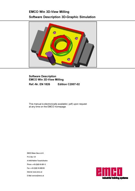
EMCO WIN 3D-VIEW MILLINGINSTALLATIONInstallation of Win 3D-ViewSystem requirementsTo ensure proper run of Win 3D-View the followingminimum requirements must be fulfilled:• PC Celeron oder Pentium III433MHz IBM-compatible, 800MHz recommended• 64 MB RAM, 128 MB RAM recommended• At least 8MB VGA colour graphics card• CD-ROM drive• MF2 keyboard• 5 MB free hard disk memory• WINDOWS 95/98/ME/2000 service pack2/XP• Installation of one of the following WinNC controltypesNote:The following software versions - as indicatedor higher - are necessary for the installation ofthe Win 3D-View:• FAGOR 8055: at least version 1.11• FANUC 0: at least version 14.00• FANUC 21: at least version 14.00• HEIDENHAIN TNC 426: at least version1.30• SINUMERIK 810/820: at least version14.00• SINUMERIK 810D/840D: at least version16.00Variants of Win 3D-ViewEMCO Win 3D-View can be installed for the followingWinNC control types:• FAGOR 8055 TURN and MILL• FANUC 0 TURN and MILL• FANUC 21 TURN and MILL• SINUMERIK 810/820 TURN and MILL• SINUMERIK 810D/840D TURN and MILL• HEIDENHAIN TNC 426 MILLThe following Win 3D-View licences are available:• Demo licence:A demo licence is valid for 30 days from thefirst application. Optionally, this period can beprolonged up to 90 days altogether. Before expiryof the demo licence you may enter a validlicence key (see licence manager on the nextpage).• Programming place:The programming and operation of the respectiveCNC-control type is simulated by WinNC on thePC. The graphic presentation is made possibleby Win 3D-View.• Single licence version:authorizes to use one product copy.• Multiple licence version:authorizes the simultaneous use of as manyproduct copies as desired.• School licence:The school licence is a temporally limitedmultiple licence and only available for a choiceof products.Software installation• Start Windows 95/98/ME/2000/XP.• Insert the CD ROM into the drive.• The installation program is started (CDStart.exe).• You will be guided through the installation by themenu. Just follow the single steps one after theother.5
EMCO WIN 3D-VIEW MILLINGINSTALLATIONLicence inputInput window license key enquiryAfter having been successfully installed, an inputwindow appears during initial operation of an EMCOsoftware product and asks for name, address andlicence key. This input window appears for everysoftware product installed. In case a demo licence isdesired (see page Z1), please select "DEMO".The input window reappears only 5 days before theexpiry of the demo licence. A subsequent input of alicence key is also possible via the licence manager(see licence manager below).License managerFor the release of additional function groups of existingEMCO software products it is necessary to enter anew licence key (exception: demo licence).The EMCO License Manager (see picture on theleft) enables the input of further new license keys. Forthis purpose select the new product in the selectionwindow and confirm the input.EMCO License ManagerThe next time you start your control software an inputwindow appears and asks you to enter name, addressand licence key (see picture on the top left).Please note that the licence key is asked for eachsoftware product individually. The picture on the leftshows e.g. the input prompt for the licence key for thesoftware product "Heidenhain TNC 426".6
EMCO WIN 3D-VIEW MILLINGCALL-UP OF WIN 3D-VIEWCall-up of Win 3D-ViewCall-up in WinNCFAGOR 8055 MC• Press the 3352* key in order to call the directory ofthe stored workpiece programs.Note:Please also refer to "Graphic simulation" that isexplained in detail in the software descriptionFAGOR 8055 MC, chapter C, operation.• Use the cursor to select the workpiece programfrom the left column and the operating cycle, fromwhich the simulation of the part program shall bestarted, from the right column (see picture below).• Press the *5$3+,&6 key.7
EMCO WIN 3D-VIEW MILLINGCALL-UP OF WIN 3D-VIEWCall-up in WinNC FANUC 0-MC• Select the part program desired.Calling up the program on the PC:• Press ).• Enlarge the softkey row by means of ).• Press the "GRAPH" softkey.• Enlarge the softkey row by means of).• Press the "3DVIEW" softkey.Calling up the program by means of thecontrol keyboard:• Press the $8;*5$3+key.• Enlarge the softkey row by pressing .• Press the "3DVIEW" softkey.8
EMCO WIN 3D-VIEW MILLINGCALL-UP OF WIN 3D-VIEWCall-up in WinNC FANUC 21 MB• Select the part program desired.Calling up the program on the PC:• Press ).• Enlarge the softkey row by means of ).• Press the softkey "GRAPH".• Enlarge the softkey row by means of ).• Press the softkey "3DVIEW".Calling up the program by means of thecontrol keyboard:• Press the *5$3+ key.• Enlarge the softkey row by pressing .• Press the "3DVIEW" softkey.9
EMCO WIN 3D-VIEW MILLINGCALL-UP OF WIN 3D-VIEWCall-up in WinNC SINUMERIK 810/820 M• Press the softkey "PART-PROGRAM".• Press the softkey "EDIT".• Enter the program number (e.g. %33) and pressthe softkey "SELECT PROGRAM".The selected part program is displayed.• Press the softkey "3DVIEW".10
EMCO WIN 3D-VIEW MILLINGCALL-UP OF WIN 3D-VIEWCall up in WinNCSINUMERIK 810D/840D• PROGRAM operating mode• Select the desired part program.• Press the softkey "3D-View".11
EMCO WIN 3D-VIEW MILLINGBASIC SETTINGSPress the softkey "TYPE OFGRAPHICS" and select thegraphics type "3D".Basic SettingsInput of the Basic Settings for FAGOR 8055 MCwithout activated 4 th axisPressand select"3D-VIEW PARAMETER".You may define the followingsettings:3D-View View modeGlobal resolution:You may select values between0.01 and 0.3. The higher theresolution, the exacter is thestructure of the 3D-picture.Line of vision:The "line of vision" enables apresetting of the initial view onthe blank workpiece. Of course,the line of vision can always bechanged during simulation bymeans of the mouse.View mode:• Normal presentation• Wire frame complete • Wire frame• Transparent raw part13
EMCO WIN 3D-VIEW MILLINGBASIC SETTINGS3D-View parameter• Fixturevisible/invisibleClamping device position in X- or Y-direction (seechapter Clamping Device Position)• Tailstockvisible/invisible• Toolsvisible/invisible• Collision detectionon/off• Wait states0-99Collision detectionThe collision detection supervises the followingsituations:• Collisions of tool and clamping device. When thedisplay of the clamping device is switched off,collsions of clamping devices are not monitored.• Collisions of non-cutting tool parts with theworkpiece or the clamping device.In case of a collision the simulation will be aborted.Wait statesThe simulation can be slowed down by means ofwaiting cycles. A waiting cycle is the freely definableperiod that has to go by between two tool movements.The waiting cycle is defined in values between 0 and99.The higher the value of the waiting cycle, the longeris the duration of the simulation.14
EMCO WIN 3D-VIEW MILLINGBASIC SETTINGSInput of the Basic Settings for FANUC 0-MC, FANUC 21 MB andSINUMERIK 810/820 MYou may define the following settings:Resolution:You may choose between three resolution settings:0 low1 medium2 highBasic settings for FANUC 0-MCWait states:The simulation can be slowed down by means ofwaiting cycles. A waiting cycle is the freely definableperiod that has to go by between two tool movements.The waiting cycle is defined in values between 0 and99.The higher the value of the waiting cycle, the longeris the duration of the simulation.Tool presentation:visible 1 / invisible 0Collision detection:0 OFF / 1 ONThe collision detection supervises the followingsituations:• Collisions of tool and clamping device. When thedisplay of the clamping device is switched off,collsions of clamping devices are not monitored.• Collisions of non-cutting tool parts with theworkpiece or the clamping device.In case of a collision the simulation will be aborted.Basic settings for FANUC 21 MBClamping Device:0 display of clamping device - OFF1 <strong>manual</strong> clamping device - ON3 automatic clamping device - ONBasic settings for SINUMERIK 810/820 M15
EMCO WIN 3D-VIEW MILLINGBASIC SETTINGSView mode:0 Normal presentation1 Wire frame complete2 Wire frame3 Transparent raw part• Normal presentation• Wire frame complete• Transparent raw part• Wire frameUsage of 4.Axis:0 4 th axis deactivated1 4 th axis activated• Normal presentation• Wire frame complete • Wire frameNotice:With activated 4 th axis the workpiece is shown asa tourning workpiece.• Transparent raw part16
EMCO WIN 3D-VIEW MILLINGBASIC SETTINGSPress the softkey "View".Input of the Basic Settings for SINUMERIK 810D/840Dwithout activated 4 th axisYou may define the followingsettings:Global resolution:You may select values between0.01 and 0.3. The higher theresolution, the exacter is thestructure of the 3D-picture.Line of vision:The "Line of vision" enables apresetting of the initial view onthe blank workpiece. However,the line of vision can always bechanged during simulation bymeans of the mouse.By pressing the softkey "standardview dir." the original view appearsagain.View mode:• Normal presentation• Wire frame complete • Wire framesectional view (related to WCS):The sectional view enables the observation of normallyhidden sequences.The position of the cut surface is defined by inputof coordinates.To display the sectional view, thesimulation has to be started again.• Transparent raw partsectional view17
EMCO WIN 3D-VIEW MILLINGBASIC SETTINGSView:With the section view it is possible to observenormally hidden sequences. You may choosebetween the following views:full 3D-view3/4 view1/2 view1/4 viewPress the "Parameter" softkey.The following inputs are possible:Clamping• Clamping devicevisible/invisible• Clamping device position inX- or Y-direction (see chapterClamping Device Position)General• Collision detection ON/OFF• The dimensions depend onthe machine-coordinatesystemor workpiececoordinate-system.• Tools visible/invisible• Wait states0-99• Actual channel is intendedonly for machines with severalprogramming channels.Collision detectionThe collision detection supervises the following situations:• Collisions of tool and clamping device. When the display of the clampingdevice is not active, collisions of clamping devices are not supervised.• Collisions of non-cutting tool parts with the workpiece or clamping device.In case of a collision the type of collision will be displayed and the simulationwill be aborted.Wait statesThe simulation can be slowed down by means of waiting cycles. A waiting cycleis the freely definable period that has to go by between two tool movements.The waiting cycle is defined in values between 0 and 99.The higher the value of the waiting cycle, the longer is the duration of thesimulation.19
EMCO WIN 3D-VIEW MILLINGBASIC SETTINGSPress the softkey "VIEW".Input of the Basic Settings for HEIDENHAIN TNC 426You may define the followingsettings:Global resolution:You may select values between0.01 bis 0.3. The higher theresolution, the exacter is thestructure of the 3D-picture.Line of vision:The "Line of vision" enables apre-setting of the initial view onthe blank workpiece. However,the line of vision can also bechanged during simulation bymeans of the mouse.By pressing the softkey "standardview dir." the original view appearsagain.View mode:• Normal presentation• Wire frame complete • Wire frame• Transparent raw part20
EMCO WIN 3D-VIEW MILLINGBASIC SETTINGSPress the "PARAMETER"softkey.The following inputs are possible:• Fixturevisible/invisibleSpannmittellage in X- or in Y-direction (see chaptureClamping Device Position)• Tools visible/invisible• Collision detection on/off• Wait states0-99Collision detectionThe collision detection supervises the following situations:• Collisions of tool and clamping device. When the display of theclamping device is not active, collisions of clamping devices are notsupervised.• Collisions of non-cutting tool parts with the workpiece or clampingdevice.In case of a collision the kind of collision will be displayed and thesimulation will be aborted.Wait statesThe simulation can be slowed down by means of waiting cycles. A waitingcycle is the freely definable period that has to go by between two toolmovements.The waiting cycle is defined in values between 0 and 99.The higher the value of the waiting cycle, the longer is the duration of thesimulation.21
EMCO WIN 3D-VIEW MILLINGCLAMPING DEVICE POSITIONClamping Device Positionin the direction of the X-AXISin the direction of the Y-AXIS=
EMCO WIN 3D-VIEW MILLINGSETUP TOOLHOLDERSetup ToolholderInput for Win 3D-View with FAGOR 8055 MCPress"TOOLS".and selectThe left half of the screen showsthe tool stations at the machine.Tool stations that are not occupiedare marked "--EMPTY--" .The right half of the screen showsthe list of available tool types.The lower part of the screenshows the selection boxes for thetool colour.Tool selection FAGOR 8055 MCFor the simulation it is necessary that the correcttools are related to the toolholder positions, just asthe tools must be clamped in the correct toolholderpositions during machining.Win 3D-View offers a tool library that includes allstandard tools of the EMCO PC machines and theEMCO Concept machines.Assign tool to tool station• Select the tool station to which the tool should beassigned by means of the direction keys.• Press ^ to get from the tool stations to the tooltypes. At the selected tool station the text becomesred.• Move to the tool that should be taken over into thetool holder by using the direction keys.• Press the softkey "TAKE TOOL" or (17(5 .• The desired tool will be assigned to the selectedtool station.A possibly already existing tool will be replaced bythe new tool.Remove tool from tool station• Use the direction keys to move the highlight to thetool station from which the tool should be removed.• Press the soft key "REMOVE TOOL".• The tool will be removed and the selected toolstation displays "--EMPTY--".• In this way please enter all tools being necessaryfor the simulation of the respective CNC-programat the corresponding positions.(6&• The changes are activated with the key.• The new settings become only active after thesimulation has been started anew by means ofthe softkeys "CLEAR SCREEN"+"START".Changing the tool colourEvery tool is being assigned a characteristic colourthat is displayed in the right colour field.• Select the tool at the tool station by using thedirection keys.• Press the softkey "CHANGE COLOUR". The toolcolours can be changed as desired by selectingthe RGB-values (red, green, blue) within a rangeof 0 to 255. The selected colour is displayed in theleft colour field.(6&• To save the new colour, please press thekey.• To restore the original colour of a tool, pleasepress the softkey "RESET COLOUR".• You can restore the original colour of all tools bypressing the softkey "STANDARD COLOURS".23
EMCO WIN 3D-VIEW MILLINGSETUP TOOLHOLDERInput for Win 3D-View with FANUC 0-MC, FANUC 21 MB andSINUMERIK 810/820 MFor the simulation the correct tools have to be assignedto the tool positions. The same applies to themachining process, where the tools have to beclamped in the right position on the tool holder.The Win 3D-View offers a tool library that includes allstandard tools of the EMCO PC machines and theEMCO Concept machines.Tool selection FANUC 0-MC• Press the softkey "TOOLS", respectively the softkey "TOOL-SELECT" and the input pictures asshown on the opposite page are displayed.• You can define the tool station in the upper fieldcalled "TOOLHOLDER" by means of the softkeys"POS.+" and "POS.-" or the direction keys.• Select the corresponding tool within the box "TOOLLIBRARY" by using the soft keys "TOOL+" and"TOOL-" or the direction keys.The description and data of the selected tool aredisplayed.• Press the softkey "TAKE OVER", respectively"TAKE" or the ENTER key to assign the selectedtool to the tool station.• In this way enter all tools being necessary for thesimulation of the respective CNC-program in thecorresponding positions.Tool selection FANUC 21 MBNote:The tool number can be entered directly forthe tool holder position, where the cursorstands (e.g. 31 ENTER).Tool selection SINUMERIK 810/820 M24
EMCO WIN 3D-VIEW MILLINGSETUP TOOLHOLDERInput for Win 3D-View with SINUMERIK 810D/840DPress the "Tool" softkey.The left part of the screen showsthe tool stations of the machine.Tool stations that are not occupiedare marked "--EMPTY--".The right part of the screen showsa list of existing tool types.The lower part of the screenshows the selection fields for thetool colour.Tool selection SINUMERIK 810D/840DFor the simulation it is necessary that the correcttools are related to the tool holder positions, just asthe tools must be clamped in the correct toolholderpositions during machining.Win 3D-View offers a tool library that includes allstandard tools of EMCO PC machines and EMCOConcept machines.Assing tool to tool station• Click on the tool that should be taken over into thetool holder.• Click on the tool station to which the selected toolshould be assigned.• Press the "Take tool" softkey.• The desired tool will be assigned to the selectedtool station.A possibly already existing tool will be replaced bythe new one.Remove tool from tool station• Click on the tool station from which the tool shouldbe removed.• Press the "Remove tool" softkey.• The tool will be removed and the selected toolstation displays "--EMPTY--".• In this way please enter all tools, that are necessaryfor the simulation of the corresponding CNCprogram,at the correct tool positions.• By pressing the "OK" softkey the changes areactivated, by pressing "Abort" the changes will bedropped.• The new settings will be only activated after thesimulation has been started again with the "Start"softkey.Change of tool colourEvery tool is being assigned a characteristic colour.In order to change a tool colour you have to select thetool at the tool station by using the direction keys:• Select the tool at the tool station by means of thedirection keys.• Change the tool colours as desired by selectingthe RGB-values (red, green, blue) within a rangeof 0 to 255.• In order to store the new colour please press the"Assign tool colour" softkey.• In order to go back to the original colour of a tool,press the "Reset tool colour" softkey.• You can restore the original colour of all tools bypressing the softkey "Standard tool colours".25
EMCO WIN 3D-VIEW MILLINGSETUP TOOLHOLDERInput for Win 3D-View with HEIDENHAIN TNC 426Press the "TOOLS" softkey.The left part of the scrren showsthe tool stations of the machine.Tool stations that are not occupiedare marked"--EMPTY--".The right part of the screen showsa list of existing tool types.Tool selection HEIDENHAIN TNC 426For the simulation it is necessary that the correcttools are related to the tool holder positions, just asthe tools must be clamped in the correct toolholderpositions during machining.Win 3D-View offers a tool library that includes allstandard tools of EMCO PC machines and EMCOConcept machines.Assign tool to tool station• Use the direction keys to move to the tool stationthat is going to be occupied.• Use this key to change from the tool stationsto the tool types. The text at the chosen toolstation turns blue.• Use the direction keys to move to the tool that isto be taken over into the tool holder.• Press the "TAKE TOOL" softkey or (17 .• The desired tool will be assigned to the selectedtool station.A possibly already existing tool will be replaced bythe new one.Remove tool from tool station• Move the highlight to the tool station, from whichthe tool should be removed, by means of thedirection keys.• Press the "REMOVE TOOL" softkey.• The tool is removed and the selected tool stationdisplays "--EMPTY--".• In this way please enter all tools, that are necessaryfor the simulation of the corresponding CNCprogram,at the correct tool positions.• By pressing the "END" softkey the changes areactivated.• The new settings will be only activated after thesimulation has been started again with the"RESET+START" softkey.Change of tool colourEvery tool is being assigned a characteristic colour.The specific tool colour is shown in the right colourfield.• Select the tool at the tool station by means of thedirection keys.• Press the"CHANGE TOOL COLOURS" softkey.Change the tool colours as desired by selectingthe RGB-values (red, green, blue) within a rangeof 0 to 255. The chosen colour is displayed in theleft colour field.• In order to store the new colour, please press the"END" softkey.• In order to go back to the original colour of a tool,press the "RESET TOOL COLOURS" softkey.• You can restore the original colour of all tools bypressing the softkey "STANDARD TOOLCOLOURS".26
EMCO WIN 3D-VIEW MILLINGDEFINE WORKPIECEDefine WorkpieceDefine blank workpiece for FAGOR 8055 MCwithout activated 4 th axisIt is possible to change the size ofthe display before the simulationstarts. The display size can bedefined anew by setting newmaximum and minimum valuesfor the axis. The values arereferred to the machine datum.• Press the softkey "DISPLAYAREA".• Select the individual fields withthe direction keys@andInput picture for blank workpiece definition>and enter thecorresponding value.• Confirm the input with (17(5 .If you wish to leave the modewithout any changes, press(6&.(X MIN/Y MAX/Z MAX)(X MAX/Y MAX/Z MAX)CLAMPSDistance between the upper sideof the collets and the upper sideof the workpiece.CLAMPS(X MIN/Y MIN/Z MIN)ZYX27
EMCO WIN 3D-VIEW MILLINGDEFINE WORKPIECEDefine blank workpiece for FANUC 0-MC, FANUC 21 MB andSINUMERIK 810/820 M without activated 4 th axisBlank workpiece definition FANUC 0-MC• Press the softkey "WORKP.", respectively"WORK-PIECE".• Use the direction keys to select the individualvalues.Below the display of the blank workpieces theSINUMERIK 810/820 M displays the meaning ofthe respective value (e.g. WORKPIECE-REF.PT. (Z)).• You have to enter the following data:Position of the workpiece datum in relation tothe machine datum M in X, Y and Z.Dimension of the blank workpiece in relation tothe workpiece datum W in +X, -X, +Y, -Y, +Z and-Z.Protruding length of the blank workpiece fromthe clamping device in Y and Z respectively X andZ (the clamping device can be rotated by 90° - seeClamping Device Position).• The arrows in the input mask indicate the positivedirection of the corresponding input value. Theindividual values can be either positive or negative(except expansion in Z) which leads to differentsituations of the blank workpieces (please refer toexamples of blank workpiece definitions).Blank workpiece definition FANUC 21 MBNote:The simulation also considers the zero offsetsthat are called up in the programm with G54 -G59. Therefore, they have to be taken intoconsideration when defining the positions ofthe blank workpieces.Blank workpiece definition SINUMERIK 810/820 M28
EMCO WIN 3D-VIEW MILLINGDEFINE WORKPIECEDefine blank workpiece for FANUC 21 MB andSINUMERIK 810/820 M with activated 4 th axisBlank workpiece definition FANUC 21 MB• Press the softkey "WORKP.", respectively"WORK-PIECE".• Use the direction keys to select the individualvalues.Below the display of the blank workpieces theSINUMERIK 810/820 M displays the meaning ofthe respective value (e.g. WORKPIECE-REF.PT. (Z)).• You have to enter the following data:Position of the workpiece datum in relation tothe machine datum M in X, Y and Z.Dimension of the blank workpiece in relation tothe workpiece datum W in +X and -X.Diameter of the blank workpieceProtruding length of the blank workpiece fromthe clamping device in X.• The arrows in the input mask indicate the positivedirection of the corresponding input value. Theindividual values can be either positive or negative(except for the diameter) which leads to differentsituations of the blank workpieces (pleaserefer to examples of blank workpiece definitions).Blank workpiece definition SINUMERIK 810/820 MNote:The simulation also considers the zero offsetsthat are called up in the programm with G54 -G59. Therefore, they have to be taken intoconsideration when defining the positions ofthe blank workpieces.29
EMCO WIN 3D-VIEW MILLINGDEFINE WORKPIECEDefine blank workpiece for SINUMERIK 810D/840Dwithout activated 4 th axisInput picture for blank workpiece definition• Press the "Workpiece" softkey.• You may select every single value by using the mouse or the directionkeys• The following dimensions have to be entered:Position of the workpiece datum related to the machine datum Min X, Y and Z.Expansion of the blank workpiece related to the workpiece datumW in -X, +X, -Y, +Y, -Z and +Z.Projecting length of the blank workpiece from the clampingdevice.• Confirm the entry with "OK".Notice:The simulation also considersthe zero offsets that are calledup in the program by G54-G59 and therefore must betaken into account during thedefinition of the workpieceposition.30
EMCO WIN 3D-VIEW MILLINGDEFINE WORKPIECEDefine blank workpiece for SINUMERIK 810D/840Dwith activated 4 th axisInput picture blank workpiece definition• Press the "Workpiece" softkey.• You may select every single value by using the mouse or the directionkeys.• The following dimensions have to be entered:Position of the workpiece datum related to the machine datum Min X, Y and Z.Expansion of blank workpiece related to the workpiece datum W in+X and -X.Diameter of the blank workpiece.Projecting length of the blank workpiece from the clamping devicein X.• Confirm the entry by pressing "OK".Notice:With activated 4 th axis theworkpiece is shown as atourning workpiece.The simulation also considersthe zero offsets that are calledup in the program by G54-G59 and therefore must betaken into account during thedefinition of the workpieceposition.31
EMCO WIN 3D-VIEW MILLINGDEFINE WORKPIECEDefine blank workpiece for HEIDENHAIN TNC 426Input picture for blank workpiece definition• Press the "RAW PART" softkey.• You may select single values by using the direction keys.• The following dimensions have to be entered:Position of the workpiece datum related to the machine datum Min X, Y and Z.Projecting length of the blank workpiece from the clampingdevice.• Confirm the entry by pressing "END".Notice:Please also consider thedetailed description of theworkpiece definition in thesoftware descriptionHEIDENHAIN TNC 426(chapter C Operation: defineblank form)32
EMCO WIN 3D-VIEW MILLINGDEFINE WORKPIECEExamples for Workpiece DefinitionEntry at the screenReal clamping situation and illustration:0=
EMCO WIN 3D-VIEW MILLINGSIMULATIONSimulationSimulation sequence for Win 3D-View with FAGOR 8055 MCAfter having called the simulation,the menu appears.The rectangle in the oppositeillustration is the simulationwindow.In the simulation window themachining of the workpiece isshown.In addition to the simulationwindow the current feeds, spindlespeeds, names and positionvalues of the tool as well as thecurrent cycle are displayed.Error messages also appearhere. E.g. danger of collision.Simulation window FAGOR 8055 MCSoftkey "START"The simulation is started with "START". Before beingable to start the simulation, a CNC program musthave been selected.Softkey "STOP"The simulation is interrupted with "STOP". To continuethe simulation, press the softkey "START".Softkey "SBL"The softkey "SBL" enables to stop the simulationafter every block. The simulation can be continued bypressing the soft key "START".Softkey "CLEAR SCREEN"With "CLEAR SCREEN" both the simulation and theCNC program return to their starting position (firstprogram block).Display mode, section viewThe softkey "3D-VIEW PARAMETER" (see BasicSettings) enables the setting of the display mode.Rotate picture, zoom, shiftThe simulation window can be rotated as desiredwithin one plane and at any time by pressing andholding the left mouse key. For movements aroundthe Z-axis you have to press6KLIW+ left mouse key+ mouse movement to the right or to the left.The simulation window can be enlarged or reducedby means of the softkeys "ZOOM+" and "ZOOM-" orby means of &WUO+ left mouse key + upward ordownward mouse movement.The direction keys enable to shift the simulationwindow.Press the right mouse button + mouse movement inthe required direction to shift the simulation image inan infinitely variable way.The original line of vision is restored with the softkey"RESET LINE OF VISION".34
EMCO WIN 3D-VIEW MILLINGSIMULATIONSimulation sequence for Win 3D-View with FANUC 0-MC, FANUC 21 MBand SINUMERIK 810/820 M• Press the softkey "SIMULATION" , respectively"SIMUL.".The rectangle in the picture is the simulation window.In the simulation window the machining of theworkpiece is shown.In addition to the simulation window the currentposition values of the tool and the current programblock are displayed.The WinNC SINUMERIK 810/820 M additionallyshows the current subprogram and the feed.Simulation window FANUC 0-MCSimulation window FANUC 21 MBThe following softkeys are at your disposal:"SECTION", "START", "STOP" and "RESET".The function of the softkeys "BLOCK SEARCH" and"PROGRAM CONTROL" is the same as for WinNCwithout 3D-View.Softkey "START"The simulation is started with "START". Before beingable to start the simulation, a CNC program musthave been selected.Softkey "STOP"The simulation is interrupted with "STOP". To continuethe simulation, press the softkey "START".Softkey "RESET"With "RESET" both the simulation and the CNCprogram return to their starting position (first programblock).Rotate picture, zoom, shiftThe simulation window can be rotated as desiredwithin one plane and at any time by pressing andholding the left mouse key. For movements aroundthe Z-axis you have to press6KLIW+ left mouse key+ mouse movement to the right or to the left.The simulation window can be enlarged or reducedby means of the softkeys "ZOOM+" and "ZOOM-" orby means of &WUO+ left mouse key + upward ordownward mouse movement.The direction keys enable to shift the simulationwindow.Press the right mouse button + mouse movement inthe required direction to shift the simulation image inan infinitely variable way.Simulation window SINUMERIK 810/820 M35
EMCO WIN 3D-VIEW MILLINGSIMULATIONSimulation sequence for Win 3D-View with SINUMERIK 810D/840DPress the "3D-View" softkey.The rectangle in the picture onthe left is the simulation window.The machining of the workpieceis shown in the simulation window.In addition to the simulationwindow the actual feeds, spindlespeeds, names and positions ofthe tool, machining time as wellas the current program block aredisplayed.Error messages also appearhere, e.g. danger of collision.Simulation window SINUMERIK 810D/840DSoftkey "Start"With "Start" the simulation is started. Before beingable to start a simulation, a CNC program must havebeen selected . The name of the actual CNC programis displayed in the upper center of the simulationwindow, e.g. DEMO100.MPF.Softkey "Single"With the "Single" softkey the simulation is stoppedafter every block. The simulation can be continued bypressing the "Start" softkey.Softkey "Reset"With "Reset" both the simulation and the CNC programare set back to the inital status (first programblock).Display mode, selection viewThe softkey "View" enables the setting of the displaymode and of the section view (see Basic Settings).After having finished the simulation it is possible tochange the display mode by means of the softkeys"Wire frame" and "Solid view". During a simulationrun the display mode can only be changed by pressing"Single" before and after the new selection.Rotate picture, Zoom, ShiftThe simulation picture can be rotated as desiredwithin one plane and at any time by pressing andholding the left mouse key. For movements aroundthe Z-axis you have to press6KLIW+ left mouse key+ mouse movement to the right or to the left.The simulation window can be enlarged or reducedby means of the softkeys "Zoom+" und "Zoom-" or by&WUOmeans of + left mouse key + upward ordownward mouse movement.The direction keys enable to shift the simulationwindow.Press the right mouse button + mouse movement inthe required direction to shift the simulation image inan infinitely variable way.Save active partThe "Save/clear active part" softkey saves thecurrently machined workpiece. It can be used againafter "Reset", during a new start. The selection canbe cancelled by pressing the softkey again.36
EMCO WIN 3D-VIEW MILLINGSIMULATIONSimulation sequence for Win 3D-View with HEIDENHAIN TNC 426Press this softkey: .Select one of the screen layouts,"PROGRAM+GRAPHICS" or"GRAPHICS", viaor. The section is thesimulation window.The machining of the workpieceis shown in the simulation window.In addition to the simulationwindow the machining time isdisplayed at the bottom right.Simulation window HEIDENHAIN TNC 426Softkey "START"With "START" the simulation is started. Before beingable to start a simulation, a CNC program must havebeen selected.Softkey "START SINGLE"With the "START SINGLE" softkey the simulation isstopped after every block. The simulation can becontinued by pressing the key again.Softkey "RESET+START"With "RESET+START" both the simulation and theCNC program are set back to the inital status (firstprogram block) and a new simulation is started.Illustration mode, Cross sectionThe softkey "View" enables the setting of theillustration mode (see Basic Settings).Rotate picture, Zoom, ShiftThe simulation picture can be rotated as desiredwithin one plane and at any time by pressing andholding the left mouse key. For movements arountthe Z-axis you have to press6KLIW+ left mouse key+ mouse movement to the right or to the left.The simulation window can be enlarged or reducedby means of the softkeys "Zoom+" und "Zoom-" or by&WUOmeans of + left mouse key + upward ordownward mouse movement.The softkeys that symbolize arrows enable to shiftthe simulation picture.Press the right mouse button + mouse movement inthe required direction to shift the simulation image inan infinitely variable way.You can go back to the original initial view by pressingthe softkey "STANDARD LINE OF VISION".Machining timeThe machining time is the approximate time that theWinNC calculates for the duration of the toolmovements, that are carried out with feed. Thiscalculated time cannot be used for the calculation ofthe production time, since the WinNC does notconsider periods that depend on the machine type(e.g. for tool change).Machining times can be stored, added or deleted.37
EMCO WIN 3D-VIEW MILLING38
EMCO WIN 3D-VIEW MILLING3D-TOOLGENERATOR##Werkzeugmodellierung_mit_3D-ToolGenerator##Tool modelling with the 3D-Tool GeneratorWith the 3D-ToolGenerator you can modify existingtools and create new tools.1 Register cards for "Geometry", "General" and"Machines" for drilling and <strong>milling</strong> tools and"Tip", "Holder", "General" and "Machines" forturning tools.2 Selection of tool types3 This window enables the input of tool dimensions.4 Graphical support for the tool dimensioning5 Choice of tools for the selected tool type6 Choice of tool types (here: only drill)"Turning tool", "Milling tool" and "Drilling tool"reduce the tool choice to the respective type(here: only drilling tools are listed)."All" does not reduce the tool choice.7 Buttons for quickly browsing through the toolsgo to first tool in the groupgo to last tool in the groupgo forward in the list by one toolgo back in the list by one tool8 Button to delete tools9 Button to create new tools10 Button to copy tools11 Button to save changes12 Button for 3D visualization13 Button to sort tools14 Button to terminate the <strong>3DView</strong> tool generator39
EMCO WIN 3D-VIEW MILLING3D-TOOLGENERATORGenerating a new tool• Set the selection for tool types to "Selection all".• Press the button to generate new tools.• Select the tool name, the tool type and themeasurement system.• Confirm the entries with "OK".• Define all tool dimensions.• Define all tool colours (see"select tool colour").• Confirm the entries with "Store".Copying a tool• Call the tool you wish to copy.• Press the button to copy tools.• Enter the new tool name.• Confirm the inputs with "Save".40
EMCO WIN 3D-VIEW MILLING3D-TOOLGENERATORChanging an existing tool• Call the tool you wish to change.• Change the values.• Confirm the entries with "Store".Selecting a tool colour• Make a double click with themouse pointer in the colouredbox of the tool colour. Thewindow "Select tool colour"will appear.• Select the required colour.• Confirm the entries with "OK".Visualizing a tool• Press the button for 3D visualization.Rotating imageAt any time you can rotate the simulation image inone plane as required by pressing and holding the leftmouse button. For movements around the Z axispress + left mouse button + mouse movementto the right or to the left.ZoomingYou can zoom the tool simulation image in or out bymeans of + left mouse button + mousemovement upwards or downwardsShiftingPress the right mouse button + mouse movement inthe required direction to shift the simulation image.41
EMCO WIN 3D-VIEW MILLING3D-TOOLGENERATORSorting functionThe sorting sequence makes it possible to displaythe tools being sorted according to tool types.Every time the sorting sequence is changed, theselection for tools will be updated.• Press the button for sorting.• Define new sorting sequence.• Confirm the entries with "OK".42


