
Create successful ePaper yourself
Turn your PDF publications into a flip-book with our unique Google optimized e-Paper software.
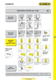
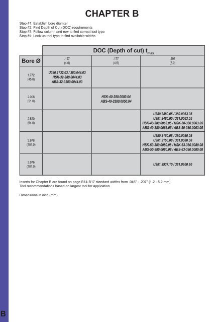
GROOVE MILLING by circular interpolationMILLING SHANK Type380BDepth of groove up toWidth of groove up toCutting edge Ø.157″ (4.0 mm).236″ (6.0 mm)Ds 1.732″ (44.0 mm)for use with IndexableinsertTypeRU314R314Picture = right hand cutting version shownPart number Z Ds t maxl 1d 1d λ380.0044.03A380.0044.03B380.0044.03EFurther sizes upon request3 44 4 125 34 25 14°Dimensions in mmSpare partsMilling shank Screw Torque TORX PLUS® Wrench380.0044.03... 5.12T20P 53 - 58 lbf-in. T20PQIn the UNITED STATES cal us toll free1 - 888 - 818 HORNB3
GROOVE MILLING by circular interpolationBMILLING CUTTER TypeU380Depth of groove up toWidth of grooveCutting edge Ø.197″.236″Ds 2.480″for use with IndexableinsertTypeRU314R314Picture = right hand cutting version shownPart number Z Ds h h 2d 2t maxλU380.2480.05 5 2.480 1.575 1.559 2.008 .197 10°Further sizes upon requestDimensions in inchSpare partsMilling Cutter Screw Screw Torque TORX PLUS® Wrench WasherU380.2480.05 10.25.912 5.12T20P 53 - 58 lbf-in. T20PQ 10.5.433B4In the UNITED STATES cal us toll free1 - 888 - 818 HORN
GROOVE MILLING by circular interpolationMILLING CUTTER Type380BDepth of groove up toWidth of groove up toCutting edge Ø.197″ (5.0 mm).236″ (6.0 mm)Ds 2.480″ (63.0 mm)Cutterhole and cross keyway as per DIN 138for use with IndexableinsertTypeRU314R314Picture = right hand cutting version shownPart number Z Ds h h 2d 2t maxλ380.0063.05 5 63 40 39.6 51 5 10°Further sizes upon requestDimensions in mmSpare partsMilling Cutter Screw Screw Torque TORX PLUS® Wrench Washer380.0063.05 10.25.912 5.12T20P 53 - 58 lbf-in. T20PQ 10.5.433In the UNITED STATES cal us toll free1 - 888 - 818 HORNB5
GROOVE MILLING by circular interpolationBMILLING CUTTER TypeU380Depth of groove up toWidth of grooveCutting edge Ø.197″.236″Ds 3.150″Cutterhole and cross keyway as per DIN 138for use with IndexableinsertTypeRU314R314Picture = right hand cutting version shownPart number Z Ds h h 2d 2t maxλU380.3150.08 8 3.150 1.260 1.244 2.677 .197 10°Further sizes upon requestDimensions in inchSpare partsMilling Cutter Screw Torque TORX PLUS® WrenchU380.3150.08 5.12T20P 53 - 58 lbf-in. T20PQB8In the UNITED STATES cal us toll free1 - 888 - 818 HORN
GROOVE MILLING by circular interpolationMILLING CUTTER Type380BDepth of groove up toWidth of groove up toCutting edge Ø.197″ (5.0 mm).236″ (6.0 mm)Ds 3.150″ (80.0 mm)Cutterhole and cross keyway as per DIN 138for use with IndexableinsertTypeRU314R314Picture = right hand cutting version shownPart number Z Ds h h 2d 2t maxλ380.0080.08 8 80 32 31.6 68 5 10°Further sizes upon requestDimensions in mmSpare partsMilling Cutter Screw Torque TORX PLUS® Wrench380.0080.08 5.12T20P 53 - 58 lbf-in. T20PQIn the UNITED STATES cal us toll free1 - 888 - 818 HORNB9
GROOVE MILLING by circular interpolationBMILLING CUTTER TypeHSK..380with through coolantDepth of groove up toWidth of groove up toCutting edge Ø from.197″ (5.0 mm).236″ (6.0 mm)Ds 1.732″ (44.0 mm)for use with IndexableinsertTypeRU314R314Picture = right hand cutting version shownHSK-coupling systemPart number Z Ds h d 2t maxλHSK-32-380.0044.03 3 44 55 34 4.0 14°HSK-40-380.0050.04 4 50 55 40 4.5 14°HSK-40-380.0063.05 5 63 55 51 5.0 10°HSK-50-380.0063.05 5 63 65 51 5.0 10°HSK-50-380.0080.08 8 80 65 68 5.0 10°HSK-63-380.0080.08 8 80 70 68 5.0 10°Further sizes upon requestDimensions in mmSpare partsMilling Cutter Screw Torque TORX PLUS® WrenchHSK-... 5.12T20P 53 - 58 lbf-in. T20PQB10In the UNITED STATES cal us toll free1 - 888 - 818 HORN
GROOVE MILLING by circular interpolationMILLING CUTTER TypeABS..380with through coolantBDepth of groove up toWidth of groove up toCutting edge Ø from.197″ (5.0 mm).236″ (6.0 mm)Ds 1.732″ (44.0 mm)for use with IndexableinsertTypeRU314R314Picture = right hand cutting version shownABS-coupling systemlicence KOMETPart number Z Ds h d 2t maxλABS-32-380.0044.03 3 44 35 34 4.0 14°ABS-40-380.0050.04 4 50 40 40 4.5 14°ABS-40-380.0063.05 5 63 40 51 5.0 10°ABS-50-380.0063.05 5 63 50 51 5.0 10°ABS-50-380.0080.08 8 80 50 68 5.0 10°ABS-63-380.0080.08 8 80 63 68 5.0 10°Further sizes upon requestDimensions in mmSpare partsMilling Cutter Screw Torque TORX PLUS® Wrench ABS setABS-32-380.0044.03 5.12T20P 53 - 58 lbf-in. T20PQ ABS-32-ES-M3ABS-40-380.00...04/05 5.12T20P 53 - 58 lbf-in. T20PQ ABS-40-ES-M3ABS-50-380.00...05/08 5.12T20P 53 - 58 lbf-in. T20PQ ABS-50-ES-M3ABS-63-380.0080.08 5.12T20P 53 - 58 lbf-in. T20PQ ABS-63-ES-M3In the UNITED STATES cal us toll free1 - 888 - 818 HORNB11
GROOVE MILLING by circular interpolationBDISC MILLING CUTTER TypeU381Depth of groove up toWidth of groove up toCutting edge Ø.197″.236″Ds 2.480 - 3.937″Bore (d 2) with longitudinal keyway to DIN 138for use with IndexableinsertTypeRU314R314R = right hand cutting - left side mountedL = left hand cutting - right side mountedPart number Z Ds h h 2d 3d 2dkλ t maxR/LU381.2480.05 5 2.480 .551 .559 1.220 .750 2.008 14° .197R/LU381.3150.08 8 3.150 .630 .638 1.693 1.000 2.677 10° .197R/LU381.3937.10 10 3.937 .787 .795 1.890 1.250 3.465 10° .197Further sizes upon requestDimensions in inchSpare partsDisc milling cutter Screw Torque TORX PLUS® WrenchR/LU381.... 5.12T20P 53 - 58 lbf-in. T20PQB12In the UNITED STATES cal us toll free1 - 888 - 818 HORN
GROOVE MILLING by circular interpolationDISC MILLING CUTTER Type381BDepth of groove up toWidth of groove up toCutting edge Ø.197″ (5.0 mm).236″ (6.0 mm)Ds 2.480″ (63.0 mm)Bore (d 2) with longitudinal keyway to DIN 138for use with IndexableinsertTypeRU314R314R = right hand cutting - left side mountedL = left hand cutting - right side mountedPart number Z Ds h h 2d 3d 2dkλ t maxR/L381.0063.05 5 63 14 14.2 34 22 51 14° 5R/L381.0080.08 8 80 16 16.2 43 27 68 10° 5R/L381.0100.10 10 100 20 20.2 48 32 88 10° 5State R or L versionDimensions in mmFurther sizes upon requestSpare partsDisc milling cutter Screw Torque TORX PLUS® WrenchR/L381.0... 5.12T20P 53 - 58 lbf-in. T20PQIn the UNITED STATES cal us toll free1 - 888 - 818 HORNB13
GROOVE MILLING by circular interpolationBINDEXABLE INSERT TypeU314Depth of grooveWidth of groove.197″.046 - .187″for use with Milling shankTypeU380 / 380U381 / 381ABS..380HSK..380R = right hand version shownL = left hand versionPart number w r sMG12TN35TI25R/LU314.0046.00 .046 -•/•R/LU314.0062.00 .062 .004 •/•R/LU314.0078.00 .078 .006 •/•R/LU314.0094.00 .094 .006 .213•/•R/LU314.0125.00 .125 .006 •/•R/LU314.0157.00 .157 .006 •/R/LU314.0187.00 .187 .006 •/•Dimensions in inchState R or L version●/+ = on stock / 6 weeksB14In the UNITED STATES cal us toll free1 - 888 - 818 HORN
GROOVE MILLING by circular interpolationINDEXABLE INSERT Type314BDepth of groove up toWidth of groove Nw.197″.051 - .203″Widths for circlip grooves DIN 471/472for use with Milling CutterTypeU380 / 380U381 / 381ABS..380HSK..380R = right hand version shownL = left hand versionPart number Nw w r sMG12TN35TI25TF45R/L314.0130.00 .051 .056 .004•/•R/L314.0160.00 .063 .067 .004 •/•R/L314.0185.00 .073 .077 .006 •/•R/L314.0215.00 .085 .089 .006 •/ •/•.213R/L314.0265.00 .104 .109 .006 •/ •/• •/R/L314.0315.00 .124 .128 .006 •/ •/• •/R/L314.0415.00 .163 .168 .006 •/ •/• •/R/L314.0515.00 .203 .207 .006 •/ •/• •/Dimensions in inchState R or L version●/+ = on stock / 6 weeksIn the UNITED STATES cal us toll free1 - 888 - 818 HORNB15
GROOVE MILLING by circular interpolationBINDEXABLE INSERT Type314machining of aluminiumDepth of groove up toWidth of groove Nw.197″.051 - .203″Widths for circlip grooves DIN 471/472for use with Milling CutterTypeU380 / 380U381 / 381ABS..380HSK..380R = right hand version shownL = left hand versionPart number Nw w r sMG12TN35TI25TF45R/L314.0130.40 .051 .056 .004+/ •/R/L314.0160.40 .063 .067 .004 •/ •/R/L314.0185.40 .073 .077 .006 +/ •/R/L314.0215.40 .085 .089 .006 +/+ •/.213R/L314.0265.40 .104 .109 .006 •/+ •/R/L314.0315.40 .124 .128 .006 •/+ •/R/L314.0415.40 .163 .168 .006 •/ •/R/L314.0515.40 .203 .207 .006 •/+ •/Dimensions in inchState R or L version●/+ = on stock / 6 weeksB16In the UNITED STATES cal us toll free1 - 888 - 818 HORN
GROOVE MILLING by circular interpolationINDEXABLE INSERT Type314BDepth of groove up toWidth of groove Nw.118″.043 - .203″Widths for circlip grooves DIN 471/472 with chamferfor use with Milling CutterTypeU380 / 380U381 / 381ABS..380HSK..380R = right hand version shownL = left hand versionPart number Nw w r t 1s 1s t maxMG12TN35TI25TF45R/L314.1105.54 .043 .048.019 .178.020 +/R/L314.1307.54 .051 .056 .026 .182 .028R/L314.1308.54 .051 .056 .004 .033 .182 .215 .034 +/+R/L314.1609.54 .063 .067 .033 .178 .034 •/+R/L314.1610.54 .063 .067 .038 .178 .039 +/•R/L314.1812.54 .073 .077.048 .183.049 •/•R/L314.2115.54 .085 .089 .058 .189 .059 •/•R/L314.2616.54 .104 .109 .058 .179 .059 •/•R/L314.2617.54 .104 .109 .006 .068 .179 .215 .069 •/•R/L314.3118.54 .124 .128 .068 .189 .069 •/•R/L314.4120.54 .163 .168 .078 .196 .079 •/R/L314.4125.54 .163 .168 .097 .196 .098 •/+R/L314.5130.61 .203 .207 .006 .117 .230 .240 .118 •/Dimensions in inchState R or L version●/+ = on stock / 6 weeksIn the UNITED STATES cal us toll free1 - 888 - 818 HORNB17
TECHNICAL INFORMATIONFeed rates and time calculationIt is simple and easy to calculate your speed and feedsusing HORN‘S HCT program. We recommend thatyou calculate the cutting data with this program as itwill provide you with the best cutting performance andresults. Basic features of the calculations can be foundon the follwing pages.HCT(HORN Circular Technology)- safe and fast -Your cutting data for groove milling bycircular interpolation of internal andexternal grooves as well as groovemilling of linear grooves.System requirements from Windows 95.Available on CD-ROM.BASIC RECOMMENDATIONSOverhang of the milling cutterSelect the shortest possible clamping device and millingshank, and control the runout tolerance of the tools.Large cutting widths in combination with long overhangsrequire specific manufacturing methods such as dividingthe cutting width to achieve the best possible cuttingresult due to reduced cutting forces.HDiameter of the milling cutterWhen using a large diameter cutter, whose relationshipis close to the bore diameter, manufacturing cycletimecan be reduced, due to the smaller center of rotation andhigher feed rates. Many times the rotation of the millingcutter centre will be defined by the parameters of theworkpiece and the whole application setup.Clamping torque of the screwsWe recommend to use a torque screw driver to achievethe indicated torque values per insert and tool type.Additional additives such as copper paste are notpermitted. This will have a negative effect and changethe clamping forces.All clamping screws are already coated withadditives.M dIn the UNITED STATES call us toll free1 - 888 - 818 HORNH1
TECHNICAL INFORMATIONMilling directionMost HORN milling tools are right handed , and it isrecommended to use them with the climb milling processas this is generally recommend for carbide tools.HMilling entry into the workpieceA simple radial entry of the milling cutter creates a verylong contact angle which leads to vibrations which willnot disappear for the rest of the milling operation and arevisual on the bottom of the groove.It is recommended to enter the groove with a rampangle of 45° up to 180° to the maximum depth of cut.The calculated cutting data refers to the milling conditionwhen the insert is in the full cut but can be also used forthe entry loop.Ramp angle > 45°Bore milling and offset milling by helicalinterpolationHORN milling inserts are manufactured with a round chipbreaker. This means that beyond a depth of cut of 2 mmin axial direction the insert gets a negative cutting angle.Milling inserts are limited to a depth of cut of 2 mm whenused for helical interpolation. Larger depths of cut canonly be produced when choosing special chip breakers.Please contact us in case of any further questions.H2In the UNITED STATES call us toll free1 - 888 - 818 HORN
TECHNICAL INFORMATIONSinlge edged insertsWhen entering through a bore off center and withoutrotating it is possible to generate back chamfers andflats with inserts having a larger cutting diameter thanthe bore diameter. Single edged cutters have no run outtolerance.Thread millingHWith HORN thread milling inserts the thread profile isgenerated in one full cut to the profile depth of the thread.This produces threads with minimal taper especially inhigh alloyed steels.In blind holes it is recommended to mill from the bottomto the top. Otherwise there is the risk of damaging thetool because of milling into chips at the bottom of theblind hole.A general recommendation for thread milling:The milling cutter diameter should not exceed 70% of theminor diameter of the thread. Otherwise recutting of theprofile occurs which could bring the whole thread out oftolerance.In the UNITED STATES call us toll free1 - 888 - 818 HORNH3
CHOICE OF CARBIDE GRADESSynthetic cutting-tool materialPD10PD20Wear resistanceCutting speedToughnessFeed rateCB10CB20HCarbide Gradesuncoated coatedMG12 TI25MG12 TN35 TH350110203040102030N4001102030Non ferrous metal High temp. alloys Hardened materialsSHWear resistanceCutting speedToughnessFeed rate01102030401020304001102030PCarbide GradesMain selection supplementary gradesH35TH35TN35TI25H54 TF45MG12TN35TI25H54TF45MG12TF46Steel Stainless steel Grey cast iron / AluminiumMKH4In the UNITED STATES call us toll free1 - 888 - 818 HORN
GROOVE MILLING by circular interpolationMILLING OF A LINEAR GROOVE - EXTERNALs z= h m√ 2r a rs = n • z • s zmm/minHCos φ° = r2 + [R + r - a r] 2 - R 2 φ°2r [R + r - a r]L = • 2r • φ° mm360°Length of cutt =A Tn • z • A zminTime for cut (for A T)A Z= L • h мmm 2 s' 2= s' 1Area of chips' 1= • 2 (R+r-a r ) mm/mintFeed rate of tool centreA T= [R 2 -(R-a r) 2 ] mm 2Area of groove sectionR - a rR + r - a rmm/minFeed rate of tool tipHCT (HORN Circular Technology)- safe and fast -Your cutting data for groove milling by circular interpolation of internal and external grooves as well as groove millingof linear grooves.System requirements from Windows 95. Available on CD-ROM.In the UNITED STATES call us toll free1 - 888 - 818 HORNH5
GROOVE MILLING by circular interpolationMILLING OF AN INTERNAL GROOVEHCos [180° - φ°] = r2 + [R + a r- r] 2 - R 2 180° - φ° φ°2r [R + a r- r]L = • 2r • φ° mm360°Length of cutt =A Tn • z • A zminTime for cut (for A T)A Z= L • h mmm 2 s' 2= s' 1Area of chips' 1= • 2 (R+r-a r ) mm/mintFeed rate of tool centreA T= [R 2 -(R-a r) 2 ] mm 2Area of groove sectionR - a rR + r - a rmm/minFeed rate of tool tipSpecificationISO Specification Specification ISO SpecificationFeed rateRevolutionsNumber of teethFeed/toothmedium thickness ofchipradial depth of cutr rs'v fRadius of cuttera ra ennRadius of workpieceRRzs zzf zFeed rate of tool centres‘ 1v f 3h mh mFeed rate of tool tips‘ 2v f2H6In the UNITED STATES call us toll free1 - 888 - 818 HORN
Available METRIC size carbide and tungstenalloy shanks - SummaryDimensions in mm Part number Inserts (inch and metric) Use Pagel 1d g6l 2d 1Type t maxDs130 12 40 11 M116.0012.01B130 12 56 11 M116.0012.02B130 16 40 11 M116.0016.01B/E130 16 56 11 M116.0016.02B/E150 16 80 11 M116.0016.03B/E80 12 21 6 M306.0012.01B/E/A90 12 30 6 M306.0012.02B/E/A100 12 42 6 M306.0012.03B/E/A116 4.3 20.4 A53116 4.3 20.4 A53108/306 1.0/2.5 9.6/11.7 A3 - A4100 7.5 - 6 M306.0707.03AD3; E2108/306 0.85/2.0 9.3/11.7120 10 - 6 M306.1010.03A E290 12 30 7.3 M306.0712.02B/E/A100 16 25 7.3 M306.0716.01/B/E/A108/306 0.7/2.0 9.6/11.7 A3 - A4; D360 10 15.2 6 M306.ST10.01A 108/306 1.0/2.5 9.4/11.7 A595 12 29 8 M308.0012.01B/E/A110 12 42 8 M308.0012.02B/E/A120 12 56 8 M308.0012.03B/E/A111/308/608 2.3/3.5 13.4/15.7 A23-A24160 12 - - M308.0012.07A 111/308/608 2.3/3.5 13.4/15.7 D11; E8110 12 42 9.5 M308.1012.02B/E/A110 16 33 9.5 M308.1016.01B/E/A60 10 17.7 8 M308.ST10.01A70 13 25.7 8 M308.ST13.01A100 12 32 9 M311.0012.01B/E/A100 12 45 9 M311.0012.02B/E/A120 12 64 9 M311.0012.03B/E/A111/308 1.5/2.7 13.4/15.7 A23-A24; D11111/308 2.3/3.5 13.4/15.7 A25311/611 3.5/2.5 17.7 A39-A4090 16 25 9 M311.0016.00B/E 311 3.6 17.0 G3100 16 32 9 M311.0016.01B/E/A110 16 45 9 M311.0016.02B/E/A130 16 64 9 M311.0016.03B/E/A110 16 32 13 M311.0016.04B/E/A130 16 45 13 M311.0016.05B/E/A60 10 17.7 9 M311.ST10.01A311/611 3.5/2.5 17.7 A39-A40311/611 1.5 17.7 A39-A40; D2170 13 25.7 9 M311.ST13.01A 311/611 3.5 17.7A4180 16 25.7 9 M311.ST16.01A100 12 - - M313.0012.01B/E/A130 12 - - M313.0012.02B/E/A313/613 4.5/3.2 21.7 A59-A6093 16 30 11.5 M313.0016.00B/E 313 4.75 21.7 G7100 16 42 12 M313.0016.01B/E/A130 16 60 12 M313.0016.02B/E/A160 16 85 12 M313.0016.03B/E/A160 16 20 12 M313.0016.07A110 20 45 16 M313.0020.04B/E130 20 60 16 M313.0020.05B/E313/613 4.5/3.2 21.7 A59-A60313/613 2.5 21.7 D35HDimensions in mmIn the UNITED STATES call us toll free1 - 888 - 818 HORNH7
Available METRIC size carbide and tungstenalloy shanks - SummaryDimensions in mm Part number Inserts (inch and metric) Use Pagel 1d g6l 2d 1Type t maxDs60 10 10.7 11.3 M313.ST10.01A70 13 25.7 11.3 M313.ST13.01A80 16 25.7 11.3 M313.ST16.01A120 9 - - M328.0909.01A100 12 36 9 M328.0912.01A100 16 42 14.3 M328.0016.01B/E/A130 16 60 14.3 M328.0016.02B/E/A160 16 85 14.3 M328.0016.03B/E/A100 20 42 14.3 M328.0020.01B/E/A130 20 60 14.3 M328.0020.02B/E/A160 20 85 14.3 M328.0020.03B/E/A313/613 4.85 21.7 A61328/628 9.3 28 A79325/328/628 5.0/6.4/4.3 24.8/27.7 A77 - A78104 20 35 13.5 M328.0020.00B/E 328 6.5 27.7 G10H130 20 20 15 SM328.0020.05B/E6.0145 20 - - SM328.0020.06B/E 3.5328160 20 20 15 SM328.0020.07B/E 6.027.7 D43200 20 - - SM328.0020.08B/E 3.570 13 10.7 14 M328.ST13.01A100 20 35.7 14 M328.ST20.01A328/628 6.0 27.7 A80100 16 42 16 M332.0016.01A130 16 60 16 M332.0016.02A160 16 85 16 M332.0016.03A100 20 42 20 M332.0020.01A332 8.5 31.7 A92130 20 60 20 M332.0020.02A160 20 85 20 M332.0020.03A100 12 32 11 M332.0012.2.01A100 16 32 11 M332.0016.2.01A332 10 31.7A9370 13 25 11 M332.ST13.2.01A A94100 20 40 17.5 M335.0020.01B/A130 20 60 17.5 M335.0020.02B/A/E335 7.9/8.0 34.7 A104 - A105Dimensions in mmH8In the UNITED STATES call us toll free1 - 888 - 818 HORN
Available INCH size carbide and tungstenalloy shanks - SummaryDiemsnions in inch Part number Inserts (inch and metric) Use Pagel 1d g6l 2d 1Type t maxDs3.150 .500 .827 .236 MU306.0500.01B 108/306 .039/.098 .378/.4613.543 .500 1.181 .236 MU306.0500.02B 108/306 .039/.098 .378/.461 A2; D23.937 .500 1.654 .236 MU306.0500.03B 108/306 .039/.098 .378/.4613.937 .625. .984 .287 MU306.0625.01B 108/306 .028/.078 .378/.4613.740 .500 1.142 .315 MU308.0500.01B 111/308 .091/.138 .528/.6184.331 .500 1.654 .315 MU308.0500.02B 111/308 .091/.138 .528/.618 A22; D104.724 .500 2.205 .315 MU308.0500.03B 111/308 .091/.138 .528/.6184.331 .625 1.299 .315 MU308.0625.01B 111/308 .091/.138 .528/.6183.937 .500 1.260 .354 MU311.0500.01B 311/611 .138 .6973.937 .500 1.772 .354 MU311.0500.02B 311/611 .138 .697 A384.724 .500 2.520 .354 MU311.0500.03B 311/611 .138 .6973.543 .625 .984 .354 MU311.0625.00B 311 .143 .669 G23.937 .625 1.260 .354 MU311.0625.01B 311/611 .138 .6974.331 .625 1.772 .354 MU311.0625.02B 311/611 .138 .697 A385.118 .625 2.520 .354 MU311.0625.03B 311/611 .138 .6974.331 .625 1.260 .512 MU311.0625.04B 311 .059 .697 A38; D205.118 .625 1.772 .512 MU311.0625.05B 311 .059 .6976.301 .500 - .354 MU311.1212.07A 313/613 .177 .854H3.937 .500 - - MU313.0500.01B 313/613 .177 .854 A585.118 .500 - - MU313.0500.02B 313/613 .177 .8543.661 .625 1.181 .453 MU313.0625.00B 313 .187 .787 G63.937 .625 1 .654 .472 MU313.0625.01B 313/613 .177 .8545.118 .625 2 .362 .472 MU313.0625.02B 313/613 .177 .854 A586.299 .625 3 .346 .472 MU313.0625.03B 313/613 .177 .8544.331 .750 1 .772 .630 MU313.0750.04B 313/613 .098 .854 D345.118 .750 2 .559 .630 MU313.0625.05B 313/613 .098 .8547.874 .625 - .445 MU313.1515.08A 313/613 .098 .8543.937 .500 - .563 MU328.0500.01B 328/628 .256 1.0915.118 .500 - .563 MU328.0500.02B 328/628 .256 1.0913.937 .625 1 .654 .563 MU328.0625.01B 328/628 .256 1.091 A765.118 .625 2 .362 .563 MU328.0625.02B 328/628 .256 1.0916.299 .625 3 .346 .563 MU328.0625.03B 328/628 .256 1.0916.299 .750 3 .346 .563 MU328.0750.03B 328/628 .256 1.0914.094 .750 1.378 .531 MU328.0750.00B 328 .256 .945 G95.118 .750 .787 .591 SMU328.0750.05B 328 .236 1.0915.709 .750 - - SMU328.0750.06B 328 .138 1.0916.299 .750 .787 .591 SMU328.0750.07B 328 .236 1.091 D427.874 .750 - - SMU328.0750.08B 328 .138 1.091Dimensions in inchIn the UNITED STATES call us toll free1 - 888 - 818 HORNH9
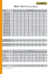
CUTTING DATAStandard values for cutting speeds v cand medium thickness h mfor calculating feed rates by calculating cutting programm »HCT«.MaterialPCarbon steelHardness BrinellCutting speeds v c(sfm)refering to carbide gradeand coatingMG12TN35TI25TF45*H350.2% C 140 - 790 650-11500.4% C 180 - 690 650-980medium thickness of chip h mIndexable Insert Type 314Insert Type311/313/328/108/111/ 116very rigid rigid not rigid very rigid rigid not rigid0.6% C 200 - 520 500-820annealed 180 - 490 590.0039.0020.0012.0020.0012.0004Alloyed steelquenched 280 - 390 520quenched 350 - 230 -Hhigh alloyed steel(>5%)Cast steelannealed 200 - 230 -hardened - - - - - - - - - -unalloyed 180 80 430 -alloyed 220 70 390 -MKStainless steelCast ironmartensitic, ferritic 200 80 590 -austenitic 180 70 390 -low tensile strength 180 70 330 -high tensile strength 250 60 390 -Spheroidal graphitecast ironferritic 160 70 330 -perlitic 250 - 300 -Malleable cast ironSHeat resistant alloy(Fe)ferritic 125 60 330 -perlitic 225 70 200 -annealed 200 40 260 -hardened 275 30 - -.0039.0020.0012.0020.0012.0004Heat resistant alloy(Ni, Co)annealed 250 20 130 -hardened 350 15 - -NAl-alloynot heat treatable 30-80 550 2600 -heat treatable 80-120 220 980 -Al-cast-alloynot heat treatable 80 220 980 -heat treatable 100 100 660 -H10Copper-alloynot heat treatable 90 120 - -heat treatable 100 100 - -In the UNITED STATES call us toll free1 - 888 - 818 HORN*Cermet only indexable insert type 314 available
COMPONENTTorque screw driver with scale- variable torque setting- adjusted torque is shown on displayD 15 VLModel 1-5 NmThe Torque can be infinitely adjusted with a special torquesetter (id.) Ergonomical formed gives perfect handlingabilities. Acustic signal when setted torque is reached.(Standard: EN ISO 6798, BS EN 26789, ASME B 107.14.M.)(Precision: ± 6 %)D 28 VLModel 2-8 NmTorque screw driver with scale- variable torque setting- adjusted torque is shown on displayThe Torque can be infinitely adjusted with a special torquesetter (id.) Ergonomical formed gives perfect handlingabilities. Acustic signal when setted torque is reached.(Standard: EN ISO 6798, BS EN 26789, ASME B 107.14.M.)(Precision: ± 6 %)Torque setterED 28 VLDevice for setting the required torque.Handle: Celluloseacetat with micro structured surfaceBlade: Octogonal (8 flats) blade, hardened galvanizedIn the UNITED STATES call us toll free1 - 888 - 818 HORNO1O
COMPONENTBlade for TORX-Plus screwsDT6PKDT7PKDT8PKDT9PKDT10PKDT15PKDT20PKDT25PKBlade:Utilization:High quality Chrom-Vanadium steel,through hardened, chrome plated.Wiha Chrom Blade guarantees maximumprecison.Colored code greenFor controlled screw setting with definite torquein combination with Wiha torque screw driverhandle.Blade for allen screwsDSW15KDSW20KDSW25KDSW30KDSW40KBlade:Utilization:High quality chrom-vanadium steel,through hardened, chrome plated.Wiha Chrom Blade guarantees maximumprecison.Colored code redcontrolled screw setting with definite torque incombination with Wiha torque screw driverhandelD14ZBKUniversal BitholderFor S.DM08, S.DM10 and S.DM12 alsofor all C6,3 and E6,3 (1/4") BitsBlade: High quality Chrome-Vanadium steel,through hardened, chrome plated.Collar:Utilization:Stainless steelFor controlled screw setting with definite torquein combination with torque screw driver handle.OO2In the UNITED STATES call us toll free1 - 888 - 818 HORN
COMPONENTUniversal Bitholder with T-handleFor S.DM10 and S.DM12also for all C6,3 and E6,3 (1/4") BitsBlade: High quality Chrome-Vanadium steel,through hardened, chrome plated.Collar: Stainless steelUtilization: For controlled opening14ZQKTorque screw driver with scale- variable torque setting- adjusted torque is shown on displayThe Torque can be infinitely adjusted with a special torquesetter (id.) Ergonomical formed gives perfect handlingabilities. Acustic signal when setted torque is reached.(Standard: EN ISO 6798, BS EN 26789, ASME B 107.14.M.)(Precision: ± 6 %)D515QLModel 5-15 NmED515QLTorque setterDevice for setting the required torque.Handle: Celluloseacetat with micro structured surfaceBlade: Octogonal (8 flats) blade, hardened galvanizedIn the UNITED STATES call us toll free1 - 888 - 818 HORNO3O
COMPONENTUniversal BitholderFor S.DM08, S.DM10 and S.DM12 alsofor all C6,3 and E6,3 (1/4") BitsD14ZBQBlade:Collar:Utilization:High quality Chrome-Vanadium steel,through hardened, chrome plated.Stainless steelFor controlled screw setting with definite torquein combination with torque screw driver handle.Blade for TORX-Plus screwsDT15PQDT20PQDT25PQDT27PQDT30PQBlade:Utilization:High quality Chrom-Vanadium steel,through hardened, chrome plated.Wiha Chrom Blade guarantees maximumprecison.Colored code greenFor controlled screw setting with definitetorque in combination with Wiha torque screwdriver handle.OO4In the UNITED STATES call us toll free1 - 888 - 818 HORN
METAL CUTTING SAFETYDuring metal cutting "hot flying chips" may be projected from the workpieceor a rotating part of the machine tool. If carbide is subjected to over-stressor severe impact, it may fracture causing small fragments to be dispelled.In such instances, certains precautions should be implemented to protectthe operator(s) and/or observer(s) against "hot flying chips.Boring operations or applications "tempts" the operator to "lean over" therotating workpiece to check the cutting action. Extra caution should beexercised in doing this and it is recommended that no one practice thishabit while tools or machinery or both are spinning, turning, rotating etc.Grinding products in this catalog will produce dust and/or mist that may behazardous. See material data safety sheets (available upon request).HORN <strong>USA</strong> <strong>Inc</strong>. has no control over conditions to which it's products maybe or subjected to. Therefore it is highly recommended that the user ofHORN <strong>USA</strong> <strong>Inc</strong>. products listed in this catalog and all the literature ofthis company, abide by the standards of use for their particular cuttingmachines and commonly used safety precautions.Designs and/or specifications of products listed in this catalog and allthe literature of HORN <strong>USA</strong> <strong>Inc</strong>. are subject to change without notice.Any modification of these products by the customer or user may voidspecifications and guarantees listed.HORN <strong>USA</strong> <strong>Inc</strong>. cautions every user and/or observer to wear safetyglasses when using any product listed in this catalog and all the literatureof HORN <strong>USA</strong> <strong>Inc</strong>. which made be distributed in conjunction with anyHORN product.In the UNITED STATES call us toll free1 - 888 - 818 HORN
INDEXType Chapter page020 N2605 N7105 N11-N20,N32-N37108 A7-A9,D4,E3110 N21111 A27-A29,D11,D14,D17,E9116 A54-A56,D2923 N31306 A10-A18,D5-D6,E4308 A30-A34,D12,E10311 A43-A44,A47-A49,D21,D23-D24,E15,G4-G5313 A63-A64,A66,A68-A72,D33,D35-D36,E19,G8314 B15-B17,C8-C9,D48,J16-J17325 A82328 A83-A84,A87-A88,D41,G11332 A96-A97,23-24335 A106380 B3,B5,B9,D44,D46380...IK B6-B7381 B13,J2-J11,J14382 C3-C4383 C6-C7606 A19-A20,D7,E5,6-7608 A35,D13,D15,E11611 A45-A46,D22,E16,F4613 A67,D34,D37,E20,F8628 A85-A86,A89,D42,E23,F12632 A98-A99636 A100-A101A110 N38ABS..380 B11B105 N8-N9, N41-N48B110 N10, N49BKT N25,N29-N30DA31 L12DA32 L13DAM31 L2-L4,L6-L7DAM32 L3-L4,L6-L7DM008 K3,K5,K7DM010 K13,K15,K17DM012 K23,K25,K27DM208 K8-K11DM210 K18-K21DM212 K28-K31DMU008 K2,K4,K6DMU010 K12,K14,K16DMU012 K22,K24,K26DSA M58-M60DSAK M62-M63DSAKH M61DSAR M64DSAT M65DSDH M32DSDS M31DSF M42-M43DSK M24,M26-M27DSKK M6DSKL M25DSKM M28-M30DSKMK M10DSM M37DSMK M8DSML M40DSMMK M11DSMR M38-M39DSMRK M9TypeDSPDSPKDSPLDSPMDSPTDSRDSRFDSRRDSTDSTKHSK..380L311L313M116M275M306M306.ERM306.STM308M308.ERM308.STM310M311M311.ERM311.STM313M313.ERM313.STM328M328.ERM328.STM332M332.ERM335MDMU116MU306MU308MU310MU311MU313MU328N314S275S310SM328U108U111U116U306U308U311U313U314U325U328U380U381U382U383Chapter pageM51-M52,M55M48-M49M55M53-M54M50M41M44M45M33-M36M7B10A50A73-A74A53,D26J12-J13A3-A4,D3,E2A6A5A23-A24,D9,E8A26A25C13,C15A39-A40,D19,F2,G3A42,F3A41A59-A60,D31,F6,G7A62,F7A61A77-A79,E22,F10,G10A81,F11A80A92-A94A95A104-A105L8-L11A52,D25A2,D2A22,D8C12,C14A38,D18,E14,G2A58,D30,E18,G6A76,G9C8,J16J15C16D38A7-A9A27-A29,D16A54,A56,D28A10,A18A30,A34A43,A49A64-A65,A72B14A82A83B2,B4,B8,D43,D45B12C2C5In the UNITED STATES call us toll free1 - 888 - 818 HORN