Type 1 1 4 - Horn USA, Inc.
Type 1 1 4 - Horn USA, Inc.
Type 1 1 4 - Horn USA, Inc.
- No tags were found...

You also want an ePaper? Increase the reach of your titles
YUMPU automatically turns print PDFs into web optimized ePapers that Google loves.
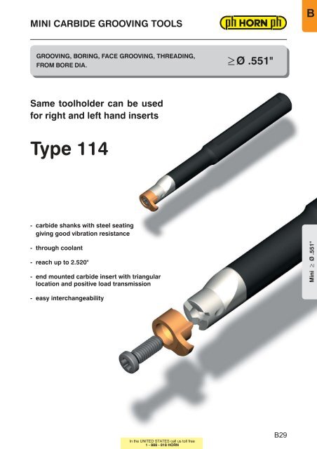
MINI CARBIDE GROOVING TOOLSBGROOVING, BORING, FACE GROOVING, THREADING,FROM BORE DIA. —Ø .551 "Same toolholder can be usedfor right and left hand inserts<strong>Type</strong>114− carbide shanks with steel seatinggiving good vibration resistance− through coolant−reachupto2.520"− end mounted carbide insert with triangularlocation and positive load transmission− easy interchangeabilityIn the UNITED STATES call us toll freeB29
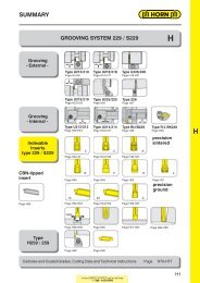
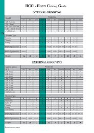
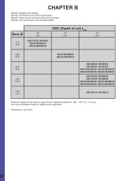
HCG - H orn C atalog G uideINTERNAL GROOVINGBore ØPRODUCT LINESUPER MINI MINI 21 7 264 S223 S224 231 S229/229 S31 2/31 2 31 5up to .31 5" (8 mm).315−.709"(8−18mm).709 − 1 .1 02" (1 8 − 28 mm)1.102−1.496"(28−38mm)from 1 .496" (38 mm)MachiningBoringGrooving and turningThreadingProfilingWidth of Groove in inchWidth of Groove in mm.039−.079" .028−.1 57" .020−.250" .059−.1 1 8" .079−.1 1 8" .079−.236" .098−.394" .098−.394" .020−.250" .043−.1 63"1 .0−2.0mm 0.7−4.0mm 0.5−6.35mm 1 .5−3.0mm 2.0−3.0mm 2.0−6.0mm 2.5−1 0mm 2.5−1 0mm 0.5−6.35mm 1 .1 −4.1 5mmChapter A B C D E F G H J KEXTERNAL GROOVINGDepth ofGroovePRODUCT LINESUPER MINI MINI 21 7 264 S223 S224 231 S229/229 S31 2/31 2 31 5up to .1 57" (4 mm)up to .236" (6 mm)up to .31 5" (8 mm)up to .394" (1 0 mm)up to .551 " (1 4 mm)up to .709" (1 8 mm)up to 1 .000" (25 mm)MachiningGroovingSide turningParting offThreadingProfilingWidth of Groove in inchWidth of Groove in mm.039−.079" .028−.1 57" .020−.250" .059−.1 1 8" .079−.1 1 8" .079−.236" .098−.394" .098−.394" .020−.250" .043−.1 63"1 .0−2.0mm 0.7−4.0mm 0.5−6.35mm 1 .5−3.0mm 2.0−3.0mm 2.0−6.0mm 2.5−1 0mm 2.5−1 0mm 0.5−6.35mm 1 .1 −4.1 5mmChapter A B C D E F G H J KIn the UNITED STATES call us toll free
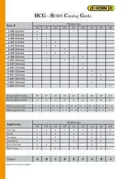
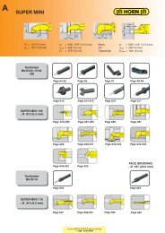
SUMMARYBMINI CARBIDE GROOVING TOOLSBMINI U108/108— Ø.315"Toolholder Page B2Page B3−B6 Page B7−B1 0 Page B1 1Page B1 2MINI U111/111— Ø.433"Toolholder Page B1 4Page B1 5−B1 8 Page B19−B22 Page B23Page B24−B28MINI U114/114— Ø.551"Toolholder Page B30Page B33Page B32−B37Page B36Page B38−B40Page B41Page B42−B44Page B45−B48MINI U116/116— Ø.630"Toolholder Page B50Page B51 −B54 Page B55−B56 Page B57Page B58−B62Cartridge— Ø .787"<strong>Type</strong> 1 25/1 45Page B63Technical Instructions Page B64−B67In the UNITED STATES call us toll freeB1
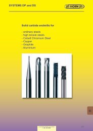
a fwGROOVING (Internal) —Ø.551"TOOLHOLDER typeBU114/B114with through coolantBore Ø from .551 "Depth ofgroove up to .1 57"Width of groove up to .157"Material of shank: Carbide −Giving a good vibration resistance.354for use with insert.433ht max <strong>Type</strong> U11 4114l 1l 2l 4.20d g6Right hand insert shownPart number l 1 l 2 l 4 d g6 f a h t max Width ofgroove wMini — Ø.551"<strong>Inc</strong>h ToolholderBU11 4.ST05.00* 2.953 .748 1 .57BU11 4.0500.01 3.937 1 .338 1 .97BU11 4.0500.02 4.330 1 .771 1 .97BU11 4.0500.03 5.118 2.520 1.97.500 .354 .543 .460 .157BU11 4.ST06.00* 3.1 50 .748 1 .57BU114.0625.01 3.937 1 .338 1 .97BU114.0625.02 4.330 1 .771 1 .97BU114.0625.03 5.118 2.520 1.97.625 .354 .543 .585 .157up to .1 57Metric Toolholder in mmB114.0012.00 75 1 9 40B114.0012.01 100 34 50B114.0012.02 110 45 50B114.0012.03 130 64 50B114.0016.00 80 1 9 40B114.0016.01 100 34 50B114.0016.02 110 45 50B114.0016.03 130 64 50* Steel Toolholder12 9 13.8 11 416 9 13.8 15 4up to 4.0Dimensions in inch /mmSpare partsToolholder Screw Torx screw driverBU/B1 1 4... 4.1 2T1 5E T1 5NoteToolholders can be used with right and lefthandinserts.Further shank sizes upon request.Toolholders with damaged seating can be repairedby HORN <strong>USA</strong>.B30In the UNITED STATES call us toll free
FACE GROOVING —Ø.472"BTOOLHOLDER typeR/L HCU114Outer groove Ø from .472"Depth ofgroove up to .236"Width of groove up to .1 25".354l 1for use with insertØ.354fh 1h <strong>Type</strong> U11 4114seepageB45-B48b 1b 2bl 2Left hand insert shownPart number l 1 l 2 b b 1 b 2 h h 1 f t max Width ofgroove wb1=*s+b2R/L HCU114.0500.01 3.819 3.937 .500 .579 .500 .638 .461R/L HCU114.0625.01 4.803 4.921 .625 .697 .625 .764 .586R/L HCU114.0750.01 4.803 4.921 .750 .835 .750 .888 .711*s = see inserts page B45-B48Dimensions in inchFurther shank sizes upon requestup to .236up to .1 25NoteRight hand toolholders uses left hand inserts.Left hand toolholders uses right hand inserts.Spare partsToolholder Screw Torx screw driverR/L HCU114... 4.12T1 5E T1 5In the UNITED STATES call us toll freeB31
GROOVING Internal —Ø.551"BINSERT typeS1 1 4Bore Ø from .551 "Depth of groove up to .1 57"Width of groove up to .1 1 8"ffor use with toolholderD mind <strong>Type</strong> BU11 4B114wst maxToolholder faceR = right hand version shownL = lefthandversionPart number w +.002 r s f d t max D minR/L S1 1 4.0200.D2 .078R/L S114.0250.D2 .098 .008 .209 .354 .354 .157 .551R/L S1 1 4.0300.D2 .118State R or L versionDimensions in inchCarbide gradesMG12TN35TI25TF45· StandardSemistandardPlease check price anddelivery for all itemsIn the UNITED STATES call us toll freeB33
NC−PROFILING (Internal) —Ø.551"INSERT <strong>Type</strong>U114/114Bore Ø from .551 "Width of groove .031 − .1 25"ffor use with toolholderd <strong>Type</strong> BU11 4B114D minrwrswith corner radiust maxToolholder faceR = Right hand version shownL = Left hand versionMini — Ø.551"Part number w +.001 2 r s f d tmax D minR/L U114.0031.08 .031R/L U114.0046.08 .046R/L U114.0062.08 .062 .008 .209 .354 .354 .157 .551R/L U114.0078.08 .078R/L U114.0094.08 .094R/L U114.0125.08 .125R/L U114.0046.16 .046R/L U114.0062.16 .062R/L U114.0078.16 .078 .016 .209 .354 .354 .157 .551R/L U114.0094.16 .094R/L U114.0125.16 .125R/L 114.0200.02 .079 .008 .209 .354 .354 .157 .551Carbide gradesMG12TN35TI25TF45· StandardSemistandardPlease check price anddelivery for all itemsState R or L version.Dimensions in inchB34In the UNITED STATES call us toll free
GROOVING (Internal) —Ø.551"BINSERT <strong>Type</strong>U114/114Bore Ø from .551 "Width ofgroove .046 − .1 25"ffor use with toolholderD mind <strong>Type</strong> BU11 4B114wst maxToolholder faceR = Right hand version shownL = Left hand versionPart number w +.001 2 s f d t max D minR/L U114.0046.00 .046R/L U114.0056.00 .056R/L U114.0062.00 .062R/L U114.0078.00 .078 .209 .354 .354 .157 .551R/L U114.0094.00 .094R/L U114.0125.00 .125R/L 114.0110.00 .047R/L 114.0130.00 .055R/L 114.0150.00 .059R/L 114.0160.00 .067 .209 .354 .354 .157 .551R/L 114.0200.00 .079R/L 114.0250.00 .098State R or L version.Dimensions in inchCarbide gradesMG12TN35TI25TF45· StandardSemistandardPlease check price anddelivery for all itemsIn the UNITED STATES call us toll freeB35
GROOVING Internal —Ø .650"INSERT <strong>Type</strong>U114/114Bore-Ø from .650"Depth ofgroove up to .256"Width of groove .062 − .1 25"ffor use with toolholderD mind <strong>Type</strong> BU1 1 4B114rwrt maxsToolholder faceGrooving inserts withextended depth ofcutR = Right hand version shownL = Left hand versionPart number w +.001 2 r s f d t max D minCarbide gradesMG1 2TN35TI25TF45Mini — Ø.650"R/L U114.0062.1.08 .062R/L U114.0078.1.08 .078R/L U114.0094.1.08 .094R/L U114.0125.1.08 .125R/L 114.0150.1.02 .059R/L 114.0200.1.02 .079R/L 114.0250.1.02 .098R/L 114.0300.1.02 .118.008 .445 .209 .354 .256 .650.008 .445 .209 .354 .256 .650· StandardSemistandardPlease check price anddelivery for all itemsState R or L version.Dimensions in inchIntermediate widths upon request.B36In the UNITED STATES call us toll free
GROOVING Internal —Ø.551"BINSERT <strong>Type</strong>U114/114Bore Ø from .551 "Full radius up to r .062"ffor use with toolholderd <strong>Type</strong> BU1 1 4B114D minrwsFull radiust maxToolholder faceR = Right hand version shownL = Left hand versionPart number w +.002 r s f d t max D minR/L U114.0031.62 .062 .031R/L U114.0039.78 .078 .039R/L U114.0047.94 .094 .047R/L U114.0062.12 .1 25 .062.209 .354 .354 .1 57 .551R/L 1 1 4.0006.1 2 .047 .024R/L 114.0009.18 .071 .035R/L 1 1 4.001 0.20 .079 .039 .209 .354 .354 .1 57 .551R/L 114.0011.22 .087 .043R/L 114.0015.30 .1 1 8 .059Carbide gradesMG1 2TN35TI25TF45· StandardSemistandardPlease check price anddelivery for all itemsState R or L version.Dimensions in inchIn the UNITED STATES call us toll freeB37
BORING and PROFILING —Ø.543"INSERT <strong>Type</strong>114Bore Ø from .543"max. depth of undercut .051 "fd5˚for use with toolholder <strong>Type</strong> BU1 1 4B114D min8˚rws18˚Toolholder faceR = Right hand version shownL = Left hand versionMini — Ø.543"Part number w r s f d t max D minR/L 1 1 4.1 890.02 .1 38 .008 .209 .343 .354 .051 .543State R or L version.The modified geometry allows boring of bores — Ø.543"and profiling ofreliefsasperDIN509form E and F.Dimensions in inchCarbide gradesMG1 2TN35TI25TF45· StandardSemistandardPlease check price anddelivery for all itemsB38In the UNITED STATES call us toll free
BORING and PROFILING —Ø.539"BINSERT <strong>Type</strong>114Bore Ø from .539"max. depth of undercut .1 97"ffor use with toolholderd <strong>Type</strong> BU1 1 4B114D minr8˚st max47˚Toolholder faceR = Right hand version shownL = Left hand versionPart number r s f d t max D minCarbide gradesMG1 2TN35TI25TF45R/L 1 1 4.4787.02 .008 .209 .343 .354 .1 1 8 .539R/L 114.4710.02 .008 .209 .433 .354 .1 97 .630State R or L version.Dimensions in inch· StandardSemistandardPlease check price anddelivery for all itemsThe modified geometry allows boring of bores— Ø 0.539"and profiling ofreliefsasperDIN509form E and F.In the UNITED STATES call us toll freeB39
BACKBORING (Internal)INSERT <strong>Type</strong>114Bore Ø from .543"max. depth of undercut .1 38"ffor use with toolholderd <strong>Type</strong> BU1 1 4B114D min30˚rss 1t maxToolholder faceMini — Ø.551"R = Right hand version shownL = Left hand versionPart number s 1 r s f d t max D minCarbide gradesMG1 2TN35TI25TF45R/L 1 1 4.3090.02 .094 .008 .21 3 .343 354 .1 38 .543State R or L version.Dimensions in inch· StandardSemistandardPlease check price anddelivery for all itemsB40In the UNITED STATES call us toll free
PREGROOVING and CHAMFERING (Internal)BINSERT <strong>Type</strong>114Bore Ø from .543"ffor use with toolholderd <strong>Type</strong> BU1 1 4B114D min8˚.008wts45˚Toolholder facet1R = Right hand version shownL = Left hand versionPart number w s f d t t 1 D minCarbide gradesMG1 2TN35TI25TF45R/L 114.0815.45 .059 .209 .343 .354 .008 .059 .543State R or L version.Dimensions in inch· StandardSemistandardPlease check price anddelivery for all itemsIn the UNITED STATES call us toll freeB41
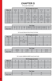
THREADING (Internal) partial profileINSERT <strong>Type</strong>114TPI 9 − 64Pitch in mm(0.5 − 3.0 mm)ffor use with toolholderd <strong>Type</strong> BU1 1 4B114D minXs60˚Detail XPartial profile threadEToolholder faceR = Right hand version shownL = Left hand versionMini — Ø.551"Part number Pitch E s f d D minSTANDARD THREAD tpi mmR/L 1 1 4.1 020.01 11−16 (1.75−2.5)R/L 114.1325.01 9−1 2 (2.5−3.0).1 65 .21 3 .354 .354 .551Part number Pitch E s f d D minFINE THREAD tpi mmCarbide gradesMG1 2TN35TI25TF45· StandardSemistandardPlease check price anddelivery for all itemsR/L 114.0205.01 28−64 (0.5−0.75) .1 89R/L 114.0510.01 18−32 (1.0−1.25) .185 .213 .354 .354 .551R/L 114.0815.01 12−20 (1.5−1.75) .177State R or L version.Dimensions in inch(mm)B42In the UNITED STATES call us toll free
THREADING (Internal) full profileBINSERT <strong>Type</strong>114Bore from .551 "Pitch P1 .0 − 2.5 mmffor use with toolholderd <strong>Type</strong> BU1 1 4B114D minXs60˚Detail XEMetric ISO threadToolholder faceR = Right hand version shownL = Left hand versionPart number Pitch E s f d D minin mmSTANDARD THREADCarbide gradesMG1 2TN35TI25TF45R/L 1 1 4.1 020.02R/L 114.1325.022.0 mm2.5 mm.1 65 .21 3 .354 .354 .551· StandardSemistandardPart number Pitchin mmE s f d D minFINE THREADPlease check price anddelivery for all itemsR/L 114.0510.02 1.0mm .189 .21 3 .354 .354 .551R/L 114.0815.02State R or L version.1.5mm .177Dimensions in inch/mmIn the UNITED STATES call us toll freeB43
THREADING (Internal) partial profileINSERT type114Bore Ø from .551 "Pitch P4.0 − 5.0 mmffor use with toolholderd <strong>Type</strong> BU1 1 4B114D minXsb30˚Detail XMetric ISO trapezoidalthread DIN1 03EToolholder faceR = Right hand version shownL = Left hand versionMini — Ø.551"Part number Pitch b E s f d D minin mmR/L 114.2240.01 4.0 .052R/L 114.2750.01 5.0 .067State R or L version..1 57 .21 7 .354 .354 .551Dimensions in inch/mmCarbide gradesMG1 2TN35TI25TF45· StandardSemistandardPlease check price anddelivery for all itemsB44In the UNITED STATES call us toll free
FACE GROOVING InternalBINSERT <strong>Type</strong>U114/114Depth ofgroove up to .236"Width of groove .039 − .1 25"Outer groove Ø .472"ffor use with toolholder.354D min <strong>Type</strong> BU11 4B114t maxwrrsR = Right hand version shownL = Left hand versionPart number w +.001 2 r s f t max D minCarbide gradesMG12TN35TI25TF45R/L U114.1246.00 .046 - .059R/L U114.1262.00 .062 .008 .098R/L U114.1278.00 .078 .008 .327 .295 .118 .472R/L U114.1294.00 .094 .008 .118R/L U114.1225.00 .125 .008 .118R/L 114.1210.00 .039 − .059R/L 114.1215.00 .059 .008 .098R/L 114.1220.00 .079 .008 .327 .295 .118 .472R/L 114.1225.00 .098 .008 .118R/L 114.1230.00 .118 .008 .118· StandardSemistandardPlease check price anddelivery for all itemsR/L 114.1220.5.00 .079 .425 .197R/L 114.1225.5.00 .098 .008 .425 .295 .197 .472R/L 1 1 4.1 230.6.00 .118 .465 .236State R or L version.Dimensions in inchNOTE:R = rotation counter-clockwise!Using the face−grooving insert type U1 1 4/1 1 4 on toolholder BU/B1 1 4the sizes l 1 and l 2 will be enlarged by .1 1 8"In the UNITED STATES call us toll freeB45
FACE GROOVING InternalINSERT <strong>Type</strong>U114Depth ofgroove up to .1 1 8"Width of groove .046 − .1 25"Outer groove Ø .472".354fD minfor use with toolholder <strong>Type</strong> BU11 4B114t maxwrsFull radiusR = Right hand version shownL = Left hand versionMini — Ø.551"Part number w +.002 r s f t max D minR/L U114.1223.46 .046 .023 .059R/L U114.1231.62 .062 .031 .098R/L U114.1239.78 .078 .039 .327 .295 .118 .472R/L U114.1247.94 .094 .047 .118R/L U114.1262.12 .125 .062 .118State R or L version.Dimensions in inchCarbide gradesMG12TN35TI25TF45· StandardSemistandardPlease check price anddelivery for all itemsNOTE:R = rotation counter-clockwise!Using the face−grooving insert type U1 1 4/1 1 4 on toolholder BU/B1 1 4the sizes l 1 and l 2 will be enlarged by .1 1 8"B46In the UNITED STATES call us toll free
FACE GROOVING InternalBINSERT <strong>Type</strong>U114/114Depth ofgroove up to .236"Width of groove .039 − .1 25"Outer groove Ø .551 "fD minfor use with toolholder.354 <strong>Type</strong> BU11 4B114t maxwrrsR = Right hand version shownL = Left hand versionPart number w +.001 2 r s f t max D minCarbide gradesMG12TN35TI25TF45R/L U114.1446.00 .046 - .059R/L U114.1462.00 .062 .008 .098R/L U114.1478.00 .078 .008 .327 .354 .118 .551R/L U114.1494.00 .094 .008 .118R/L U114.1425.00 .125 .008 .118R/L 114.1410.00 .039 − .059R/L 114.1415.00 .059 .008 .098R/L 114.1420.00 .079 .008 .327 .354 .118 .551R/L 114.1425.00 .098 .008 .118R/L 114.1430.00 .118 .008 .118· StandardSemistandardPlease check price anddelivery for all itemsR/L 114.1420.5.00 .079 .406 .197R/L 114.1425.5.00 .098 .008 .406 .354 .197 .551R/L 1 1 4.1 430.6.00 .118 .445 .236State R or L version.Dimensions in inchNOTE:R = rotation clockwise!Using the face−grooving insert type U1 1 4/1 1 4 on toolholder BU/B1 1 4the sizes l 1 and l 2 will be enlarged by .1 1 8"In the UNITED STATES call us toll freeB47
FACE GROOVING InternalINSERT <strong>Type</strong>U114Depth ofgroove up to .1 1 8"Width of groove .039 .1 25"Outer groove Ø .551 ".354fD minfor use with toolholder <strong>Type</strong> BU11 4B114t maxwrFull radiussR = Right hand version shownL = Left hand versionMini — Ø.551"Part number w +.002 r s f t max D minR/L U114.1423.46 .046 .023 .059R/L U114.1431.62 .062 .031 .098R/L U114.1439.78 .078 .039 .327 .354 .118 .551R/L U114.1447.94 .094 .047 .118R/L U114.1462.12 .125 .062 .118R/L 114.1410.05 .039 .020 .059R/L 114.1416.08 .063 .031 .098R/L 114.1420.10 .079 .039 .327 .354 .118 .551R/L 114.1425.12 .098 .049 .118R/L 114.1430.15 .118 .059 .118Carbide gradesMG12TN35TI25TF45· StandardSemistandardPlease check price anddelivery for all itemsState R or L version.Dimensions in inchNOTE:R = rotation clockwise!Using the face−grooving insert type U1 1 4/1 1 4 on toolholder BU/B1 1 4the sizes l 1 and l 2 will be enlarged by .1 1 8"B48In the UNITED STATES call us toll free
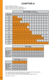
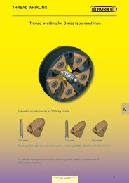
TECHNICAL INFORMATIONS − ThreadingRECOMMENDED NUMBER OF PASSESCarbide grade Steel (thousands oflb/in 2 ) Stainl.steel Cast iron AluminiumTN35 58−72 72−1 01 1 01 −1 23 1 23−1 67 > 1 67Vmaxfeet/min 525 460 390 300 230 300 330 980Pitchmm tpiNo. ofpasses0,8 32 8 8 9 9 1 0 1 0 9 81,0 24 10 10 12 12 12 12 12 101,25 20−19 12 12 14 14 15 15 14 121,5 16 15 15 17 17 18 18 17 151,75 14 17 17 19 19 21 21 18 172,0 1 2−1 1 1 9 20 22 22 25 25 20 1 82,5 10 22 24 26 26 31 31 22 203,0−3,5 8 28 30 32 32 38 38 24 22FEED DIRECTION AND SPINDLE ROTATION for internal threadingRight hand thread (internal)Left hand thread (internal)RIGHT HAND TOOLINGLEFT HAND TOOLINGLEFT HAND TOOLINGRIGHT HAND TOOLINGIN−FEEDRADIAL IN−FEEDMetal removed on both sides ofthe insertsimultaneously. Themost commonly used method for thread production.MODIFIED FLANK IN−FEEDLess wear of the trailing edge and better surface finish oncorresponding flank.radial in−feedmodified flank in−feedALTERNATING FLANK IN−FEEDBoth edges are being fully utilised which means longerinsert life.Technical InstructionsFLANK IN−FEEDMore easily formed chip and better heat dissipation.B64alternating flank−in feedIn the UNITED STATES call us toll freeflank in−feedAll threads up to 4.5˚ helix angle can be manufactured with HORN standard threading inserts.No special anvils will be necessary.
TECHNICAL INSTRUCTIONSABSEATINGSof MINI as well as SUPER − MINI guarantee the accurate center height of these tools.In spite ofthis always check center height because a difference may cause problemsespecially when machining small diameters.TORQUE OF SCREWS FOR MINIFollowing torques are allowed for screws of MINI inserts. We recommend not to use additionalmeans (such as copper paste) for screws.Screw T8(type108) T10(type111) T15(type114) T20(type116)Torque lbf-in. 9 − 1 3 22 − 26 35 − 40 50 − 55REMOVAL OF CHIPSPlease choose inserts with small cutting widths, which helps chips evacuation and chip flowout of the bore beside the tool. To avoid jam of chips use the technique to groove by steps.COOLANTUse a filtered coolant for transporting the chips out and for cooling the insert itself.A coolant pressure of75 psi min. is recommended.UNCOATED GRADESMG1 2 −a universal grade with good wear resistance. Used at low or medium cutting speeds formachining steel, cast iron and non ferrous materials.COATED GRADESTN35 −TI25 −TF45 −a very popular grade TIN coated used to low or medium cutting speeds. Also recommendedfor machining stainless steel or exotic alloyed materials.a TICN coated grade with high abrasion resistance. Recommended for machining steel andnon ferrous materials at medium cutting speeds.a TIALN coated grade. This coating has a very high temperature stability and high hardness.Machining small bores, therefore it is only used for special applications.In the UNITED STATES call us toll freeB65
GRADES and CUTTING SPEEDSwear resistancecutting speedtoughnessCarbide grades synthetic cutting-tool materialuncoated coatedPD1 0PD20TF45TI25MG1 2TN35 TF45MG1 2CB1 0feedrateCB20ISOANSINnon ferrous metalhigh temperaturematerialsSHhardened materialswear resistancecutting speedtoughnessfeedrateCarbide gradesuncoated coatedMG1 2TN35TI25MG1 2TN35 TI25TI25MG1 2TN35TF45TF45TF450110203040102030Technical Instructions4001102030C8C7C5----C4C3C2C1B66ANSIISOC8C7C5----C4C3C2C101102030401020304001102030Psteel stainless steel grey cast iron / aluminiumMIn the UNITED STATES call us toll freeK
GRADES and CUTTING SPEEDSABNominal cutting speeds with HORN gradesISO Material SUPERMINI® MINIFeed rates IPRHardnessBrinell.0004 − .0008 .0004 − .001 2.0008 − .0020 .0012 − .0040.0008 − .0020 .0004 − .0012Cutting speed *Vc ft/minPHB MG1 2 TN35 TI25 TF45 CB1 0/CB20Non−alloy carbon steelC 0,4% < 0,6% 1 50 45 − 360 45 − 590 45 − 590 45 − 590C > 0,6% < 0,8% 200Low−alloy steelAnnealed 1 80Hardened and tempered 275 50 − 300 50 − 500 50 − 500Hardened and tempered 300High−alloy steelAnnealed 200Hardened 32560−30060−300Steel castingsNon−alloy 1 80Low−alloy 200 60 − 360 60 − 590 60 − 590High−alloy 225Stainless steel, annealedMartensitic / ferritic 200 60 − 300 60 - 300MStainless steelAustenitic Ni > 8% 1 80 50 − 265Cr 1 8−25%Grey cast iron 1 80 − 260 50 − 300 50 − 500 50 − 500 50 − 500KModular SG iron 1 80 − 260 50 − 300 50 − 430 50 − 430 50 − 500Malleable iron 1 30 − 230 50 − 430 50 − 430 50 − 500Heat resistant alloys (NiFe) 60 - 250 60 - 250SHeat resistant alloys (NiCo) 60 - 1 30 60 - 1 30Aluminium alloys 50 − 725 50 − 2000 50 − 2000NBronze−brass alloys 50 − 725 50 − 2300 50 − 2300Hhardended materials>54HRC65 - 460*Vcis depending on the bore diameter and therefore ofthe maximum numbers ofrevolutions ofthe machine.In the UNITED STATES call us toll freeB67