MAG-Manual - Refurbished Vending Machines
MAG-Manual - Refurbished Vending Machines
MAG-Manual - Refurbished Vending Machines
Create successful ePaper yourself
Turn your PDF publications into a flip-book with our unique Google optimized e-Paper software.
TABLE OF CONTENTSSection 1: General InformationIntroduction 4Models 4For Your Records 4Features 4After Unpacking 4Main Logic Board Assembly 5Specifications 5Dimensional Drawing 6Section 2: InstallationOption Switch Settings 7Installing the Bill Validator 7Section 3: OperationBill Recognition 8Bill Validation 8Bill Stacking and Credit 8Bill Rejection 8Component ExplanationBill Transport and Stacking 8Left and Right Alignment Sensors 8Center Optic Sensor 8Left and Right Optic Sensor 8Magnetic Sensor 8Anti-Pullback Levers 8Stacker Home Sensor 8Encoder Sensor 8Component Explanation Drawing 9Interconnect Drawing (<strong>MAG</strong>50B/52B) 10Interconnect Drawing (<strong>MAG</strong>50SA/52SA) 11Section 4: MaintenanceDisassembling the <strong>MAG</strong> 12Disassembling the Chassis 15Disassembling the Lower Housing 17<strong>MAG</strong>50 Cleaning Maintenance Procedure 19Cleaning Salt Water Damage 20Section 5: TroubleshootingIntroduction 21<strong>MAG</strong> Diagnostic Flash Codes 21Troubleshooting Guide 22Section 6: Parts ListMain Frame (<strong>MAG</strong>50B/52B/52BX) 27Main Frame (<strong>MAG</strong>50SA/52SA) 28Chassis 29Lower Housing Assembly 31Logic Board and Case Assembly 32Intermediate Frame Assembly 33Cashbox Assembly 33Harnesses 343
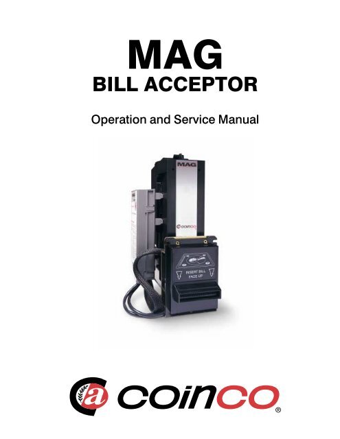
SECTION 1: GENERAL INFORMATIONINTRODUCTIONThis manual contains information on installing, operatingand maintaining Coinco's <strong>MAG</strong> Series bill acceptorsThis manual is intended for owners, route operators andshop-level technicians as a primary source of informationTaking time to read this manual and becomingfamiliar with this information will help you obtain thebest performance from your Coinco bill acceptorMODELS<strong>MAG</strong> Series bill acceptors are self-contained unitsdesigned to work with existing vending machine interfaces,plus MDB vendors Listed below are some of themodels available:<strong>MAG</strong>50B<strong>MAG</strong>52BX<strong>MAG</strong>50SA<strong>MAG</strong> bill acceptor, 500 capacitystacker, 110V AC, Bottler interfaceand mask<strong>MAG</strong> bill acceptor, 500 capacitystacker, 24V DC, Bottler mask, MDBinterface only<strong>MAG</strong> bill acceptor, 500 capacitystacker, 110V AC, Snack interface andmask, Additional length harness<strong>MAG</strong>50B bill acceptors are primarily used in cold drinkvendors which use either the electromechanical, electronic,or MDB interface This bill acceptor uses the"bottler" interface, which communicates to the vendorthrough either HIGH LEVEL or MDB communication<strong>MAG</strong>52BX supports MDB communication only<strong>MAG</strong>50SA and <strong>MAG</strong>52SA bill acceptors are primarilyused in either electronic or MDB snack, coffee or foodmachines These bill acceptors use the "snack" interfaceand communicate to the vendor through either PULSE,SERIAL, PARALLEL or MDB communicationFOR YOUR RECORDSA label indicating the model number and serial number isaffixed to the back of the bill acceptor Refer to themodel and serial number whenever you call upon yourCoinco Service Center for information or service Thefirst four digits of the serial number contain the manufacturingdate code which indicates the beginning of thewarranty periodEXAMPLE: Serial number 269900135 First andsecond digits indicate the week of manufacture Thethird and fourth digits indicate the year (the 26th weekof 1999)FEATURES• Modular design• Bill Hold Feature• Center drive belt• Scalloped bill path for wet bill acceptance• State-of-the-art electronic logic system• Switch selectable acceptance of the following bills: $1,$2, $5, $10 and $20• High capacity bill box• Vandal resistant design protects against: saltwater, billpullback, counterfeit bills• Utilizes standard mounting and electrical interfaces• 110 and 24 VAC and 24 VDC Multi-Drop Businterfaces available• High impact, non-corrosive plastic construction• Easily accessible bill path• Self-diagnostics communicated via status light• Standard/High Level security switch• Switch selectable acceptance of bills face up, in one orboth directions• Optional hasp for locking bill box• Manufactured and supported by Coinco• Made in the USAAFTER UNPACKINGAfter unpacking the unit, inspect it for any possibleshipping damage If the unit is damaged, notify theshipping company immediately Only the co-signee (theperson or company receiving the unit) can file a claimagainst the carrier for shipping damage We recommendthat you retain the original carton and packing materialsto reuse if you need to transport or ship your acceptor inthe futureIf the bill acceptor is being stored or used as a spare,always keep it in its shipping carton when not in useThis will keep it clean and offer the best protection forthe unit4
SECTION 1: GENERAL INFORMATIONMAIN LOGIC BOARD ASSEMBLYThe main logic board contains the microprocessor whichcontrols all the functions of the bill acceptor based oninformation from the vending machine, coin mechanismand various bill acceptor sensorsAlso contained on the main logic board is the powersupply which receives its primary voltage from thevending machine For 117VAC units, the primary ACvoltage is routed to the transformer in the bill acceptorwhere it is reduced to 24VAC This 24VAC is thenrouted back to the main logic board where it is rectifiedand filtered for logic board operation For 24VAC and 24VDC (MDB) units, no transformer is needed Theprimary voltage is rectified and filtered on the main logicboardSPECIFICATIONSPower Requirements<strong>MAG</strong>50B, <strong>MAG</strong>50SA — 117V AC95 to 130 VAC, 60 Hz02 Amp max standby075 Amp max operating<strong>MAG</strong>52B, <strong>MAG</strong>52SA — 24V AC20 to 32 VAC, 60 Hz02 Amp average standby25 Amp average operating<strong>MAG</strong>52BX--24V DC22 to 45 VDC02 Amp average standby25 Amp average operatingOperating Temperature0°F to 150°F-18°C to 65°CStorage Temperature-22°F to 165°F-30°C to 74°CRelative Humidity5% to 95% non-condensingPhysical Weight in Shipping Carton57 pounds - 117VAC4 pounds - 24VACPhysical Dimensions<strong>MAG</strong>30B <strong>MAG</strong>50B <strong>MAG</strong>70BHeight 1116 inches 1116 inches 1116 inchesfrom top of bill box to bottom of mounting plateWidth 526 inches 526 inches 526 inchesfrom logic board cover to mounting plateDepth 429 inches 492 inches 617 inchesfrom mounting plate to back of stacker5
SECTION 1: GENERAL INFORMATIONDimensions11.166.803.255.204.591.332.00.99<strong>MAG</strong>xxB3.255.263.741.74<strong>MAG</strong>xxSA3.323.322.852.874.232.262.914.241.001.804.23.534.97Depth1.21DepthB models SA models<strong>MAG</strong>30 4.29 5.03<strong>MAG</strong>50 4.92 5.66<strong>MAG</strong>70 6.17 6.91<strong>MAG</strong>90 8.67* 9.41**Add 0.25 for metal cashboxDepth6
SECTION 2: INSTALLATIONOPTION SWITCH SETTINGS<strong>MAG</strong> bill acceptors contain an option switch bank on themain logic board which allows the unit to be customizedto the requirements of the individual account This switchbank is factory set with switch 3 and 8 in the ON positionand 1, 2, 4, 5, 6, and 7 in the OFF positionSetting Option Switches (see Figure 1)Remove power from the bill acceptor Remove the billbox Located on the side of the logic board cover is theoption switch access hole Insert a small screwdriverthrough the access hole to set the option switches asdesired (see Figure 2) Reinstall the bill box Applypower and test for proper operationFigure 1<strong>MAG</strong>**B Option Switch Settings(see Figure 2)SWITCH ON OFF1 High Security Standard Acceptance2 Accepts bills in one Accepts bills in bothdirections only (face directions (face up)up, green seal first)3 Standard credit pulse Short credit pulse150ms on 150ms off 50 ms on 50 ms off4 $20 Accept $20 Reject5 $10 Accept $10 Reject6 $5 Accept $5 Reject7 $2 Accept $2 Reject8 $1 Accept $1 Reject (see note)NOTE: The 407982 logic board with software67090 will accept $100 bills with Switch 8 "OFF",if no other bills are enabled This is the maximumaccept modeACCESS HOLEOPTION SWITCH#8#1If however, another bill switch is "ON", then $100bills will be rejected if Switch 8 is "OFF"<strong>MAG</strong>**SA Option Switch Settings(see Figure 2)SWITCH ON OFF1 High Security Standard Acceptance2 Accepts bills in one Accepts bills in bothdirections only (face directions (face up)up, green seal first)3 Serial or Parallel Pulse InterfaceInterface4 $20 Accept $20 Reject5 $10 Accept $10 Reject6 $5 Accept $5 Reject7 $2 Accept $2 Reject8 $1 Accept $1 RejectFigure 2ONOFF1 2 3 4 5 6 7 8INSTALLING THE BILL ACCEPTOR1 Remove power from the vending machine2 Set the bill acceptor option switches as desired3 Connect the bill acceptor harness to the matingharness in the vending machine4 Mount the bill acceptor according to the instructionsfound in the vending machine manual or appropriatekit literatureNOTE: Ensure bill acceptor is free of all obstructions5 Load the vending machine with product and fill thecoin changer with change6 Apply power to the vending machine7 Test for proper operation7
SECTION 3: OPERATIONFigure 3Component ExplanationBILL BOX LIDINTERMEDIATE FRAMEPUSHER PLATEBILL BOXENCODER SENSORSTACKERHOMESENSORLOWER HOUSINGINTERMEDIATEFRAME BELTSANTI-PULLBACKLEVERSCENTERDRIVEBELTLEFT & RIGHTOPTIC SENSORSCHASSIS BELTLEFT & RIGHTALIGNMENT SENSORSCENTER OPTIC SENSOR9
SECTION 3: OPERATIONINTERCONNECTIONS<strong>MAG</strong>50B/<strong>MAG</strong>52BENCODERWHEELP3+12VSENSOR SINKTRANS LTRANS RSENSOR COMLEVER UPPERPOSITION SENSORRIGHT SKEWLEFT SKEWVE3REFL. CANALOG <strong>MAG</strong>GND12345678910111213UPPER BOARDAND HARNESS ASSEMBLY(407244)+12VE.W.STACKER HOMEVE2CASHBOXP5 P11A P11B12345STACKER BOARD ANDHARNESS ASSEMBLY(407246)STACKERHOMESENSOR1 12 23 3(RED DOT)TRANSPORT MOTOR(920195-2)BLUE DOTSTACKER MOTOR(920195)(RED DOT)1 1 BRN2 2 RED3 3 ORG4 4 YEL5 5 DK GRN (W/GRN)6 6 BLU1 12 23 34 45 56 67PURGRYWHTBLKPNK (W/BRN/PNK)LT BLUE (W/RD/PNK)LT GRN (W/OR/PNK)71 1 BRN2 2 RED3 3 ORG4 4 YEL5 5 GRN1 1 BLU2 2 WHT1 1 WHT2 2 REDP3P9P5P7P8VALIDATOR MAINLOGIC BOARD407982OR408049P6P11P1P2123456789123456123456789123654+ 12V 123456789SENSOR COMLEVER LOWERVE3VE2TRANS. CREFL. LREFL. RGND123456P.P.1CR+ 2P.P.-P.P.-110 VAC NEUNEU INHIBITP.P.HOT ENABLECR-34578P.P.- 5110 VAC NEU 46110 VAC HOT 924 VAC HOT 1224 VAC NEU3P.P.-110 VAC HOT 6BLACKBROWNN.C.WHITEREDGREEN24 AWG24 AWG24 AWG24 AWG24 AWG24 AWG24 AWG24 AWG24 AWG24 AWG423156BLACKBROWNREDORANGEYELLOWGREENBLUEPURPLEGRAYBLACKBROWNN.C.WHITEREDGREENWHITEW/REDBROWNBLUEBLACK555555REDGREENBLACKWHITETOCHANGERCONNECTOR(920274)TERMINALPIN(920275)ANTICHEATG B RP14BWHT/GRNWHT/BLKWHT/REDG B RP14ALOWER BOARDAND HARNESS ASSEMBLY(407125)P6123456789MULTI-DROP BUSCONNECTOR(920273)TERMINAL SOCKET(920276)4231565JONES PLUGPOWER HARNESS(407052-1)21256124 PIN POWER HARNESS(407419-1)512431TRANSFORMERAND HARNESS ASSEMBLY(920949-2)510
ANTICHEATG B RP14BWHT/GRNWHT/BLKWHT/REDG B RP14ALOWER BOARDAND HARNESS ASSEMBLY(407125)MULTI-DROP BUSCONNECTOR(920273)TERMINAL SOCKET(920276)110V POWER HARNESS(407473)CONNECTOR(908834)TERMINAL PIN(908835-1)24V POWER HARNESS(407474)CONNECTOR(908834)TERMINAL PIN(908835-1)TOCHANGERCONNECTOR(920274)TERMINALPIN(920275)P6BLACKBROWNREDORANGEYELLOW123456789GREENBLUEPURPLEGRAYBLACK4BROWN2N.C.3WHITE156123456789123456789REDGREENBLACKWHITEBLUEBROWN4423156BLACKWHITEBLUEBROWN4BLACKBROWNN.C.WHITEREDGREEN+ 12V 1SENSOR COMLEVER LOWERVE3VE2TRANS. CREFL. LREFL. RGNDP.P.110 VAC NEU2345678912345612P.P.-110 VAC NEU 31234512345678912345612312345P6P11SNACK VALIDATOR MAINP13LOGIC BOARDP5408064P14CREDIT+ENABLE+12V DCGROUNDCREDIT-P2P1INTERRUPT$5 CREDITGROUNDDATAESCROW RETURN HIGH$5 ENABLE, HIGH$2 ENABLE, HIGH$1 ENABLE, HIGH123456789101112131415161718ACCEPT ENABLE$2 CREDIT (OUT OF SERVICE)SEND$1 ENABLE, LOW$2 ENABLE, LOW$5 ENABLE, LOWESCROW RETURN, LOW$1 CREDITOUT OF SERVICEP3P9P71234561234567123451234561234567123451 12 2BRNREDORGYELDK GRNBLUBLUWHT(W/GRN)PURGRYWHTBLKPNK (W/BRN/PNK)LT BLUE (W/RD/PNK)LT GRN (W/OR/PNK)BRNREDORGYELGRN+12VSENSOR SINKTRANS LTRANS RSENSOR COMLEVER UPPERP5 P11A P11B12345P3123456POSITION SENSOR 7RIGHT SKEW 8LEFT SKEW 9VE3 10REFL. C11ANALOG <strong>MAG</strong>12GND 13+12VE.W.STACKER HOMEVE2CASHBOXUPPER BOARDAND HARNESS ASSEMBLY(407244)STACKER BOARD ANDHARNESS ASSEMBLY(407246)STACKERHOMESENSOR(RED DOT)TRANSPORT MOTOR(920195-2)BLUE DOT1 12 23 3INTERCONNECTIONS<strong>MAG</strong>50SA/<strong>MAG</strong>52SAENCODERWHEELSECTION 3: OPERATIONTRANSFORMERAND HARNESS ASSEMBLY(920949-3, -2)REDGREENBLACKWHITE24 AWG24 AWG24 AWG24 AWG24 VAC HOT24 VAC NEU1 12 23 36 6P.P.-110 VAC HOTP.P.-110 VAC NEU5454P81 1 WHT2 2 RED(RED DOT)STACKER MOTOR(920195)11
SECTION 4: MAINTENANCEDISASSEMBLING THE <strong>MAG</strong>Figure 4Removing the Bill Box (see Figure 4)Push the bill box tab forward while sliding the billbox upBILL BOX TABRemoving the Main Logic Board(see Figure 5)Using a small screwdriver, release the three tabs thatsecure the logic box to the main frame Separate thelogic box from the lid by releasing the four tabs with asmall screwdriver (Some units also have a tab thatsnaps between the two harness headers)BILL BOXUnplug the harnessing from the logic board and place thelogic board in a static-free areaFigure 5MAIN LOGIC BOARDLOGIC BOARDBOXLOCKING TABSLOGIC BOX LID12
SECTION 4: MAINTENANCERemoving the Lower Housing(see Figure 6)To remove the lower housing, push the locking tab on thebottom of the bill acceptor and pull the lower housing tothe rearFigure 6MAINFRAMELOWERHOUSINGLOCKINGTABRemoving the Intermediate Frame(see Figure 7)Using a small straight tip screwdriver, free the tenlocking tabs which secure the intermediate frame to themain frame and remove the intermediate frameFigure 713
SECTION 4: MAINTENANCERemoving the Inlet Mask(see Figure 8 or 9)Using a Phillips screwdriver, remove the three screwsthat secure the mask to the mounting frameFigure 8<strong>MAG</strong>50B/<strong>MAG</strong>52BMAIN FRAMERemoving the Mounting Frame and StaticGrounding Spring (see Figure 8 or 9)Using a Phillips screwdriver, remove the screws thatattach the mounting plate and grounding spring to themain frameBOTTLERMASKMOUNTINGFRAMEFigure 9<strong>MAG</strong>50SA/<strong>MAG</strong>52SA/<strong>MAG</strong>50BABMAIN FRAMESTATIC GROUNDINGSPRINGNUTSSNACKMASKMOUNTINGFRAMESTATIC GROUNDINGSPRINGFigure 10CHASSISRemoving the Chassis from the Mainframe(see Figure 10)Remove the phillips screw securing the chassis to themain frame Remove the web wrap from the chassisharness Spread the main frame apart to release the twolocating pins of the chassis from the main frame then pulldown on the chassis Carefully feed the chassis harnessthrough the opening in the main frame Pull the chassisout through the lower main frame openingMAINFRAMECHASSISCHASSISHARNESS14
SECTION 4: MAINTENANCEDISASSEMBLING THE CHASSISRemoving the Pusher Plate from theChassis (see Figure 11)Cut the cable tie that secures the chassis harnessingRemove the two T15 Torx head shoulder screws thatsecure the pusher plate to the stacker gear box assemblyPull the pusher plate straight out until the locking tabs ofthe stacker slides catch the chassis Using a smallscrewdriver, release the four tabs and remove the pusherplateFigure 11CHASSISLOCKING TABS(BOTH SIDES)SCREWDRIVERLOCKINGTABSHOULDERSCREWCABLE TIETORXHEADWRENCHRemoving the Encoder Sensor andStacker Board (see Figure 12)Remove the encoder wheel dust cover from the transportgearcase and motor assemblyFree the encoder sensor from the top of the transportmotor gear case assembly Remove the Phillips screwthat secures the stacker board to the chassis and removethe stacker boardFigure 12ENCODERSENSORSTACKERBOARDCHASSIS15
SECTION 4: MAINTENANCERemoving the Chassis Belts and Pulleys(see Figure 13)Compress the belt tensioning spring by pressing down onthe transport motor and gear case assembly and removethe belts Slide the pulleys off the lower shafts to preventthem from falling offFigure 13CHASSISBELTTRANSPORT MOTORASSEMBLYCHASSISBELTRemoving the Transport and StackerMotor Assemblies (see Figure 14)Compress the belt tensioning spring by pushing up on thestacker motor and gear case assembly until the threelocking tabs of the gear case can be freed from theirmating slots in the chassis Remove the stacker motor andgear case assembly along with the tensioning springSlide the transport motor and gear case assembly downuntil its three locking tabs are freed from their matingslots on the chassisFigure 14CHASSIS BELTPULLEYLOCKING TABSINLETASSEMBLYSLOTSTRANSPORT GEARBOX& MOTOR ASSEMBLYBELT TENSIONINGSPRINGSTACKERASSEMBLYSLOTSLOCKING TABSSTACKER GEARBOX& MOTOR ASSEMBLYRemoving the Upper Sensor Board fromthe Chassis (see Figure 15)Remove the lower chassis belt shaft Using a smallscrewdriver, remove the two metal sensor board retainingclips and the harness retaining clip Lift the front of thesensor board and pull forwardFigure 15HARNESSRETAININGCLIPUPPER SENSORBOARDSENSOR BOARDRETAINING CLIPLOWER CHASSISBELT SHAFT16
SECTION 4: MAINTENANCERemoving the Chassis Anti-PullbackLever and Spring (see Figure 16)Remove the center chassis belt shaft and remove the antipullbacklever and springFigure 16ANTI-PULLBACKLEVERCENTER CHASSISBELT SHAFTSPRINGDISASSEMBLING THE LOWERHOUSINGRemoving the Transformer(see Figure 17)Remove the two Phillips screws from the bottom of thelower housing that secure the bottom cover Remove thebottom cover Cut the cable tie and separate the harnessRemove the hose that holds the transformer in placeRemove the transformerFigure 17BOTTOMCOVERTRANSFORMERHOLDING HOSETRANSFORMERLOWERHOUSING17
SECTION 4: MAINTENANCERemoving the Lower Sensor Board(see Figure 18)Remove the Phillips screw that secures the sensor boardto the lower housing, unsnap the lower housing antipullbacksensor board and remove the lower sensorboardFigure 18LOWER HOUSINGANTI-PULLBACKSENSOR BOARDLOWER SENSORBOARDSPRINGRemoving the Mag Roller and Spring(see Figure 18)Remove the two Phillips screws that secure the rollerspring and remove the springRemoving the Lower HousingAnti-Pullback Lever and Spring(see Figure 19)Using a small drift or Phillips screwdriver, depress thelocking tab in the small hole in top of the lower housingAt the same time, insert a small standard blade screwdriverinto the center slot and push the anti-pullbackassembly back out of the retaining tabs Remove the antipullbacklever from its mount by releasing the lockingtabs Pay close attention to the placement of the spring toassure its correct position on reassemblyFigure 19ANTI-PULLBACKMOUNTANTI-PULLBACKLEVERSPRING18
SECTION 4: MAINTENANCERemoving the Lower Housing Rollers andPulleys (see Figure 20)Slide the front pulleys off the shaftTo remove the center belt, slide the back pulleys off theshaft Gently tap the back shaft with a small hammeruntil the shaft splines are free from the center pulleyFigure 20<strong>MAG</strong>50 CLEANING MAINTENANCEPROCEDURENOTE: Petroleum-based cleaners and freon-basedpropellants can damage plastic and some electroniccomponents Scouring pads and stiff brushes may harmthe protective coating on the circuit boards and can marthe plastic These items should never be used whencleaning the <strong>MAG</strong> bill acceptorThe <strong>MAG</strong>50 should be cleaned every 20,000 bills orevery two years (or as needed, depending on the environmentalconditions of the location) Dust can be removedwith a soft brush or cloth or it can be blown out usingcompressed airFRONT PULLEYBACK PULLEYSHAFTProcedure1 Disconnect power from the bill acceptor2 Remove the bill box and use a soft cloth to wipe anydust from around the intermediate frame and stackerplate3 Remove the lower housing4 Using compressed air or a soft brush, blow or brushthe dust off of the optic sensors5 Remove dust from around the rollers on the lowerhousing and the sensors on the upper sensor boardThe upper sensors are located directly above thelower housing sensors when the lower housing isinstalled6 The bill path can be further cleaned of any dirt or oilby using a soft cloth moistened with a mild soap andwater solution7 Clean the magnetic head with a cotton swab andisopropyl alcohol8 Remove dust from the transport belt areas and anyother places of build up9 Once the lower housing is dry, place it back into themainframe making sure the tab on the bottom locksinto place10 Remount the bill box11 Apply power and insert bills to verify the unit isfunctioning properly19
SECTION 4: MAINTENANCE<strong>MAG</strong>50 CLEANING PROCEDUREFOR SALT WATER POLLUTEDUNITSNOTE: Petroleum-based cleaners and freon-basedpropellants can damage plastic and some electroniccomponents Scouring pads and stiff brushes may harmthe protective coating on the circuit boards and can marthe plastic These items should never be used whencleaning the <strong>MAG</strong> bill acceptorProcedure1 Remove power from the bill acceptor2 Remove the bill acceptor from the vending machine3 Open the bill box lid and verify that the stacker plateis in the standby/home position If it is not in thehome position, apply power and observe that thestacker plate returns home4 Remove the bill boxCAUTION: The motors are not protected from water,therefore the unit must be held in a manner that preventswater from running over them9 Verify the anti-pullback levers move freely and thatthe spring returns them to their extended position10 Allow the unit to dry thoroughly11 Clean the magnetic head using a swab and isopropylalcohol12 Replace the front mask13 Replace the lower housing cover14 Place the lower housing into the main frame15 Remount the bill box16 Apply power and insert bills to verify the unit isfunctioning properlyWARNING: If moisture is present, allow the unit to drythoroughly before applying power to avoid possibleshock hazard If the stacker plate does not return to thehome position, remove power and carefully remove thebill box to avoid damaging the bill box and/or stackerplate5678Remove the lower housingRemove the bottom cover from the lower housingRun hot water (110°-140°F) over the lower housingfrom the top and bottom Using a soft brush, gentlyclean any salt residue Use a soft, absorbent cloth toclean residue off the lower housing If the transformergets wet, allow the unit to dry for 24 hoursbefore applying powerRemove the front mask Using hot water and a softbrush, clean the front mask, upper sensor board andmain frame anti-pullback levers20
SECTION 5: TROUBLESHOOTINGINTRODUCTIONThe Troubleshooting Guide on the following pages isintended to help locate problems within the bill acceptorIf a bill acceptor cannot be repaired by following thisguide, return the unit to the nearest Coinco ServiceCenter for repair along with a complete description of theproblem you are having with the bill acceptorLogic troubleshooting minimizes the time spent inremoving and replacing parts that are not defectiveSome failures are caused by minor problems such as dirtor loose/faulty connections Please check the followingbefore replacing any parts:• Clean any dirt or dust from the bill path• Coin changer inventory tubes are filled to theircorrect levels• Connectors are inserted correctly• Connector pins are not bent or broken• All wires are properly secured<strong>MAG</strong>50 DIAGNOSTIC CODESTroubleshooting can be done by reading the number offlashes or blinks of light from the LED located inside thelogic board cover These flashes can be seen through thegray coverDiagnostic codes 2, 8, 14, and 18 are not used Codes 1,3, 4, 5, 15, 16 may appear during normal servicing of the<strong>MAG</strong>50 If the <strong>MAG</strong> is flashing a #5 code, turn offpower to the <strong>MAG</strong> for 10 seconds Reapply power to the<strong>MAG</strong>50 and diagnostic codes 6, 7, 9, 10, 11, 12, 13, and17 will appear for approximately 30 seconds After 30seconds these codes will revert back to the #5 code Ifmore than one error exists, the lower number code willappear until its condition is corrected The left and rightsensors referenced in the next column are given viewingthe <strong>MAG</strong>50 from the front# Of Flashes Description of Diagnostic CodesFigure 211 Bill Box Full2 (Not Used)3 Check Bill Path4 All Bill Accept Switches Are Off5 Check Optical Sensors6 Stacker Motor/Home Sensor7 Transport Motor/Encoder Sensor8 (Reserved for Future Use)9 EEPROM Check Sum Error10 RAM or ROM Check Sum Error11 Center Optic Sensor12 Right Optic Sensor13 Left Optic Sensor14 (Not Used)15 Right position Sensor16 Left Position Sensor17 Lower Board Anti-PullbackLever Sensor18 (Not Used)DIAGNOSTICCODE FLASHESHERENOTE: With software 67090 and 67126, diagnosticcode #4 (4 flashes) will not appear if all bill acceptswitches are off21
SECTION 5: TROUBLESHOOTINGThree BlinksSwitch poweroff, then onDoesstackercycle?YESCheck for pullback leverobstruction orunit saltingNOCheck stackermotor*Two BlinksNOTUSEDOne BlinkRemove billsfrom cash boxand closecash boxDoesLEDblinkonce?YESCheck forobstruction ordefective stackermotor or stackerhome sensorNOIf less than 200typical bills,check stackermechanismNo LED orNo BlinksSwitch poweroff, then onDoesLEDblink?YESCheck machineinterface or L6opto circuit onmain logicNOCheck forpower to logicboard or checkharness22
SECTION 5: TROUBLESHOOTINGSeven BlinksRemove power,wait 10seconds andreapply powerDoestransportmotorcycle?YESCheck encoderwheel circuit ortransport motorand circuitNOCheck forpower to logicboard or checkharnessSix BlinksOpen cashbox lid andinspectpush plateIs pushplate home?YESCheck stackermotor andcircuit orstacker homesensorNOCheck stackerhome sensorFive BlinksOpen cash boxlid and removepower for 10seconds andreapply powerDoesLEDblinkfivetimes?YESSwitch poweroff, then onagain.Wait 20 sec.Four Blinks*Enable atleast onebill typeNODoesLEDblink?NOYESCorrectoperationCheck dipswitch for openor associatedcircuitsCheck allconnectors inlogic box &look forassemblyproblems orlook at otherflash codes*Does not apply to sofware 67090 and 6712623
SECTION 5: TROUBLESHOOTINGElevenBlinksIs billpath blocked?YESRemoveblockage &reassemble unitDoesLEDblink?YESClean sensorsor checkdiagnostics ofall sensorsNONOClean sensorsand test unitwith severalbillsTenBlinksRemoveand reapplypowerDoesLEDblink?YESReplacemicroprocessorNOCheck powersupplies andpossiblereplace microprocessorNineBlinksRecalibrateunitopticsDoesLEDblink?YESCheckcalibrationagain or replaceNOCheck sensorcalibration forproper valuesEightBlinksNot Used24
SECTION 5: TROUBLESHOOTINGTwelveBlinksThirteenBlinks*FourteenBlinksFifteenBlinksIs billpath blocked?Is billpath blocked?NO NO NONOTUSEDIs billpath blocked?YESRemoveblockage &reassemble unitYESRemoveblockage &reassemble unitYESRemoveblockage &reassemble unitNO NO NODoesLEDblink?DoesLEDblink?DoesLEDblink?YES YES YESClean sensorsand test unitwith severalbillsClean sensorsor checkdiagnostics ofall sensorsClean sensorsand test unitwith severalbillsClean sensorsor checkdiagnostics ofall sensorsClean sensorsor check forbent sensorsand test unitwith severalbillsClean sensorsor check forbent sensorsor checkdiagnostics ofall sensors25
SECTION 5: TROUBLESHOOTINGEighteenBlinksNotUsedSixteenBlinksSeventeenBlinksNO Is billNOpath blocked?Is billpath blocked?YESRemoveblockage &reassemble unitYESRemoveblockage &reassemble unitNO NODoesLEDblink?DoesLEDblink?YES YESClean sensors orcheck for bentsensors and testunit with severalbillsClean sensors orcheck for bentsensors or checkdiagnostics of allsensorsClean and checksmooth actuationof chassis lever,check to see ifboard is seatedinto mountproperly and testunit with severalbillsClean and checksmooth actuationof chassis lever,check to see ifboard is seatedinto mountproperly or checkall sensors withdiagnostics26
SECTION 6: PARTS LISTMAIN FRAME<strong>MAG</strong>50B/<strong>MAG</strong>52B/<strong>MAG</strong>52BX45231INSERT BILLFACE UP36ITEM PART DESCRIPTION QTY NOTESNO NO1 921401 Screw 32 922013 Bottler Mask 1 Pad Printed, no decal required3 345-6R6 Screw 54 920807-2 Main Frame 15 920065-2 Mounting Frame 16 921357 Grounding Spring 127
SECTION 6: PARTS LISTMAIN FRAME<strong>MAG</strong>50SA/<strong>MAG</strong>52SA5124VOLTSONLY8271473 76ITEM PART DESCRIPTION QUANTITY NOTESNO NO1 438-6 Nut & Lockwasher 3 #6-322 922015 Snack Mask 1 Pad printed, no decal required3 921401 Screw 34 921492 Mounting Frame 15 920807-2 Main Frame 16 921357 Grounding Spring 17 345-6R6 Screw 58902224 24 VOLTS Decal 1 Used on <strong>MAG</strong>52SA, <strong>MAG</strong>52BAB,<strong>MAG</strong>52BX units28
SECTION 6: PARTS LISTLOWER HOUSING ASSEMBLY<strong>MAG</strong>50B407973131<strong>MAG</strong>52BX4080402<strong>MAG</strong>50SA407973-11315<strong>MAG</strong>52SA408156101213569431181416710ITEM NO PART NO DESCRIPTION QTY NOTES1 921704 Bottom Cover 12 921613 Transformer Holding Hose 1 For 110VAC units only3 921798-1 <strong>MAG</strong>50B Transformer & Shield 1 For 110VAC units only921798-2 <strong>MAG</strong>50SA Transformer & Shield 1 For 110VAC units only4 920889 Anti-Pullback Lever Spring 15 920819-1 Anti-Pullback Lever Mount 16 920818 Anti-Pullback Lever 17 407977 Lower Housing & Lens Assy 1 Includes 920806-4 with Lenses920806-4 Lower Housing Frame 18923403 Center Belt 19 407936 Anti-Pullback Lever & Mount Assy 1 Includes #5 & #610 408165-1 Pulley and Tire Assy 4 Used in place of lower housing belts (#9)11 923080 Drive Shaft 212 923102 Mag Spring 113 345-4R4 Screw, #4 x ¼ PH Plastite 514 923101 Idler Roller 115 407245-18 Lower Sensor Board 1407245-19 <strong>MAG</strong>50SA/<strong>MAG</strong>52SA Lower Sensor Bd 116 408056 Pulley and Hub Assy 117 906303 Cable Tie 1 6" Not shown29
SECTION 6: PARTS LIST<strong>MAG</strong>50B/<strong>MAG</strong>52BX407975CHASSIS ASSEMBLY<strong>MAG</strong>50SA/<strong>MAG</strong>52SA/<strong>MAG</strong>50BAB407975-2152342421423721611891222212110201113121916152214171830
SECTION 6: PARTS LISTITEM NO PART NO DESCRIPTION QTY NOTES1 923770 Dust Cover 12 408054 Upper Transport Pulley & Hub Assy 23 407254-1 Transport Motor Gearbox Assy 1 For <strong>MAG</strong>50B, <strong>MAG</strong>52B, <strong>MAG</strong>52BX, includes #4407254-2 Transport Motor Gearbox Assy 1 For <strong>MAG</strong>50SA, <strong>MAG</strong>52SA, includes #44 920000-3 Encoder Wheel 15 407952 Plastic Stacker Pushplate Assy 1 Includes #6 & #76 920836 Stacker Cap 47 920833-1 Stacker Slide 48921387 Belt Tension Spring 19 407253-1 Stacker Motor Gearbox Assy 1 For <strong>MAG</strong>50B, <strong>MAG</strong>52B, <strong>MAG</strong>52BX407253-2 Stacker Motor Gearbox Assy 1 For <strong>MAG</strong>50SA, <strong>MAG</strong>52SA10 920834-1 Pushplate Bearing Screw 211 920829-1 Idler Pulley 212 408055 Lower Transport Pulley& Hub Assy 213 407454 Ground Wire 1 For <strong>MAG</strong>50B/<strong>MAG</strong>52B, <strong>MAG</strong>52BX407454-1 Ground Wire 1 For <strong>MAG</strong>50SA, <strong>MAG</strong>52SA14 921403 Chassis Belt 2 Black15 407974 Chassis & Lens Assy 1 Includes 920821-4 with lenses920821-4 Upper Housing Chassis 1 Without lenses16 920889 Anti-Pullback Spring 117 407244-10 Upper Sensor Board 1 For <strong>MAG</strong>50B, <strong>MAG</strong>52B, <strong>MAG</strong>52BX407244-15 Upper Sensor Board 1 For <strong>MAG</strong>50SA, <strong>MAG</strong>52SA18920827 Upper Board Clip 219 921128 Wire Clip 120 920828-1 Anti-Pullback Lever 121 920040 Pulley Shaft 322 408057 Inlet Pulley & Hub Assy 223 345-4R4 Screw 1 #4 x 1/4 PH Plastite24 408031 Stacker Board 1 For <strong>MAG</strong>50B, <strong>MAG</strong>52B, <strong>MAG</strong>52BX408031-4 Stacker Board 1 For <strong>MAG</strong>50SA/<strong>MAG</strong>52SA25 9013584" Cable Tie 2 Not shown26 407796 Lens Kit 1 Contains 100 sets of lenses--not shown31
LOGIC BOARD AND CASE ASSEMBLYSECTION 6: PARTS LIST13427658ITEM NO PART NO DESCRIPTION QTY NOTES1 922804 Logic Box Lid 12 408066 Logic Box Assembly 1 Includes #3 and #4, For <strong>MAG</strong>50B, <strong>MAG</strong>52BX408066-1 Logic Box Assembly 1 Includes #3 and #4, For <strong>MAG</strong>50SA, <strong>MAG</strong>52SA922694 Logic Box 13 922563 Clear Decal 14 923388 <strong>MAG</strong> Decal 1 <strong>MAG</strong>50B, <strong>MAG</strong>52BX923389 <strong>MAG</strong> Snack Decal 1 <strong>MAG</strong>52SA, <strong>MAG</strong>52SA5 407982 <strong>MAG</strong>50B Logic Board 1 Replace with 408049407982-1 <strong>MAG</strong>52BX Logic Board 1 Replace with 408049-1408064 <strong>MAG</strong>50SA/52SA Logic Board 1 67126 Software408064-1 <strong>MAG</strong>50SA/52SA Logic Board 1 67155 Software408049 <strong>MAG</strong>50B Logic Board 1408049-1 <strong>MAG</strong>52BX Logic Board 1408049-2 <strong>MAG</strong>52B Logic Board 16 921707 1/2" Expandable Sleeving ~ Order quantity in feet7 909729-2 Identification Label 18407473 <strong>MAG</strong>50SA Power Harness 1407474 <strong>MAG</strong>52SA Power Harness 19 906303 6" Cable Tie 332
SECTION 6: PARTS LISTINTERMEDIATE FRAME ASSEMBLY(407247-3)CASHBOX ASSEMBLY(407251 - 300 Capacity)(407763 - 450 Capacity)(407763-1 - 650 Capacity)21ITEM PARTNO NO DESCRIPTION QUANTITY NOTES1 909213 US Flag Decal 12 922405 Lock Bracket 1 Option33
SECTION 6: PARTS LISTHARNESSES123ITEM NO PART NO DESCRIPTION QUANTITY NOTES1 407420 MDB Harness 12 407419-1 Electronic Harness 1 For <strong>MAG</strong>50B Only3 407052-1 Single Price Harness 1 For <strong>MAG</strong>50B Only34
SECTION 6: PARTS LISTInterface HarnessesBill Acceptor-to-Vendor Harnesses406958 Connects a <strong>MAG</strong>30B to a Royal Merlin II Version 2, mates to 407419-1407179-1 Connects a <strong>MAG</strong>30B to a Royal Merlin II, Version 5 and non-MDB GII, replaced by 407604, mates to 407419-1407379 Connects a <strong>MAG</strong>30B to a Dixie Narco MPC (4 ft long), mates to 407419-1407380 Connects a <strong>MAG</strong>30B to a Vendo Electronic vendor, replaced by 407603, mates to 407419-1407420-1Connects a <strong>MAG</strong>30B to MDB (Multi-Drop Bus) vending machines (15" long)407518 Connects a <strong>MAG</strong>30B to a Dixie Narco SII vendor407518-1 Connects a <strong>MAG</strong>30B to a Dixie Narco SII-D vendor407518-2 Connects a <strong>MAG</strong>30SA to a Dixie Narco SII-D vendor, replaced by 407518-3407518-3 Connects a <strong>MAG</strong>30SA to a Dixie Narco S2-D vendor, allows $500 acceptance407529 Interface harness--Connects a <strong>MAG</strong>30SA to a Rowe 548 and 550 vendor, used with 407530407529-1Conntects a <strong>MAG</strong>32R to a Rowe 650 vendor, used with 407903407530 Power harness--Connects a <strong>MAG</strong>30SA to a Rowe 548 & 550 vendor, used with 407529 or 407535407535 Interface harness--Connects a <strong>MAG</strong>30SA to a Rowe 5900 vendor, used with 407530407561 Connects a <strong>MAG</strong>30SA to an AP 110 Series vendor407562 Connects a <strong>MAG</strong>32SA to an AP LCM Series vendor, replaced by 407993407563 Connects a <strong>MAG</strong>32SA to an AP 110 Series vendor and 203 and 213 Hot Drink vendors407569 Connects a <strong>MAG</strong>30SA or BA32SA to an AP/RMI 211 Hot Drink vendor407573 Connects a <strong>MAG</strong>30SA to an AP 6000 and 7000 vendor407581-1 Connects a <strong>MAG</strong>30SA to a National Vendors Hot Drink Center (3 ft long)407581-2 Connects a <strong>MAG</strong>30SA to a National Vendors Snack/Refreshment Center (5 ft long)407597 Connects a <strong>MAG</strong>32SA to a Polyvend 700 Series snack vendor407597-1 Connects a <strong>MAG</strong>32SA to a Polyvend 705 snack vendor407598 Connects a <strong>MAG</strong>30SA to a Polyvend can drink vendor (14" long)407598-1 Connects a <strong>MAG</strong>30SA to a R-O International can drink vendor (40" long)407603 Connects a <strong>MAG</strong>30B to a Vendo Univendor and Sales Manager drink vendor (26" long)407603-1 Connects a <strong>MAG</strong>30B to a R-O International can drink vendor (40" long)407604 Connects a <strong>MAG</strong>30B to a Royal Merlin II, Version 5 vendor407633 Interface harness--Connects a <strong>MAG</strong>30SA to a Snackmart 3 vendor, used with 407634407634 Power harness--Connects a <strong>MAG</strong>30SA to a Snackmart 3 vendor, used with 407633407700 Connects a <strong>MAG</strong>30SA to a Royal Merlin II, Version 5 and a Merlin III vendor407827 Connects a <strong>MAG</strong>32B to the 4-pin and 6-pin connectors (24V) used in Lance vendors407903 Power harness--Connects a <strong>MAG</strong>32R to a Rowe 650 vendor, used with 407529-1407919 Connects a <strong>MAG</strong>32R to a Ticket vendor407945 Connects a <strong>MAG</strong>30 to a Wurlitzer jukebox (12" long)407993 Conncect a <strong>MAG</strong>32SA to an AP LCM vendor, allows $500, $1000, $2000 acceptanceBill Acceptor-to Coin Changer Harnesses406818-1 Connects a 9340-L to a <strong>MAG</strong>30B (15' long)406878 Connects a 9342-L to a <strong>MAG</strong>30BE (4 1/2' long)406890 Connects a 9360-S or 9370-S or 3341-S to a <strong>MAG</strong>30SABill Acceptor Miscellaneous Harnesses406865 13' extension harness for <strong>MAG</strong>30BE407566 Enable Plug for <strong>MAG</strong>30SA, <strong>MAG</strong>32SA, and <strong>MAG</strong>32R (18-pin plug, ties pins 4 and 12 together)407567 Inverts the polarity of the credit lines for a <strong>MAG</strong>30SA and <strong>MAG</strong>32SA407648 BAFP to bill acceptor harness407948 RS232 interface board to <strong>MAG</strong>30 MDB (flat 6 pin) connector (3 ft long)407948-1 RS232 interface board to <strong>MAG</strong>30 MDB (flat 6 pin) connector (5 ft long)35
COIN ACCEPTORS, INC300 Hunter AvenueSt Louis, MO 63124-2013(314) 725-0100 or (800) 325-2646Coinco Publication No 924973 Rev15/00 Printed in the USA


