

Full-Custom Analog IC Design using Cadence DFII Virtuoso/Assura
Full-Custom Analog IC Design using Cadence DFII Virtuoso/Assura
Full-Custom Analog IC Design using Cadence DFII Virtuoso/Assura
- No tags were found...

You also want an ePaper? Increase the reach of your titles
YUMPU automatically turns print PDFs into web optimized ePapers that Google loves.
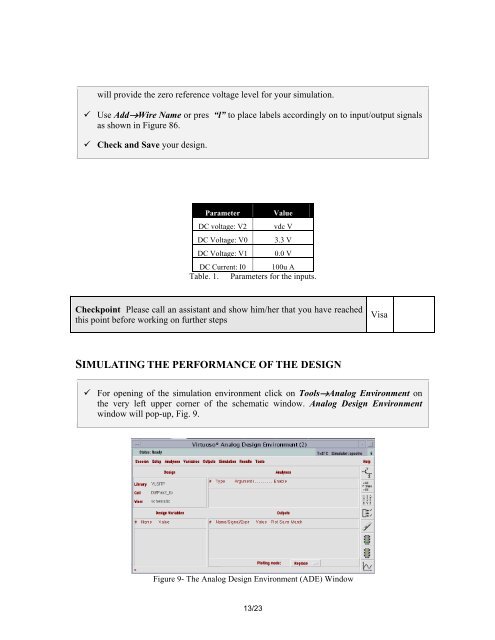
will provide the zero reference voltage level for your simulation. Use Add→Wire Name or pres “l” to place labels accordingly on to input/output signalsas shown in Figure 86. Check and Save your design.Parameter ValueDC voltage: V2 vdc VDC Voltage: V0 3.3 VDC Voltage: V1 0.0 VDC Current: I0 100u ATable. 1. Parameters for the inputs.Checkpoint Please call an assistant and show him/her that you have reachedthis point before working on further stepsVisaSIMULATING THE PERFORMANCE OF THE DESIGN For opening of the simulation environment click on Tools→<strong>Analog</strong> Environment onthe very left upper corner of the schematic window. <strong>Analog</strong> <strong>Design</strong> Environmentwindow will pop-up, Fig. 9.Figure 9- The <strong>Analog</strong> <strong>Design</strong> Environment (ADE) Window13/23


