
Create successful ePaper yourself
Turn your PDF publications into a flip-book with our unique Google optimized e-Paper software.
INTRODUCTION > TABLE OF CONTENTSTable of ContentsIntroduction ...........................................................................iAbout This <strong>Manual</strong> ................................................................... iGetting Started .....................................................................1Unit Overview .......................................................................... 1Charging the 276C Plus .......................................................... 2Information about Charge Mode .................................................... 2Turning On the 276C Plus ....................................................... 3Adjusting the Backlight and Volume .............................................. 3Getting Satellite Signals ......................................................... 4Viewing GPS Status with the GPS page ......................................... 4Receiver Status ............................................................................... 5GPS Options ................................................................................... 6GPS Tips ......................................................................................... 6Learning about the Keypad .................................................... 7Using the 276C Plus ................................................................ 8Understanding Features .................................................................. 8Selecting Options and Entering Data .............................................. 9Using the Databases ...................................................................... 10Simulated Basic Navigation ................................................. 11Activating Simulator Mode .......................................................... 11Entering a New Location .............................................................. 11Simulating Navigation .................................................................. 12What is the Difference Between the Modes? ...................... 14Powerboat Mode ........................................................................... 14Sailboat Mode ............................................................................... 14Automotive Mode ......................................................................... 14Off Road Mode ............................................................................. 14Which Mode Should I Use? .......................................................... 14How do I Switch Modes? ............................................................. 14Basic Operation .................................................................15Finding an Item ...................................................................... 15Using the Find From Feature ........................................................ 16Recently Found Items ................................................................... 16Viewing the Information Page ...................................................... 16Creating and Using Routes .................................................. 17Creating a Route ........................................................................... 17Navigating a Saved Route ............................................................ 18Editing a Route ............................................................................. 19Using the Route Tab Options ........................................................ 20<strong>Manual</strong>ly Transitioning to the Next Waypoint ............................. 20Creating and Using Waypoints ............................................ 21Marking Your Present Position ..................................................... 21Creating a Waypoint Using the Map ............................................. 22Creating a Waypoint by Entering Coordinates ............................. 23Going to a Waypoint ..................................................................... 23Reviewing a Waypoint .................................................................. 24ii276C Plus Owner’s <strong>Manual</strong>190-00501-00_0A.indd 21/13/2005 10:43:19 AM
INTRODUCTION > TABLE OF CONTENTSEditing a Waypoint ....................................................................... 25Adding a Waypoint to a Route ...................................................... 25Projecting a Waypoint ................................................................... 26Averaging the Waypoint’s Location ............................................. 27Organizing Waypoints into Categories ......................................... 27Deleting Waypoints ...................................................................... 29Proximity Points ........................................................................... 30Managing Your Tracks .......................................................... 32Setting up and Saving your Tracks ............................................... 32Saved Tracks ................................................................................. 34Navigating a Saved Track ............................................................. 35TracBack Tips ............................................................................... 35Basic Operation In the Sea Modes ..................................36Sea Modes Page Sequence .................................................. 36Navigating in the Sea Modes ................................................ 37Initiating Navigation ..................................................................... 37Man OverBoard (MOB) ............................................................... 39Adding Points to Your Route ........................................................ 39Following a Route in the Sea Modes ................................... 40Follow Your Route on the Map Page ............................................ 40View Your Heading with the Compass Page ................................ 40View Your Path on the Highway Page .......................................... 40See Your Progress on the Active Route Page .............................. 41Watch Your Trip Data on the Position Data Page ......................... 41Sea Modes Pages and Features .......................................42Map Page ................................................................................ 42Map Orientation ............................................................................ 42Zooming In and Out of the Map ................................................... 43Panning the Map ........................................................................... 44Changing the Map Detail .............................................................. 45Measuring Distance ...................................................................... 45Compass Page ....................................................................... 46Compass Page Options ................................................................. 46Using the <strong>Marine</strong> Timer ................................................................ 47Highway Page ........................................................................ 48Using the Highway Page .............................................................. 48Highway Page Options ................................................................. 49Active Route Page ................................................................. 50Active Route Page Options ........................................................... 50Tide Page ............................................................................... 51Position Data Page ................................................................ 53Position Data Page Options .......................................................... 53Entering Your Vessel’s Information ..................................... 54Setting Your Home Port ................................................................ 55Navigating to Your Home Port ..................................................... 55Viewing Your <strong>Marine</strong> Log ...................................................... 56276C Plus Owner’s <strong>Manual</strong>iii190-00501-00_0A.indd 31/13/2005 10:43:19 AM
INTRODUCTION > TABLE OF CONTENTSUsing DSC .............................................................................. 57Understanding Distress Calls ........................................................ 57Understanding Position Reports ................................................... 57Making a Distress Call ................................................................. 57Receiving a Position Report or Distress Call ............................... 58Navigating to a DSC Location ................................................ 58DSC Call List .......................................................................... 58DSC Log ................................................................................. 59DSC Directory ........................................................................ 59Setting up DSC ............................................................................. 60Basic Operation In the Land Modes ................................61Automotive Mode Page Sequence ....................................... 61Off Road Page Sequence ...................................................... 61Navigating in Automotive Mode ........................................... 62Initiating Navigation ..................................................................... 62Following a Saved Route .............................................................. 63Editing Your Route ....................................................................... 63Entering Custom Avoids ......................................................... 64Creating a Detour .................................................................... 64Adding and Editing Stops (Via Points) ................................... 65Following an Automotive Route ................................................... 66Track your Progress with the Map Page ................................. 66Watch your Trip Information .................................................. 66See your Next Turn with the Current Route Page ................... 66Navigating in Off Road Mode ............................................... 67Initiating Navigation ..................................................................... 67Following an Off Road Route ....................................................... 67See Your Route on the Map Page ............................................ 67View Your Heading with the Compass Page .......................... 67See Your Progress on the Active Route Page ......................... 67Watch your Trip Information .................................................. 67Pages and Features of the Land Modes ..........................68Map Page ................................................................................ 68Current Route Page ............................................................... 69Saving the Current Route ............................................................. 69Trip Computer Page .............................................................. 70Resetting the Trip Computer ......................................................... 70Dashboard Page .................................................................... 71Additional Features ...........................................................72Setting Alarms ....................................................................... 72Navigation (Nav) Alarms ............................................................. 72System Alarms .............................................................................. 73Sonar Alarms ................................................................................ 73Using the Calendar ................................................................ 74Day View ...................................................................................... 74Week View .................................................................................... 74Month View .................................................................................. 74Calendar Options .......................................................................... 74iv276C Plus Owner’s <strong>Manual</strong>190-00501-00_0A.indd 41/13/2005 10:43:19 AM
INTRODUCTION > TABLE OF CONTENTSViewing Celestial Information .............................................. 75Sun & Moon Tab .......................................................................... 75Hunt & Fish Tab ........................................................................... 76Viewing Messages ................................................................. 77Viewing the Temperature ...................................................... 78Changing the Temperature Display .............................................. 78Reset the Temperature Graph ....................................................... 78Customizing Your 276C Plus ............................................79Setting up the System ........................................................... 79Adding a Welcome Message ......................................................... 79Enabling Map Data ....................................................................... 80Changing the Page Layout and Data Fields .................................. 81Setting up the Map Page ............................................................... 81Changing the Page Sequence ........................................................ 82Some Tips about the Page Sequence ....................................... 82Changing the Display ................................................................... 83Changing the Sounds .................................................................... 84Changing the System Settings ...................................................... 85Setting the Timers ......................................................................... 86Changing the Time ........................................................................ 86Customizing the Units .................................................................. 87Restoring Defaults ........................................................................ 87Customizing the Routing and Guidance Settings .............. 88Road Routing Settings .................................................................. 88Guidance Settings ......................................................................... 89Changing the Location Settings .......................................... 90Changing the Location Format ..................................................... 90Selecting a Different Map Datum ................................................. 90Selecting a Different Heading Reference ..................................... 90Changing the Data Format ................................................... 91Advanced NMEA Output Setup ................................................... 93Setting up and Using Sonar .............................................94Using the Sonar Page ........................................................... 94Adjusting the Sonar Page ............................................................. 95Adjustment Options ................................................................ 96Resizing the Split Screen .............................................................. 97Using the Pointer on the Sonar Page ............................................ 98Marking an Underwater Waypoint ............................................... 98Showing Sonar on the Map Page .................................................. 99Setting Up the Sonar ........................................................... 100Calibrating the Water Speed ....................................................... 101Setting up the Sonar Display ...................................................... 102Understanding Sonar .......................................................... 103Understanding the Sonar Display ............................................... 103Transducer Coverage .................................................................. 104Whiteline .................................................................................... 105Thermoclines .............................................................................. 105276C Plus Owner’s <strong>Manual</strong>v190-00501-00_0A.indd 51/13/2005 10:43:20 AM
INTRODUCTION > TABLE OF CONTENTSAppendix ..........................................................................106Specifications ...................................................................... 106Physical ....................................................................................... 106Power .......................................................................................... 106Performance ................................................................................ 106Accuracy ............................................................................... 106Care Information ................................................................. 107Cleaning the Unit ........................................................................ 107Storing the 276C Plus ................................................................. 107Immersing the Unit in Water ...................................................... 107Optional Accessories .......................................................... 108Installation Information ....................................................... 109Connecting the Power/Data Cable .............................................. 109Connecting Your 276C Plus to a Computer ................................ 110Information about USB Drivers ............................................ 110Using xImage for Customized Waypoint Icons .......................... 111Installing and Removing Data Cards .......................................... 111Interfacing ................................................................................... 112Removing the Antenna ............................................................... 112Learning about GPS ............................................................ 113Common GPS Terms .................................................................. 113What is Differential GPS (DGPS)? ............................................ 113Differential Field ........................................................................ 113What is WAAS? .......................................................................... 114LORAN TD Setup ................................................................. 115LORAN TD Feature ................................................................... 115Using the LORAN TD Format ................................................... 115Map Datums and Location Formats .................................. 117What are a Map Datum and which should I use? ....................... 117What is a Location Format and which should I use? .................. 117Digital Selective Calling (DSC) ........................................... 118What is a Maritime Mobile Service Identity (MMSI) number? . 118How are MMSI assignments obtained? ...................................... 119Non-Federal Users in the United States ............................... 119Federal Users in the United States ....................................... 119Users Outside the United States ............................................ 119Users In Canada .................................................................... 119How can Garmin help you with DSC? ....................................... 119Data Field Options ............................................................... 120Messages ............................................................................. 122Safety and Product Information ......................................... 123Software License Agreement ...................................................... 123Product Registration ................................................................... 123Contact Garmin ........................................................................... 123Limited Warranty ........................................................................ 124FCC Compliance ........................................................................ 125Safety Information ...................................................................... 125Index .................................................................................127vi276C Plus Owner’s <strong>Manual</strong>190-00501-00_0A.indd 61/13/2005 10:43:20 AM
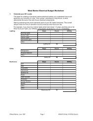
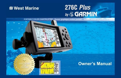
GETTING STARTED > UNIT OVERVIEWGETTING STARTEDUnit OverviewThe 276C Plus is an all-in-one, versatile color chartplotter and automobile navigator—perfect for land or water. This portable GPS navigatorfeatures a 256-color TFT display that is easy to read in bright sunlight, a built-in basemap, and auto routing to provide you with automaticallygenerated turn-by-turn directions.256-Color TFT displaywith backlightingAntennaDetachable antennacollapses for storage.Be sure the antenna isup (as shown here)to receive satellitesignals. Refer tothe Appendix,page 112, forinstructions onremoving theantenna.Battery pack. Press tab down toremove battery pack for replacement,if necessary. See the “SafetyInformation” on page 125 for moreinformation about the lithium-ionbattery pack.External powerBacklit keypad for easy nighttime operationconnector under USB connectorSerial numberweather cap under weather cap Slot for optional data card276C Plus Owner’s <strong>Manual</strong> 1190-00501-00_0A.indd 11/13/2005 10:43:23 AM
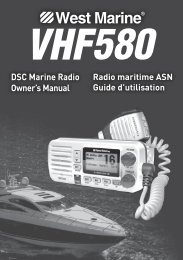
GETTING STARTED > CHARGING THE 276C PLUSCharging the 276C PlusBefore using the unit, you may need to charge the battery in the276C Plus. Simply plug the unit into an external power source tocharge. You can use the unit while it is charging.To charge the unit’s battery:1. Lift the rubber weather cap to expose the power connectoron the back of the unit. Refer to the image on page 1 forconnector location.2. Align the notches and push the plug into the connector untilfully seated.3. Plug the 12 Volt adapter into an available AC outlet, orcigarette lighter receptacle if you have a Cigarette LighterAdapter. Use care when routing the cable; be certain that itdoes not interfere with vehicle operation.The unit begins charging as soon as external power is applied.Placing the unit in Charge mode, as discussed below, charges theunit more quickly than when the unit is turned on and reduces drawon the vessel/vehicle battery.Information about Charge ModeApplying external power to the 276C Plus automatically turns onthe unit for full operation. If the battery is present and needs to becharged, the external power source charges the battery while the unitis in use.If you do not want to use the unit, but you would like to charge thebattery, you can put the unit into Charge mode. Connect the unitto an external power supply. Press and hold the red POWER key.Instead of completely turning off, the unit now goes into Chargemode, as shown below.Charge ModeNOTE: While in Charge mode, the unit draws a small amount ofcurrent from the vessel/vehicle battery. To avoid discharging thevehicle’s battery, disconnect the external power cable from the276C Plus when not in use for several days.After using the unit extensively, you may notice that the lithiumionbattery is not holding a charge any more. This is common forlithium-ion batteries. Contact Garmin or your Garmin Dealer toorder a Battery Pack replacement if you are experiencing chargingissues with your battery.2 276C Plus Owner’s <strong>Manual</strong>190-00501-00_0A.indd 21/13/2005 10:43:23 AM
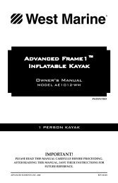
GETTING STARTED > GETTING SATELLITE SIGNALSGetting Satellite SignalsAfter you turn on the 276C Plus, the unit automatically beginssearching for satellites. The GPS page is displayed while the unitis gathering satellite signals and acquiring a fix, which should takeonly a few minutes. While the 276C Plus is gathering satellitesignals, the GPS page displays the status as “Acquiring Satellites.”It may take a few minutes to acquire satellites and display yourcurrent location on the map. Be patient as the unit acquires satellitedata. To get signals more quickly, be sure the antenna is raised to theup position shown in the image on page 1.GPS PageNOTE: While acquiring satellites, the Map page may display thewrong location, such as China. This does not mean your unit hasthe wrong data loaded; it simply means you need to wait a fewmore minutes to acquire satellites and find your current location.Viewing GPS Status with the GPS pageThe GPS page provides a visual reference of satellite acquisition,receiver status, accuracy, as well as other system information.The sky view and signal strength bars give an indication of whatsatellites are visible to the receiver and whether they are beingtracked.As the receiver locks onto satellites, a signal strength bar appearsfor each satellite in view, with the appropriate satellite numberunderneath each bar. The numbers displayed below each barrepresent the particular satellite that is being received. Numbersabove 33 indicate WAAS satellites.The sky view shows a birds-eye view of the position of each satelliterelative to the receiver’s last known position. The outer circlerepresents the horizon (north up), the inner circle represents 45ºabove the horizon, and the center point represents a position directlyoverhead. You can also set the sky view to a Track Up configuration,causing the top of the sky view to align along your current trackheading. Press MENU to change the configuration of the sky view.A power source indicator shows the unit is operating off batterypower ( ), that the unit is charging ( ), or that anexternal power source is in use ( ).4 276C Plus Owner’s <strong>Manual</strong>190-00501-00_0A.indd 41/13/2005 10:43:24 AM
GETTING STARTED > GETTING SATELLITE SIGNALSSignalReceiver • Searching the Sky—the receiver is looking for satellites.StrengthStatus• AutoLocate—the receiver is looking for any satellite whoseBarsFieldalmanac has been collected, which can take up to 5 minutes.Sky view• Acquiring Satellites—the receiver is looking for andPowercollecting data from satellites visible at its last known orSourceIndicatorinitialized position, but has not acquired a fix.• 2D GPS Location: At least three satellites have beenGPS PageThe progress of satellite acquisition is shown in three stages:• No signal strength bars—the receiver is looking for thesatellites indicated.• White signal strength bars—the receiver has found thesatellite and is collecting data.acquired, and a two-dimensional position fix has beencalculated. “2D Differential” appears when you are receivingDGPS corrections in 2D mode, and a “D” appears on thestrength bar of satellites being corrected.• 3D GPS Location: At least four satellites have beenacquired, and a three-dimensional fix has been calculated.“3D Differential” appears when you are receiving DGPS• Green signal strength bars—the receiver has collected thecorrections in 3D mode, and a “D” appears on the strength barnecessary data from this satellite.of satellites being corrected.As soon as the 276C Plus has collected the necessary data from the • Lost Satellite Reception—the receiver is no longer trackingbest satellites in view to calculate a fix, the status field indicates the enough satellites for a 2D or 3D fix.status of the receiver. The unit then updates the position, date andtime.• Receiver Not Usable—the receiver is unusable, possibly dueto interference or abnormal satellite conditions. Turn the unitoff and back on to reset.Receiver Status• Simulating GPS—the receiver is in simulator mode.The Receiver Status field displays one of the following conditions:• GPS Off—the GPS receiver is turned off.276C Plus Owner’s <strong>Manual</strong> 5190-00501-00_0A.indd 51/13/2005 10:43:24 AM
GETTING STARTED > GETTING SATELLITE SIGNALSGPS OptionsPress MENU two times to open the Main Menu. Use the Rockerkey to highlight GPS. Press MENU to open the options menu.GPS Page Options MenuStart/Stop Simulator—activates and deactivates simulator mode,which is particularly helpful when learning how to use your unit.WAAS On—enables WAAS capability. Refer to page 114 of the“Appendix” for more information about WAAS.Track/North Up—orients the sky view display on the GPS page tonorth up or track up.New Altitude—allows you to manually enter your altitude.New Location—allows you to enter a new location automatically orusing the map.GPS TipsWhile the receiver is gathering information, your location onthe map may display as different from where you actually arelocated. Be patient. As soon as the receiver gathers enough satelliteinformation, your proper location is displayed on the map.Any time you have traveled more than 600 miles with the GPSreceiver turned off, the receiver may take longer than normal toinitialize and find your location.The GPS receiver can lose satellite signals due to interference fromsuch items as buildings, tunnels, and heavy tree cover. Monitoringthe GPS status is recommended.To learn about GPS, refer to “Learning about GPS” on page 113.6 276C Plus Owner’s <strong>Manual</strong>190-00501-00_0A.indd 61/13/2005 10:43:24 AM
Learning about the KeypadPress the IN key to adjust the map scale to show a smallerarea with more detail (zoom in).Press the OUT key to adjust the map scale to show a largerarea with less detail (zoom out).Press the PAGE/MODE key to cycle through the mainpages in sequence and exit a submenu page. Press and holdto switch between the usage modes.Press QUIT to cycle the unit through the main pages inreverse sequence, revert to the previous value in a dataentry field, or cancel an unintended function.Press ENTER to select a highlighted option. Whenentering data, it allows you to initiate entry and to acceptthe selected value. Press and hold for more than onesecond to mark your current location as a waypoint.Press MENU to display a menu of available options forthe current page. Press MENU twice to display the MainMenu.GETTING STARTED > LEARNING ABOUT THE KEYPADPress the NAV/ MOB ( Navigate/Man OverBoard) keyto display the Navigation Menu. While in the sea modes,press and hold for more than one second to activate theMan Overboard (MOB) function.While navigating to a destination in a land mode, pressand hold to display the Next Turn page and announce thenext turn when using the external speaker. If you are notnavigating to a destination but are in a land mode, pressand hold NAV/MOB to announce the GPS status over theexternal speaker.Press the FIND key to quickly search for and access userwaypoints, cities, points of interest, services, and otheritems used for navigation.Press and hold the POWER key for more than one secondto turn the unit on and off. Briefly press and release toadjust the backlighting and external speaker volume.Use the Rocker key to highlight options and to enterdata. Also use to pan the arrow on the Map page.276C Plus Owner’s <strong>Manual</strong> 7190-00501-00_0A.indd 71/13/2005 10:43:25 AM
GETTING STARTED > USING THE 276C PLUSUsing the 276C PlusThis section explains how to enter and select information with the276C Plus.Understanding FeaturesThe 276C Plus advanced keypad system is designed to allow quick,convenient selection of navigation options and data entry. As youprogress through this Owner’s <strong>Manual</strong>, you will be directed topress a specific key or highlight a field on the screen. When youare directed to press a key, you should press and quickly release thekey. If the key needs to be held down for a period of time to activatea secondary function, the instructions will tell you to do so. Whena field is selected on the screen, it is highlighted in yellow. Theposition of the highlight is controlled by the Rocker key.The following terms are used throughout this manual:Highlight—move the highlighted area on the screen Up, Down,Left, or Right with the Rocker key to select individual fields.Moving the highlight to a given location allows you to make aselection, begin data entry, or scroll through a list.Field—the location on a page where data or an option may beentered and displayed. Select (highlight) a field using the Rockerkey to begin entering data or selecting options.On-Screen Button—similar to “field.” Use the Rocker key tohighlight a button and press ENTER to select the button.Scroll Bar—when viewing a list of items too long to display onthe screen, a scroll bar appears along the right side of the list.The position of the scroll bar indicates which portion of the list iscurrently displayed. To scroll through a list, press Up or Down onthe Rocker key.Default—the factory setting saved in the unit’s memory. You canchange the settings as you like, but you can also revert to the factory(default) settings when you select Restore Defaults.Highlighted FieldOn-screen buttonsField8 276C Plus Owner’s <strong>Manual</strong>190-00501-00_0A.indd 81/13/2005 10:43:26 AM
GETTING STARTED > USING THE 276C PLUSSelecting Options and Entering DataTo enter data and select options, use the Rocker key to highlight,select, or choose an item in a list or a field on the screen. Use theENTER key and the Rocker key to select options, enter names andnumbers in data fields, and activate your selections.To select and activate an option:1. With any page displayed, press MENU. An options menuappears with a list of optional features for that page.2. Use the Rocker key to move the highlight Up, Down, Right,or Left on the menu to your desired selection.3. Press ENTER to activate the feature. Another window maythen appear with more options. If so, select the desiredoption and press ENTER again.To exit a menu or return to the previous setting:Press QUIT. The QUIT key moves backwards through yoursteps. Press QUIT repeatedly to return to the starting page.To select and activate an on-screen button:1. On a page with on-screen buttons, use the Rocker key tohighlight the desired on-screen button.2. Press ENTER.On-Screen ButtonTo practice entering data, try marking a waypoint and customizingone of the waypoint properties, such as the waypoint name.Selecting an option from an options menuTo mark your current location as a waypoint, press and holdENTER/MARK until the New Waypoint page appears.276C Plus Owner’s <strong>Manual</strong> 9190-00501-00_0A.indd 91/13/2005 10:43:26 AM
GETTING STARTED > USING THE 276C PLUSTo enter data in a data field:1. Use the Rocker key to highlight the desired data field andpress ENTER to activate the field.2. Press Up or Down on the Rocker key to select characters.Press Right to move to the next character or press Left tomove back to the previous character. If there are two lines ofdata, keep pressing Right to drop to the next line.3. After entering the desired data, press ENTER.Using the DatabasesOptional Garmin Data Cards and MapSource CD-ROMs enhancethe versatility of your 276C Plus. With optional MapSource CitySelect data, you can view listings of nearby restaurants, lodging,shopping centers, attractions and entertainment, and even retrieveaddresses and phone numbers for any listed location.The included USB Interface Cable or an optional PC Interface Cable(with a serial connector) is used to transfer MapSource CD-ROMdata to the optional Data Card.Refer to the Garmin Web site at http://www.garmin.com/cartography/ for compatible MapSource products.Entering dataTIP: To clear the entire data field, highlight the left-mostcharacter field and press Left once more on the Rocker key.Not all fields are programmable. When you are on a page with fieldsthat are not selectable, the highlight skips over them.10 276C Plus Owner’s <strong>Manual</strong>190-00501-00_0A.indd 101/13/2005 10:43:26 AM
Simulated Basic NavigationTo help you get to know your 276C Plus, you can use the unit inSimulator mode. Simulator mode is also helpful for practicingwith the unit indoors or when no satellite signals are available. Allwaypoints and routes created in Simulator mode are retained inmemory for future use. The following section describes how to usesimulator mode and walks you through some basic navigation usingthe simulator.Activating Simulator ModeYou can activate Simulator mode from the GPS page.To put activate Simulator mode using the GPS page:1. Press PAGE or QUIT to display the GPS page.2. Press MENU to open the GPS page options menu.3. Highlight Start Simulator and press ENTER.NOTE: Do not attempt to navigate using Simulator mode. Whenthe unit is set to Simulator mode, the GPS receiver is turned off.Any Satellite Signal Strength Bars displayed are only simulationsand do not represent the strength of actual satellite signals.GETTING STARTED > SIMULATED BASIC NAVIGATIONHighlight Start Simulator and press ENTER.Entering a New LocationFrom the GPS options menu you can also enter a New Location tosimulate from.To enter a New Location using the map:1. Press PAGE or QUIT to display the GPS page.2. Press MENU to open the GPS page options menu.3. Highlight New Location and press ENTER.4. Highlight Use Map and press ENTER.5. Use the Rocker key to move the panning arrow to thedesired location on the map and press ENTER.276C Plus Owner’s <strong>Manual</strong> 11190-00501-00_0A.indd 111/13/2005 10:43:27 AM
GETTING STARTED > SIMULATED BASIC NAVIGATIONSimulating NavigationThe main purpose of using a GPS receiver is for navigating to aknown position. To get a feel for navigating with the 276C Plus, itis a good idea to practice navigation in Simulator mode. For thissimulation we have set our location to the San Diego coast.To find a marine destination:1. Be sure the 276C Plus is set to Simulator mode (see“Activating Simulator Mode” on the previous page).2. Press the FIND key.3. Highlight Tide Stations and press ENTER.4. Use the Rocker key to select a nearby Tide Station andpress ENTER. For our example, we selected Point Loma.5. With Go To highlighted on the Tide Station Information Page,press ENTER.To simulate navigation to the marine destination:1. Follow the previous steps to find a destination. The 276CPlus switches to the Map page. A magenta line shows thedirect route from your current location to your destination. Ifdesired, press IN or OUT to adjust the zoom level.2. Press the PAGE key twice to display the Compass page.3. Press Up on the Rocker key to increase the speed to 40 kt.(which is the desired speed setting). Press the Rocker keyRight or Left to simulate steering.4. Press QUIT twice to return to the Map Page. Press IN toadjust the zoom level. Observe the movement of the positionmarker (triangle) as the unit simulates navigation.5. If desired, press PAGE or QUIT to view the simulatednavigation on the other main pages.Simulated navigation displayed on the Map Page12 276C Plus Owner’s <strong>Manual</strong>190-00501-00_0A.indd 121/13/2005 10:43:27 AM
BASIC OPERATION > FINDING AN ITEMUsing the Find From FeatureThe Find option also supports a “find from” feature that allows youto center your search around an item that you have just found. Forexample, suppose you search for Anchorage, and the search showsa “Recommended Anchorage” search result. If you press FINDagain, you will see “From Recommended Anchorage” as the newsearch from point.There are several ways to find an item from another item:• Use the map to highlight a point and press the FIND key.• Locate an item using the Find Menu then press FIND again.• Open the Find Menu and press MENU to select from one ofthe Find Menu options.Find From Options MenuRecently Found ItemsThe Recently Found page displays a list of the items you havesearched for or gone to recently.To view recently found items:1. Press the FIND key. The Find Menu opens.2. Use the Rocker key to highlight Recently Found. PressENTER. The Recently Found page opens.Viewing the Information PageEach item on the map and each item listed in the Find Menu resultslist has an information page.To view details about an item:1. Highlight the desired point on the map or in the searchresults list and press ENTER.An Information page appears with details about the item ina tabbed format. Depending on the type of item, additionaloptions are available, such as viewing the item on the Map,viewing a tide chart, viewing the list of maps on your datacard, and viewing the next item in the search results list.2. Press PAGE or QUIT to exit the information page. You canalso highlight one of the on-screen buttons and press ENTERto perform that operation.16 276C Plus Owner’s <strong>Manual</strong>190-00501-00_0A.indd 161/13/2005 10:43:28 AM
Creating and Using RoutesYou can create and store up to 50 reversible routes, with up to 300points each.Creating a RouteRoutes can be created a few different ways using the Route tabof the Main Menu. One way is to select waypoints from the FindMenu, allowing you to see a list of the route points as you create theroute. Another way is by selecting waypoints or map items from theMap page, allowing you to see each route point graphically onscreenas you create the route.Once you start navigating a route, it is saved to the 276C Plus unit’smemory. You can view the saved routes at any time using the Routetab of the Main Menu.The Route tab displays all of the saved routes in the 276C Plusmemory. If a route has a small automobile icon in front of it, itis a turn-by-turn route created in Automotive mode.NOTE: You must manually save an Automotive mode route; it isnot saved automatically.BASIC OPERATION > CREATING AND USING ROUTESTo create a route using the Find Menu:1. Press MENU twice to display the Main Menu.2. Use the Rocker key to highlight the Route tab.3. Press MENU to display the Route options menu. Select NewRoute and press ENTER. Or, highlight the first availableblank route slot and press ENTER.4. The Route Review page automatically opens, displaying ablank route. Press ENTER to find items to add to the route.5. The Find Menu opens. Using the methods discussed in the“Finding an Item” section beginning on page 15, select apoint to add to your route. When you find an item, highlightOK and press ENTER to add the point to the route. Repeatuntil you have added all of the points to the route.Creating a new route on Route Review page276C Plus Owner’s <strong>Manual</strong> 17190-00501-00_0A.indd 171/13/2005 10:43:29 AM
BASIC OPERATION > CREATING AND USING ROUTESTo create a route graphically:1. Press MENU twice to display the Main Menu. Use theRocker key to highlight the Route tab.2. Press MENU to display the Route options menu. Select NewRoute and press ENTER.3. Highlight the first blank slot in the Route List page and pressMENU. Use the Rocker key to highlight Edit on Map andpress ENTER.4. Use the Rocker key to highlight the location you want to addand press ENTER.5. If you have selected an area of the map that is not a featureor waypoint, a new waypoint is created for that location.Press ENTER on the New Waypoint page to save thelocation as a waypoint and continue adding points to yourroute. Repeat until you have added all points to the route.6. When finished, press QUIT twice to return to the RouteReview page. Or, press MENU, highlight Edit as Text, andpress ENTER to view the Route Review page.Navigating a Saved RouteThe Navigate Route option allows you to easily select and activate asaved route.To navigate a saved route:1. Press the NAV key.2. Use the Rocker key to highlight Navigate Route and pressENTER.3. Highlight the desired route and press ENTER.Select desiredroute from listSelect the route you want to take.Creating a new route on the map18 276C Plus Owner’s <strong>Manual</strong>190-00501-00_0A.indd 181/13/2005 10:43:29 AM
Editing a RouteOnce you have created a route, the Route Review page allows you toedit a route and review route points of a selected route.To change the name of the route:1. Press MENU twice to open the Main Menu. Highlight theRoute tab.2. Use the Rocker key to highlight the name of the desiredroute and press ENTER.3. With the Route Review page displayed, use the Rocker keyto highlight the route name field at the top of the page andpress ENTER.Enter a newRoute namehereRoute Review Page4. Use the Rocker key to enter the desired route name. Thenpress ENTER.To add points to the route:1. Press MENU twice to open the Main Menu. Use the Rockerkey to select the Route tab.2. Use the Rocker key to select the desired route and pressENTER.3. Use the Rocker key to highlight the place in the route whereyou want to add the new point. The new point will be addedbefore the highlighted route point. Press MENU.4. Highlight Insert Waypoint and press ENTER. The FindMenu automatically opens for you to search for and selectthe point you want to add to the route.5. In the Point Review page, highlight OK and press ENTER toadd the new point to the route.To edit the route on the map:1. Press MENU twice to open the Main Menu. Use the Rockerkey to select the Route tab from the vertical menu of tabs.2. Select the desired route and press ENTER. Press MENU toopen the Route Review page options menu.3. Highlight Edit on Map and press ENTER.4. Select the route and press ENTER.BASIC OPERATION > CREATING AND USING ROUTES5. Drag the route to the new location and press ENTER.6. On the New Waypoint page, highlight OK, and press ENTER.7. Repeat steps 4 through 6 until all desired points are added tothe route. Press Quit when finished.276C Plus Owner’s <strong>Manual</strong> 19190-00501-00_0A.indd 191/13/2005 10:43:29 AM
BASIC OPERATION > CREATING AND USING ROUTESTo plan your route:1. Press MENU twice to open the Main Menu. Use the Rockerkey to select the Route tab.2. Highlight the desired route and press ENTER.3. Press MENU.4. Highlight Plan Route and press ENTER.Using the Route Tab OptionsThe Route tab in the Main Menu displays all the routes currentlystored in memory, along with a descriptive name for each route.Highlight a route and press MENU to open the options menu. Fromhere you can activate the route, copy it, delete it, delete all routes,and create a new route. You can also set up the routes to manuallytransition to the next waypoint.Enter your estimated Speed and Fuel Flow for trip planning.5. Enter the desired data for Speed and Fuel Flow. You alsocan enter the date and time of your departure. Press QUIT toreturn to the Route Review page.NOTE: Fuel flow rates are measured in “units per hour.”System setting changes for units of measure (statute, nautical, ormetric) do not affect the fuel flow measure. You should enter fuelflow rates based upon information for your vessel (such as theoperator’s manual or performance specifications) and make noteof the desired units of measure (gallons or liters).<strong>Manual</strong>ly Transitioning to the Next WaypointFrom the Route tab options menu, highlight Set Up Routes andpress ENTER to set the route leg transition (or waypoint transition).Select Distance to enter a radius so that when you are within theentered distance, the 276C Plus will direct you to the next point onyour route.When you select <strong>Manual</strong>, you can choose when you want totransition to the next waypoint while navigating a route. While youare navigating the route, open the Active Route page. Press MENU.Highlight Next Route Waypoint and press ENTER to have the276C Plus start routing you to the next point in your route.20 276C Plus Owner’s <strong>Manual</strong>190-00501-00_0A.indd 201/13/2005 10:43:30 AM
BASIC OPERATION > CREATING AND USING WAYPOINTSCreating and Using WaypointsWaypoints are locations or landmarks you record and store in your276C Plus. They are locations you may later want to return to, suchas checkpoints on a route or other features. You can add waypointsto routes and even create a Go To directly to the selected waypoint.Save your current location as a waypoint by pressing and holdingENTER/MARK. You can find waypoints using the map or the FindMenu and then store them in the unit before ever leaving home.The 276C Plus can store up to 3000 alphanumeric waypoints with auser-defined icon, comment, altitude, depth, and temperature. Youcan create a waypoint using three basic methods:Marking Your Present PositionUse the ENTER/MARK key to quickly create a new waypoint atyour current location. You must have a valid position (2D or 3D) fixto mark your present position. You can determine the satellite fix bylooking at the GPS page.To mark your present position:1. Press and hold the ENTER/MARK key until the NewWaypoint page appears, then release it. A default four-digitname and symbol are assigned for the new waypoint.• ENTER/MARK—allows you to quickly mark your presentposition.• Graphically—allows you to define a new waypoint positionfrom the map display using the Rocker key.• Text Entry—allows you to enter a new waypoint’s positionNew Waypoint Pagecoordinates manually.2. To accept the waypoint with the default information, use theRocker key to highlight OK and press ENTER.3. To change any information on the New Waypoint page,highlight the appropriate field and press ENTER. Afterentering and confirming your changes, highlight OK andpress ENTER.276C Plus Owner’s <strong>Manual</strong> 21190-00501-00_0A.indd 211/13/2005 10:43:30 AM
BASIC OPERATION > CREATING AND USING WAYPOINTSCreating a Waypoint Using the MapYou can quickly create a waypoint using the Map page. When youpan the map and move the arrow over a map item, you will see ahighlighted description of that item. The 276C Plus uses the mapitem text shown on the map as the default name and symbol for thenew waypoint.To create a new waypoint using the Map page:1. Press PAGE or QUIT until the Map page is displayed.2. Use the Rocker key to move the arrow to the desired mapposition or map feature.3. Press and quickly release ENTER/MARK to capture thearrow position. Pressing and holding ENTER/MARK marksyour present position, not the arrow’s location.4. If you have highlighted a map feature, an information pageappears after you press ENTER. Use the Rocker key tohighlight Save and press ENTER to save the item as awaypoint.Map Feature Information PageSelect Save to save feature as a waypoint.5. The New Map Waypoint page appears. To accept thewaypoint with the default information, highlight OK and pressENTER.6. To change any information on the New Map Waypoint page,highlight the appropriate field and press ENTER. Afterentering your changes, highlight OK and press ENTER.22 276C Plus Owner’s <strong>Manual</strong>190-00501-00_0A.indd 221/13/2005 10:43:30 AM
BASIC OPERATION > CREATING AND USING WAYPOINTSCreating a Waypoint by Entering CoordinatesYou can manually enter location coordinates to create a waypoint.This method can be useful for creating a waypoint at a specificlatitude/longitude position from a chart.To create a new waypoint by entering locationcoordinates:1. Press ENTER/MARK to create a waypoint (or use yourfavorite method discussed in previous sections). The newwaypoint is created with the next available waypoint numberand the receiver’s last know position as the default position.2. On the New Waypoint page, use the Rocker key to highlightthe Location field and press ENTER. Use the Rocker keyto enter the desired position coordinates and press ENTERwhen finished.3. To change any of the other information on the New Waypointpage, highlight the appropriate field and press ENTER. Afterentering your changes, highlight OK and press ENTER.To change the location of a waypoint, highlight the character you wantto change in the Location field. Press Up or Down on the Rocker key tochange the character. Repeat until the new location is entered.Going to a WaypointYou can initiate a Go To to a Waypoint through the Find Menu orthrough the User Points tab in the Main Menu.To activate a Go To from the User Points tab:1. Press MENU twice to open the Main Menu.2. Select Points from the Main Menu, then highlight User.3. Highlight the desired waypoint in the list.4. Press NAV to open the Navigate Menu. Highlight Go To and press ENTER.276C Plus Owner’s <strong>Manual</strong> 23190-00501-00_0A.indd 231/13/2005 10:43:31 AM
BASIC OPERATION > CREATING AND USING WAYPOINTSReviewing a WaypointOnce you have created and stored a waypoint, you can modify,review, rename, move, or delete it at any time through the WaypointReview and Waypoint Edit Pages. For practical purposes, we willrefer to these pages as the “Waypoint pages,” unless it is necessaryto discuss them individually.To access the Waypoint Review page:1. Use the Rocker key to highlight the desired waypoint on theMap page. You can also press FIND, select Waypoints, andpress ENTER on the waypoint you want to review.2. Press ENTER to display the Waypoint Review page. If thewaypoint is located on a map feature or MapSource orBlueChart feature, the Waypoint Review page may includeadditional tabs containing information about the otherfeatures at that location.To access the Waypoint Edit page:1. Press MENU twice to view the Main Menu.2. Use the Rocker key to highlight Points from the vertical listof tabs, then highlight the desired waypoint from the list.Points Tab in the Main Menu3. Press ENTER to display the Waypoint Edit page.If the waypoint is located on a map feature or MapSource orBlueChart feature, the Waypoint Edit page will NOT displaythe details of the other map features.Use either of these methods to access the Waypoint page so you canedit the waypoint. Press MENU when the Waypoint page is open toaccess the Waypoint options menu.Waypoint Review Page24 276C Plus Owner’s <strong>Manual</strong>190-00501-00_0A.indd 241/13/2005 10:43:31 AM
BASIC OPERATION > CREATING AND USING WAYPOINTSEditing a WaypointYou can edit a waypoint from either the Points page of the MainMenu or the Waypoints category in the Find Menu.To edit the waypoint:1. Open the Waypoint page.2. Highlight the waypoint name, symbol, or another field youwant to change and press ENTER.Adding a Waypoint to a RouteYou can add the selected waypoint to the end of a route using theAppend to Route feature. This option is displayed when you arenot navigating. When you are navigating to a destination, Add toCurrent Route is displayed. The selected waypoint is added to thecurrent route before the route destination.To add a waypoint to the end of the route:1. Open the Waypoint page using one of the methods describedon the previous page. Press MENU.Symbol fieldName fieldWaypoint Page3. Use the Rocker key to select the desired symbol or to enterdata and press ENTER when done.To edit the next waypoint in the list:1. After you have edited the waypoint on the Waypoint Editpage (shown above), highlight Next and press ENTER.2. The Waypoint list is displayed with the next waypointhighlighted. Press ENTER to edit that waypoint.Waypoint Options Menu2. Highlight Append To Route or Add to Current Route andpress ENTER. The Select Route window appears.3. Highlight the desired route or select New Route, and thenpress ENTER.4. With OK highlighted, press ENTER to save the waypoint.276C Plus Owner’s <strong>Manual</strong> 25190-00501-00_0A.indd 251/13/2005 10:43:32 AM
BASIC OPERATION > CREATING AND USING WAYPOINTSProjecting a WaypointYou can also create a new waypoint by “projecting” the distance andbearing from a specific location to a new location.To create a new waypoint by projecting its location:1. Create a waypoint using your favorite method (discussed inprevious sections). The new waypoint is created with the nextavailable waypoint number and the receiver’s last knownposition as the default position.2. Press MENU twice to open the Main Menu.3. Highlight Points from the vertical list of tabs using theRocker key.4. Press MENU to open the New Waypoint page options menu.5. Highlight Project Location and press ENTER.6. To change the location from which you are projecting the newwaypoint, highlight the From field and press ENTER. TheFind Menu opens.Select the point that you will project your new waypoint fromjust as you would select a waypoint or point of interest. Formore information, see the “Finding an Item” section.7. To adjust the distance that the new waypoint will be projectedbeyond the original waypoint, highlight the Distance fieldand press ENTER. Enter the projection distance and pressENTER.8. To adjust the bearing that the new waypoint will be projectedfrom the original waypoint, highlight the Bearing field andpress ENTER. Enter the bearing and press ENTER.9. When you have adjusted all elements of the projectedlocation, highlight Save and press ENTER.10. Make any other desired changes to the new waypoint data(such as the name or symbol), then highlight OK and pressENTER.Project Location MenuEnter the location to project the waypoint from. Then enter thedistance and bearing to project the waypoint.26 276C Plus Owner’s <strong>Manual</strong>190-00501-00_0A.indd 261/13/2005 10:43:32 AM
BASIC OPERATION > CREATING AND USING WAYPOINTSDeleting WaypointsYou can delete waypoints from the waypoint list in the Points tab orfrom the Waypoint pages. To delete a waypoint from the Waypointpage, use the Rocker key to highlight the on-screen Delete buttonand press ENTER.NOTE: Once a waypoint is deleted from the list, it cannot berecovered from the unit. Back up important waypoints to acomputer using the optional PC cable and interface software,such as MapSource, or write them down by hand.To delete a waypoint from the User Points tab:1. From the User Points tab, use the Rocker key to highlightthe waypoint you want to delete.2. Press MENU, highlight Delete Waypoint, and press ENTER.3. Press ENTER to confirm.You can delete waypoints using a variety of methods.Press MENU to open the User Points options menu.To delete waypoints by symbol or category:1. From the User Points tab, highlight the waypoint you want todelete and press MENU.2. Highlight Delete by Symbol or Delete by Category andpress ENTER.3. When deleting by symbol, highlight the symbol of thewaypoint you want to delete and press ENTER. Whendeleting by category, select the category you want to deletefrom the list and press ENTER.4. Highlight OK and press ENTER to confirm. Choose Cancelor press QUIT to exit without deleting.276C Plus Owner’s <strong>Manual</strong> 29190-00501-00_0A.indd 291/13/2005 10:43:33 AM
BASIC OPERATION > CREATING AND USING WAYPOINTSTo delete waypoints by distance:1. From the User Points tab, highlight the waypoint to bedeleted and press MENU.2. Highlight Delete By Distance and press ENTER.3. Select Less Than or More Than and enter the desireddistance using the Rocker key.Proximity PointsYou can define an alarm circle around a stored waypoint position.The alarm circle can help you avoid reefs, rocks, or restrictedwaters. You can add proximity alarms to up to ten waypoints.Press MENU twice to open the Main Menu. Use the Rocker key tohighlight Points from the vertical list. Then press the Rocker key tothe right to highlight the Proximity tab.4. If desired, you can select a waypoint or point of interestas the From location. Highlight the From field and pressENTER. From the Find Menu, select the desired location andpress ENTER. When OK is highlighted, press ENTER.5. Highlight Delete and press ENTER to delete all waypointswithin the set location. Choose Cancel or press QUIT to exitwithout deleting the waypoints.Proximity Points TabIf a proximity alarm circle overlaps an existing alarm circle, a“Proximity Overlaps Another Proximity Waypoint” messageappears. Because the unit only alerts for one of the overlap points,use caution when navigating in these areas. If you enter an alarmcircle overlap, you are only alerted to the closest proximitywaypoint.30 276C Plus Owner’s <strong>Manual</strong>190-00501-00_0A.indd 301/13/2005 10:43:34 AM
BASIC OPERATION > CREATING AND USING WAYPOINTSTo add a proximity waypoint:1. Press MENU twice to open the Main Menu.2. Highlight Points from the vertical list of tabs. HighlightProximity from the row of tabs along the top of the screen.3. Use the Rocker key to highlight an empty line on theProximity List and press ENTER. The Find Menu appears.4. Select the desired waypoint or point of interest from the FindMenu. With OK highlighted, press ENTER to select thatpoint. (For complete information about selecting waypoints orpoints of interest from the Find Menu, see “Finding an Item”on page 15).5. The distance field is now highlighted. Press ENTER to beginentering the proximity radius.6. Use the Rocker key to enter a distance value (up to 99.99units) and press ENTER.To turn proximity alarms on or off:1. Press MENU twice to open the Main Menu.2. Highlight Points from the vertical list of tabs. HighlightProximity from the row of tabs along the top of the screen.3. Use the Rocker key to highlight the field below ProximityAlarm and press ENTER.4. Select the desired On or Off setting and press ENTER.To clear one or all proximity waypoints from the list:1. Press MENU twice to open the Main Menu.2. Highlight Points from the vertical list of tabs. HighlightProximity from the row of tabs along the top of the screen.3. Use the Rocker key to highlight the proximity waypoint toclear and press MENU.Proximity Points Tab Options Menu4. To clear a single alarm, highlight Remove Point and pressENTER. To clear all proximity waypoints, select Remove Alland press ENTER.5. Use the Rocker key to highlight OK and press ENTER toconfirm.276C Plus Owner’s <strong>Manual</strong> 31190-00501-00_0A.indd 311/13/2005 10:43:34 AM
BASIC OPERATION > MANAGING YOUR TRACKSManaging Your TracksThe 276C Plus draws an electronic breadcrumb trail or “track log”on the Map page as you travel. The track log contains points alongits path that include time and position data.The track log starts recording as soon as the 276C Plus gets alocation fix. For the best results, clear the track log before youstart traveling because when the track log is full, new track pointsoverwrite the oldest track points.The percentage of memory used by the current track log appears atthe top of the Active tab. After the track log is cleared, it displayszero percent. When the display reaches 100%, the most recent trackpoints start to overwrite the least recent track points (if Wrap isselected for Record Mode). To avoid losing track points, save thetrack log when it approaches the 99% mark.You must first save the track log before you can use the NavigateTrack feature. The Save feature allows you to store up to 15 tracklogs from certain times and dates.To access the Track tab:1. Press Menu twice to open the Main Menu.2. Highlight Track from the vertical list of tabs.Setting up and Saving your TracksActive Track TabRecord Mode—Wrap records over the oldest tracks when the tracklog reaches 100%. Fill records a track log until the track log is full(100%). When Off is selected, the unit does not record tracks.Interval—Distance records track points after a specified distancehas been traveled. Time creates track points after a specifiedtime has elapsed. Resolution records track points based upon theresolution. If you enter a higher resolution, the unit creates morepoints in the track.Value—records a track according to the Interval and Value. Enter aspecific distance, time, or resolution.Color—select a color for the track when it is displayed on the map.32 276C Plus Owner’s <strong>Manual</strong>190-00501-00_0A.indd 321/13/2005 10:43:34 AM
BASIC OPERATION > MANAGING YOUR TRACKSTo clear the track log:1. Press MENU twice to display the Main Menu.2. Highlight Track, then highlight the Active tab to the right.3. Select the Clear button and press ENTER.To save a portion of the track log:1. Press MENU twice to open the Main Menu.2. Highlight the Track tab, then highlight the Active tab.3. Use the Rocker key to select Save and press ENTER.4. To save only a portion of the track, highlight No and pressENTER when the pop-up window appears.5. Select a beginning point and press ENTER. Select an endingpoint and press ENTER.Clearing the track log4. Highlight OK and press ENTER. Press QUIT to exit.To save the entire track log:1. Press MENU twice to open the Main Menu.2. Highlight Track, then highlight the Active tab to the right.3. Use the Rocker key to select Save and press ENTER.4. A window pops up asking if you want to save the entire tracklog. To save the entire track, highlight Yes and press ENTER.Saving a portion of the track log6. The Track Review page automatically opens. Highlight OKand press ENTER to save the track. Press QUIT to exit.276C Plus Owner’s <strong>Manual</strong> 33190-00501-00_0A.indd 331/13/2005 10:43:35 AM
BASIC OPERATION > MANAGING YOUR TRACKSSaved TracksThe Saved tab lists all of the saved tracks in your unit.3. Highlight the track you want to edit and press ENTER. TheTrack Review page opens. Make changes as desired.Saved TabPress MENU to open the Saved tab options menu:Review on Map—displays the highlighted track on the Map page.TracBack—navigates the track. You can either navigate the track asit is saved, or you can navigate the track in reverse.Delete Track—erases the highlighted track from the unit’s memory.Delete All—erases all tracks from the unit’s memory.To edit a track:1. Press MENU twice to open the Main Menu.2. Highlight the Track tab. Press the Rocker key Right tohighlight the Saved tab.Track Review Page4. Highlight the Name field and press ENTER. Use the Rockerkey to change the name and press ENTER.5. Select a different display color when the track is displayed onthe map.6. To display this track on the map, highlight the box next toShow on Map and press ENTER.7. To begin a TracBack, highlight TracBack and press ENTER.For more information about the TracBack feature, refer to thenext page.8. To view the track on the map, highlight Map and pressENTER. Press QUIT to return to the Track tab.9. Highlight OK and press ENTER to save the track. PressQUIT to exit.34 276C Plus Owner’s <strong>Manual</strong>190-00501-00_0A.indd 341/13/2005 10:43:35 AM
BASIC OPERATION > MANAGING YOUR TRACKSNavigating a Saved TrackYou can save your track log to use later as a TracBack, whichreduces your track log into a route with up to 300 turns. Onceactivated, a TracBack route leads you back to the oldest stored tracklog point. It is a good idea to clear the existing track log before youstart your current trip. Also, you must save an active track log beforeyou can navigate it as a TracBack.To activate a TracBack using the NAV key:1. Press NAV, highlight Navigate Track, and press ENTER.2. Highlight the track you want to navigate and press ENTER.Selecting a Saved Track3. Use the Rocker key to select the point you want to navigateto (TracBack to) and press ENTER.TracBack TipsOnce a TracBack has been activated, the 276C Plus divides the trackinto segments called legs. Up to 300 temporary turns are created tomark the most significant features of the track in order to duplicateyour exact path as closely as possible. To get the most out of theTracBack feature, remember these tips:• Always clear the track log at the point that you want to goback to (such as a dock or campsite).• The Record Mode option on the Active Track tab must be setto Fill or Wrap.• If the track log Interval option on the Active tab is set tothe Time option, the route may not navigate your exact path(keep the interval set to Resolution for best performance).• If the receiver is turned off or satellite coverage is lost duringyour trip, TracBack draws a straight line between any pointwhere coverage was lost and where it resumed.• If the changes in distance and direction of your track are toocomplex, 300 waypoints may not mark your path accurately.The receiver then uses the most significant points of yourtrack so there will be fewer changes in direction.276C Plus Owner’s <strong>Manual</strong> 35190-00501-00_0A.indd 351/13/2005 10:43:36 AM
BASIC OPERATION IN THE SEA MODES > SEA MODES PAGE SEQUENCESBASIC OPERATION IN THE SEA MODESThis section explains some common operations that you willperform with your 276C Plus in one of the sea modes: Powerboat orSailboat.To switch usage modes:1. Press and hold the PAGE/MODE button.2. Use the Rocker key to select the mode you want to use andpress ENTER.GPS Page (page 4) Map Page (page 42)Sea Modes Page SequenceThe 276C Plus offers two sea usage modes: Powerboat (default)and Sailboat. The main pages are linked together in a series that youcan cycle through by pressing the PAGE key to move forward andthe QUIT key to reverse. Each page also has an options menu thatallows you to customize each page to your preferences and/or selectfeatures. To view the options menu, press the MENU key.Position Data Page(page 53)Compass Page (page 46)shown in Powerboat modeThe Powerboat mode is the default mode for the 276C Plus. ByTide Chart Page Highway Page (page 48)(page 51)default, the Powerboat mode features seven main pages: the Map,Powerboat mode onlyCompass, Highway, Active Route, Tide Chart, Position Data, andGPS pages. By default, the Sailboat mode features six main pages:the Map, Compass, Active Route, Tide Chart, Position Data, andGPS pages. You can change the order of the page sequence and addmore pages to the sequence; see page 82 for information. Active Goto/Route Page (page 50)36 276C Plus Owner’s <strong>Manual</strong>190-00501-00_0A.indd 361/13/2005 10:43:37 AM
BASIC OPERATION IN THE SEA MODES > NAVIGATING IN THE SEA MODESNavigating in the Sea ModesYou can begin navigating to a point in several ways:• Select a point on the map and press the NAV key.• Press the NAV key to activate a new route using the FindMenu, or activate a saved route or track.• Press the FIND key to search for a particular item and createa route to it.Once you are actively navigating, you will see a magenta line thatalways runs from your current location to the destination on the Mappage. You can use many pages in the 276C Plus to help navigate toyour destination, such as the Map, Compass, and Highway pages.Initiating NavigationPress the NAV key to open the Navigate Menu:Go To Point—allows you to select a waypoint or point of interestfrom the Find Menu to navigate to.Navigate Route—allows you to select a route to navigate. You canalso activate a saved route through the Routes tab of the Main Menu.For information about routes, refer to the “Creating and UsingRoutes” section beginning on page 17.Navigate Track (TracBack)—allows you to select a saved trackto navigate. You can also activate a saved track through the Tracktab of the Main Menu. For information about tracks, refer to the“Mangaing Your Tracks” section beginning on page 32.MOB (Man OverBoard)—creates a Man OverBoard waypoint andnavigates to that location.Navigate MenuAccessed by pressing NAV/MOB key276C Plus Owner’s <strong>Manual</strong> 37190-00501-00_0A.indd 371/13/2005 10:43:37 AM
BASIC OPERATION IN THE SEA MODES > NAVIGATING IN THE SEA MODESTo go to a highlighted map item:1. Use the Rocker key to highlight the item you would like tonavigate to on the Map page.2. Press NAV. Go To appears in the list ofoptions and is automatically highlighted. If you have selectedan area of the map that is not a map feature, Go To MAPPoint is listed. Select Go To or Go To MAPPoint and press ENTER.To go to a point using the Find Menu:1. Press the NAV key to open the Navigate Menu.2. Highlight Go To Point and press ENTER. The Find Menuopens.Find MenuNavigate Menuwith Map Feature highlighted3. Follow the magenta route created on the Map page.3. Use the Rocker key to highlight the category you wantto search and press ENTER. For more information aboutsearching the Find Menu, refer to “Finding an Item” beginningon page 15.4. From the results list, highlight the point you want to go to andpress ENTER.5. Highlight Go To on the information page and press ENTERto create a route to that point.38 276C Plus Owner’s <strong>Manual</strong>190-00501-00_0A.indd 381/13/2005 10:43:38 AM
BASIC OPERATION IN THE SEA MODES > NAVIGATING IN THE SEA MODESMan OverBoard (MOB)The Man OverBoard function (MOB) lets you simultaneously markyour present position and create a direct route back to that positionfor quick response to emergency situations.To activate the MOB function:1. Press and hold the NAV/MOB key, or press the NAV/MOBkey twice.2. Press ENTER to confirm and begin navigating to the MOBposition.Once an MOB has been activated, an MOB waypoint with aninternational MOB symbol is created, and the unit begins activelynavigating to that point. Use any of the Navigation Pages to guideyou back to the MOB point. The MOB waypoint is stored in thewaypoint list and may be deleted like any other waypoint.Adding Points to Your RouteYou can add points your route on the map while you are navigating.To insert points in the route on the map:1. Press NAV while you are navigating a route.2. Highlight Edit Navigation and press ENTER.3. Use the Rocker key to select the route (the route turns redwhen the arrow is over the route). Press ENTER.4. Use the Rocker key to drag the route to the new location.Editing the route on the map5. Press ENTER to move the route to the selected location.6. If the New Waypoint page opens, edit the waypoint asdesired, highlight OK, and press ENTER.7. Repeat steps 4 through 6 until all desired points are added tothe route. Press Quit when finished.276C Plus Owner’s <strong>Manual</strong> 39190-00501-00_0A.indd 391/13/2005 10:43:38 AM
BASIC OPERATION IN THE SEA MODES > FOLLOWING A ROUTE IN THE SEA MODESFollowing a Route in the Sea ModesAfter you activate a route, the 276C Plus automatically startsguiding you to the destination using a variety of tools and pages.Follow Your Route on the Map PageYou can track the progress of your route on the Map page. Yourroute is shown with a magenta line. For more information, see the“Map Page” section beginning on page 42.View Your Path on the Highway PageWhenever a route has been activated in Powerboat mode, theHighway page provides data and graphic steering guidance to thedestination. A compass ribbon is displayed at the top of the page toshow your current heading, represented by the violet bar. The redvertical bar represents the bearing to your course. To stay on course,steer towards the red vertical indicator (or arrows) until it lines upwith the violet bar in the middle. The bottom section of the screenprovides visual guidance to the waypoint on a graphic highwaydisplay. The line down the center of the highway represents yourdesired track line. For more information, see the “Highway Page”section beginning on page 48.Map PageView Your Heading with the Compass PageDuring active navigation in Sailboat mode, the Compass pageguides you to your destination with digital data fields and a graphiccompass display with a bearing pointer. When the pointer is pointingstraight up, you are heading directly to your destination. For moreinformation, see the “Compass Page” section beginning on page 46.Highway Page40 276C Plus Owner’s <strong>Manual</strong>190-00501-00_0A.indd 401/13/2005 10:43:39 AM
See Your Progress on the Active Route PageWhenever you have activated a route in a sea mode, the ActiveRoute page shows each point (waypoint or map item) of the activeroute, as well as the point name, Course, Distance, and several otherfields of information. The active point is marked with an arrow.As you navigate a route, the list automatically updates to indicatethe next active point. For more information, see the “Active RoutePage” section on page 50.BASIC OPERATION IN THE SEA MODES > FOLLOWING A ROUTE IN THE SEA MODESWatch Your Trip Data on the Position Data PageThe Position Data page allows you to quickly view important datawhile navigating a route in the sea modes. The compass ribbon isdisplayed at the top of the page to show your current heading witha red, vertical bar. To stay on course, steer towards the violet bar (orarrows) until it is aligned with the red bar. For more information, seethe “Position Data Page” section beginning on page 53.Active Goto (Route) PagePosition Data Page276C Plus Owner’s <strong>Manual</strong> 41190-00501-00_0A.indd 411/13/2005 10:43:39 AM
SEA MODES PAGES AND FEATURES > MAP PAGESEA MODES PAGES AND FEATURESThis section discusses the major pages in the sea modes, such asthe Map and Compass pages, as well as some additional marinefeatures, such as DSC and the marine timer.Map PageThe 276C Plus features a real-time moving map that can do muchmore than just plot your course. The Map page displays mapinformation (digital cartography) that includes navaids, lakes, rivers,coastlines, cities, and highways. Use the dedicated zoom keys (INand OUT) to adjust the Map page scale.Two basic map operating modes, position mode and pan mode,determine what cartography is shown on the map display. Positionmode pans the map to keep your present position in the display area.The position marker shows your position on the Map page. The276C Plus always powers up in position mode, with the last knownlocation centered on the map. When you press the Rocker key, the276C Plus enters pan mode, which moves the map to keep the whitearrow (map pointer) within the display area.In the sea modes, by default, four user-selectable data fields appearon the right side of the screen that can be configured to display anyone of the possible data options. You can also add additional datafields to the page or select a full screen map without data fields.CurrentLocationMap PageData FieldsMap ScaleMap OrientationThere are two map orientation options: North Up orients the maplike a paper map, while Track Up orients the map in the directionof travel. When using Track Up, the North arrow indicates theorientation. To change the map orientation, press MENU. Select SetUp Map and press ENTER. Refer to page 81 for more information.42 276C Plus Owner’s <strong>Manual</strong>190-00501-00_0A.indd 421/13/2005 10:43:39 AM
SEA MODES PAGES AND FEATURES > MAP PAGEZooming In and Out of the MapThe map display has 28 available zoom scales ranging from 20 ftto 800 nm (20 ft to 800 mi or 5 m to 1200 km). The map scale iscontrolled by the IN and OUT keys, with the current scale displayedat the bottom right of the data window.NOTE: The scale value represents the distance from one end ofthe scale bar ( ) to the other.To select a map scale (zoom in and out):• Press the OUT key to zoom out.• Press the IN key to zoom in.The system has a built-in worldwide database, with more detailedcoverage available through the use of the BlueChart or MapSourcedata. The 276C Plus displays cartography as long as chartinformation is available for the zoom scale you have selected.Map coverage conforms to the following conditions:• Cartography is displayed when the selected zoom scale iscovered by either the internal basemap or other MapSourcedata loaded onto a data card.• When the selected zoom scale is covered by both the internaldatabase and data card map information, the cartography withthe best resolution is displayed.• When the selected zoom scale exceeds the resolution of thedata in use, “overzoom” appears below the map scale.No additional data is available• When external data (such as MapSource data) is used, “mapcard” appears below the map scale.Using detailed maps loaded on the data card• Each BlueChart map has a certain amount of “detail”associated with it. Your current location may actually becovered with three different BlueChart maps. If the chart withmost detail is disabled a message will appear to remind youto enable the BlueChart. Refer to page 80 for instructions onenabling maps.TIP: BlueChart maps are have different levels of detail. Chartswith lower numbers (20000 for example) have more detail thancharts with a larger scale (210668 for example).276C Plus Owner’s <strong>Manual</strong> 43190-00501-00_0A.indd 431/13/2005 10:43:40 AM
SEA MODES PAGES AND FEATURES > MAP PAGEPanning the MapThe panning arrow allows you to pan the map to view othermap areas. As you pan past the edge of the current map display, thescreen moves to provide continuous map coverage. The positionicon stays in your present location and may not be visible on thedisplay screen when you pan the map.To pan the map:Press Up, Down, Right, or Left on the Rocker key.The panning arrow moves the map so you can view differentparts of the map.Map featurehighlightedPanning the MapPanning Arrowdata window:shows thedistance andbearing fromyour presentlocationand arrow’spositioncoordinates.As you move the arrow, the distance and bearing from your presentposition to the arrow appears in the data window, along with thearrow’s position coordinates. When you zoom in pan mode, thearrow stays centered on the screen. When the arrow is stationary,fixed coordinates appear in the position field, and the distance andbearing from your present position update as you move.To re-center your position on the screen:When you are finished panning the Map, press QUIT.The map automatically moves to show your present location,and the unit returns to position mode.Use the arrow to select on-screen map features and review the itemdirectly from the map display.To view details about an on-screen point:1. Use the Rocker key to move the arrow to the desiredwaypoint or map item. If several items are grouped closelytogether, zoom in closer for a better view.2. Press ENTER to view more information about the point. Theinformation and on-screen buttons displayed vary dependingon the type of item selected. In some cases, additionalinformation tabs appear at the top of the Information page orWaypoint page.44 276C Plus Owner’s <strong>Manual</strong>190-00501-00_0A.indd 441/13/2005 10:43:40 AM
SEA MODES PAGES AND FEATURES > MAP PAGEChanging the Map DetailYou can adjust the detail of the Map page while you are inPowerboat mode or Sailboat mode. To quickly change the mapdetail, press ENTER.To change the map detail shown on the Map page:1. From the Map page, press MENU to open the options menu.2. Use the Rocker key to highlight Change Map Detail andpress ENTER.3. Use the Rocker key to adjust the slider; move the slider rightto increase the detail shown on the Map page, or move it leftto decrease the detail.4. Press ENTER or QUIT to close the Map Detail window.Measuring DistanceYou can measure the distance and bearing between two map items.To measure the bearing/distance between two points:1. From the Map page, press MENU to open the options menu.2. Highlight Measure Distance and press ENTER. An onscreenarrow appears on the map display at your presentposition with ENT REF below it.3. Move the arrow to the desired reference point (the startingpoint that you want to measure from) and press ENTER. Apush-pin icon marks the starting point on the map display.Push pinindicatingthe beginningpoint of themeasurementMeasure DistanceEnd point ofmeasurement,labeled ENTREF4. Move the arrow to the point you want to measure to. Thearrow’s coordinates and its bearing and distance from thereference point are displayed in the data window at the top ofthe display.5. Press QUIT to finish.276C Plus Owner’s <strong>Manual</strong> 45190-00501-00_0A.indd 451/13/2005 10:43:40 AM
SEA MODES PAGES AND FEATURES > COMPASS PAGECompass PageDuring active navigation in Powerboat or Sailboat mode, theCompass page guides you to your destination with a graphiccompass display and a bearing pointer. Press PAGE or QUITrepeatedly to display the Compass page.RotatingCompass RingCompass ArrowCompass PageBug IndicatorData FieldsThe middle of the page features a rotating “compass ring” thatshows your course over ground (track) while you are moving. Yourpresent course over ground is indicated at the top of the compassring. The direction of the destination (bearing) relative to the courseover ground is indicated by an arrow in the middle of the compassring and a bearing “bug” on the outside of the compass ring.If the arrow points up, you are going directly to the waypoint. If thearrow points any direction other than up, turn toward the arrow untilit points up, then continue in that direction.NOTE: You must be moving for the compass to accuratelyupdate and display your heading.Compass Page OptionsThe options menu on the Compass page allows you to customize theCompass page to your preferences. Like the Map page, the Compasspage features user-selectable data fields. For definitions of data fieldoptions, refer to page 120. When the Compass page is open, pressMENU to open the options menu.Show Course Pointer—displays the Course Pointer that shows howto get back on course.Show Bug Indicator—displays the bearing bug indicator (thepurple tick mark on the compass ring).46 276C Plus Owner’s <strong>Manual</strong>190-00501-00_0A.indd 461/13/2005 10:43:41 AM
Using the <strong>Marine</strong> TimerThe <strong>Marine</strong> Timer, specifically designed for sail boat racing, allowsyou to easily count up or down by specified time increments. Asis common in sail boat racing, there is often a 5-minute warningcountdown, followed by a 4-minute preparation countdown, andfinally a one-minute final countdown. Then during the race, marinersmay want to count up to keep track of their time. By default, all ofthese different count downs and count ups can easily be performedwith the 276C Plus by pressing a few buttons.You must change the Compass page layout to use the <strong>Marine</strong> Timer.To show the <strong>Marine</strong> Timer:1. Press PAGE or QUIT repeatedly to open the Compass page.2. Press MENU.3. Use the Rocker key to highlight Set Up Page Layout andpress ENTER.4. Highlight 2 Columns With Timer and press ENTER. The<strong>Marine</strong> Timer is displayed in the lower right corner.To use the <strong>Marine</strong> Timer:1. Press the Rocker key Up or Down to select the time youwant to count. Five (5) minutes is the default.2. Press ENTER to start the timer. Use the Rocker key duringthe timing to quickly select a different length of time.3. Press ENTER to stop timing.SEA MODES PAGES AND FEATURES > COMPASS PAGE<strong>Marine</strong> Timer on the Compass PageAs discussed previously, the timer is set to count down five minutes.If you want to change the length of time and the behavior of thetimer, open the Timers Setup tab in the Main Menu.To set the <strong>Marine</strong> Timer:1. Press MENU twice to open the Main Menu.2. Press the Rocker key Down to select Setup and then right toselect the Timers tab.3. Highlight Stop next to <strong>Marine</strong> to change the timer’s behavior.4. Highlight the time field, press ENTER, and then use therocker key to enter a new time.TIP: Be sure that the Beeper sound is set to Alarms Only or Keyand Alarm so you can hear the warnings for the timer. Press theMENU key twice to open the Main Menu. Open the Sound tab.Refer to page 84 for more information.276C Plus Owner’s <strong>Manual</strong> 47190-00501-00_0A.indd 471/13/2005 10:43:41 AM
SEA MODES PAGES AND FEATURES > HIGHWAY PAGEHighway PageThe Highway page is not displayed by default in Sailboat mode.Press PAGE or QUIT repeatedly to open the Highway page.Highway PageWhen you are navigating, the Highway page provides digital andgraphic steering guidance to the destination. The right side of theHighway page features user-selectable data fields displaying usefulnavigation information. A compass ribbon is displayed at the topof the page to show your current heading. The violet bar and thered vertical bar on the compass ribbon indicates the bearing to yourcourse.Using the Highway PageTo stay on course, steer towards the violet bar (or arrows) untilit lines up with the red bar in the middle. The bottom section ofthe screen provides visual guidance to the waypoint on a graphichighway display. The line down the center of the highway representsyour desired track line.As you head toward your destination, the highway perspectivemoves to indicate your progress to the waypoint and which directionyou should steer to stay on course. If you are navigating a route, theHighway page shows each route waypoint in sequence connectedby a black “road” with a white line down the middle, which is yourdesired track line. Nearby waypoints not in the active route can alsobe displayed. You can zoom in or out to display a larger or smallerview of the highway.To change the highway perspective scale:• Press IN to zoom in.• Press OUT to zoom out.48 276C Plus Owner’s <strong>Manual</strong>190-00501-00_0A.indd 481/13/2005 10:43:41 AM
SEA MODES PAGES AND FEATURES > HIGHWAY PAGEHighway Page OptionsThe Highway page options menu allows you to define the data fieldsand select which waypoints and track are displayed on the screen.The data fields, located along the right side of the page, provide auser-selectable layout of various types of useful data. The layoutmay also be changed to display additional data fields.To display and select the Highway Page Options:1. Press PAGE or QUIT repeatedly until the Highway page isdisplayed.2. Press MENU.3. Use the Rocker key to highlight the desired option.4. Press ENTER.The following options are available from the Highway page menu:Set Up Page Layout—allows you to choose the number of datafields that appear on the Highway page.Change Data Fields—allows you to specify the type of datadisplayed in each data field on the Highway page. This optionis available from any of the main pages. See page 120 of the“Appendix” for a description of the data fields.Set Up Highway—displays an options menu with two tabs: Lineand Waypoint. Each tab has On/Off settings for several options, suchas enabling the line for the Active Leg and Track Log.Set Up HighwayHighway Page Options Menu276C Plus Owner’s <strong>Manual</strong> 49190-00501-00_0A.indd 491/13/2005 10:43:42 AM
SEA MODES PAGES AND FEATURES > ACTIVE ROUTE PAGEActive Route PageWhenever you have activated a route in the 276C Plus, the ActiveRoute Page shows each point (waypoint or map item) of the activeroute, with the point name, Course, Distance, and several otherfields of information. The current destination point, the active point,is marked with an arrow icon. As you navigate a route, the listautomatically updates to indicate the next active point. The ActiveRoute and Route Review Pages share many of the same features andoptions.Press PAGE or QUIT repeatedly to display the Active Route page.Active Route PageActive Route Page OptionsThe following route options are available by pressing MENU:Active Route Page Options MenuDeactivate—stops route navigation.Edit on Map—allows you to edit the route on the map. See page 19.Add (Insert) Waypoint—inserts a point before the highlightedwaypoint or add a point(s) to the end of the route.Move Waypoint—moves the selected waypoint up or down in theroute.Remove Waypoint—deletes the selected waypoint from the route.Invert—reverses the order of the route.Plan Route—allows you to enter information about your route tomore accurately provide you with arrival times.Change Data Fields—allows you to customize the data fieldsdisplayed on the Active Route Page.50 276C Plus Owner’s <strong>Manual</strong>190-00501-00_0A.indd 501/13/2005 10:43:42 AM
Tide PageThe Tide page contains a graphical chart that displays tide stationinformation in a 24-hour span starting at midnight station time. Youcan choose from different dates and over 3000 tide stations.The top of the page displays the tide station and date beingreferenced. The chart shows a 24-hour block of time, with the timeprogressing from left to right. The solid vertical lines represent4-hour increments; the dotted vertical lines represent 1-hourincrements.The tide curve appears as a shaded area; higher tides are taller andlower tides are shorter. The bottom of the page indicates the timeswith the highest and lowest tides.Press the PAGE or QUIT key to open the Tide Chart page.SEA MODES PAGES AND FEATURES > TIDE PAGETo view a tide chart for a different tide station:1. From the Tide page, highlight the At field and press ENTER.The Find Menu opens showing the Tide Stations.2. Press MENU and select Near Current Location, NearCurrent Route, Near Other (select another location usingthe map), or Near Destination if desired. The list is thenupdated with your search requirements.3. Select the desired station from the list and press ENTER.4. The Tide Station Information page opens. Highlight OK andpress ENTER.5. The Tide page displays again showing the tide chart for theselected tide station.Height of tideTimeSmallest andLargest tidesfor the AMhoursTide Chart PageSmallest andLargest tidesfor the PMhours276C Plus Owner’s <strong>Manual</strong> 51190-00501-00_0A.indd 511/13/2005 10:43:43 AM
SEA MODES PAGES AND FEATURES > TIDE PAGETo view the tide chart for another date:1. From the Tide page with the desired chart displayed,highlight the On field and press ENTER.2. Enter the desired date with the Rocker key and pressENTER. You can also use the Zoom IN and OUT keys toview information for another date. Press and hold IN or OUTto scroll quickly through dates.3. Press ENTER when finished. The unit displays the chart forthe date you entered or selected.To use the current date again, highlight the On field. Press MENU,highlight Use Current Date, and press ENTER.To view a chart’s details for a different time:1. From the Tide page with the desired chart displayed, pressMENU and select Move Cursor.2. Press the Rocker key Right or Left to view the chart atanother time.3. To return to the current time, press MENU and select StopMoving Cursor.To scroll the chart:1. Use the Rocker key to highlight the On field. Then pressDown to activate the cursor (pan) mode.2. Scroll the chart right to view the next day or left to view theprevious day.Tide Chart Page Options Menu52 276C Plus Owner’s <strong>Manual</strong>190-00501-00_0A.indd 521/13/2005 10:43:43 AM
Position Data PageThe Position Data page displays important navigation data whilenavigating a route in the sea modes or Off Road mode. By default,the page displays a compass ribbon, your current latitude andlongitude, the current date and time, the location you are travelingfrom, and eight user-selectable data fields. The compass ribbon isdisplayed at the top of the page to show your current heading witha red, vertical bar. To stay on course, steer towards the violet bar (orarrows) until it is aligned with the red bar.Press PAGE or QUIT repeatedly to open the Position Data page.Waypoint isselected as theNearest Type.Santa Cruz, CAis the nearestwaypoint.Position Data PagePosition Data Page OptionsWith the Position Data page open, press MENU to open the optionsmenu. You can set up the layout of the page and change the datafields. For an explanation of the data fields, refer to page 120.SEA MODES PAGES AND FEATURES > POSITION DATA PAGEYou can also select one of the following options:Position Data Page Options MenuChange Nearest Type—allows you to specify the type of item to beused as the nearest item (displayed in the lower-left data field). Thechoices change based upon the Usage Mode you are currently using.Reset Trip—clears trip information, except the maximum speed andthe odometer.Reset Max Speed—clears the maximum speed.Reset Odometer—clears the running total of the distance traveledsince the odometer was last reset.Reset All—clears all trip information including the maximum speedand odometer.276C Plus Owner’s <strong>Manual</strong> 53190-00501-00_0A.indd 531/13/2005 10:43:43 AM
SEA MODES PAGES AND FEATURES > ENTERING YOUR VESSEL'S INFORMATIONEntering Your Vessel’s InformationYou can enter information about your vessel that can be displayedwhen you turn on your 276C Plus. The symbol selected is used asthe position marker icon on the Map page. You can enter and saveinformation for up to 15 vessels.Vessel ProfileTo enter vessel information:1. Press MENU twice to open the Main Menu.2. Highlight Vessel from the vertical list of tabs.3. Highlight the on-screen New button and press ENTER.4. Use the Rocker key to enter your vessel’s name oridentifying information in the Current Vessel field. PressENTER when finished.5. Use the Rocker key to enter other information for the vessel,such as the registration number, home port, and a symbol.6. Place a check mark in the box to show the vessel informationwhen you turn the unit on.To select a saved vessel:1. From the Vessel tab, use the Rocker key to highlight theCurrent Vessel field and press ENTER.2. Use the Rocker key to select the desired vessel and pressENTER.To rename or delete a saved vessel:1. From the Vessel tab, use the Rocker key to highlight theCurrent Vessel field and press ENTER.2. Highlight the vessel you want to rename or delete and pressENTER.3. Use the Rocker key to select the on-screen Rename orDelete button and press ENTER. If Rename is selected, usethe Rocker key and ENTER to enter a new name.To change the position marker on the Map page:1. From the Vessel tab, highlight the Symbol field and pressENTER.2. Select the desired symbol from the list and press ENTER.The symbol you select is displayed on the Map page in placeof the standard position marker while you are in a seamode.54 276C Plus Owner’s <strong>Manual</strong>190-00501-00_0A.indd 541/13/2005 10:43:44 AM
SEA MODES PAGES AND FEATURES > ENTERING YOUR VESSEL'S INFORMATIONSetting Your Home PortBy setting your home port you can easily create a route home usingthe Navigate to Home Port option in the Find Menu. Be sure tosave your home port as a waypoint before your “set” your homeport.To set your home port:1. Press MENU twice to open the Main Menu.2. Use the Rocker key to highlight Vessel.3. Highlight the Current Vessel field and press ENTER.4. Select the vessel for which you want to set the home portand press ENTER.5. Highlight the Home Port field and press ENTER. PressENTER again to open the Find Menu. Find your home portusing the Find Menu. Refer to “Finding an Item” beginning onpage 15 for more information about finding places.6. Highlight your Home Port in the search result list and pressENTER.7. From the Waypoint Review Page, highlight OK and pressENTER. Your Home Port is now set.Navigating to Your Home PortOnce you have set you home port, you can quickly return to it bypressing a few buttons.To navigate to your home port:1. Press the FIND button.2. Use the Rocker key to highlight Navigate to Home Port andpress ENTER.The 276C Plus generates a route to your home port. If you do nothave a home port set, the Vessel page opens for you to set yourhome port.NOTE: The Home Port feature is only available in the seamodes: Powerboat and Sailboat. The Home Port is not availablein the Automotive and Off Road modes.276C Plus Owner’s <strong>Manual</strong> 55190-00501-00_0A.indd 551/13/2005 10:43:44 AM
SEA MODES PAGES AND FEATURES > VIEWING YOUR MARINE LOGViewing Your <strong>Marine</strong> LogThe <strong>Marine</strong> Log automatically records your position and headingwhile you are traveling in either Powerboat mode or Sailboat mode.Once you have established a GPS fix, the <strong>Marine</strong> Log records yourposition and heading and then records again every 30 minutes onthe hour and half hour, by default. Up to 192 entries, or four days ofentries, can be held in the log at one time. When the log is full, newentries are recorded over the oldest entries.<strong>Marine</strong> LogTo review an entry in the log:1. Press MENU twice to open the Main Menu.2. Use the Rocker key to highlight Mrn Log.3. Highlight the entry you want to review and press ENTER.The entry’s details page opens.4. Highlight Map and press ENTER to view the location of thisentry on a map. Press QUIT to return to the details page.5. Highlight OK and press ENTER to close the details page.TIP: When the log details page is open, press the Rocker keyDown to view the details for the next entry in the log. Press Upto view the details for the previous entry in the log.While in a sea mode, you can change the record interval to bettersuit your needs. Generally, the 30 minute default interval setting isappropriate for most trips. If you are making a long trip, you maywant to set the interval to 4 hours.To change the <strong>Marine</strong> Log record interval:1. Open the <strong>Marine</strong> Log as described previously.2. Highlight the <strong>Marine</strong> Log field and press ENTER.3. Select the record interval from the list and press ENTER.You can manually record an entry at any time without interruptingthe programmed record interval.To manually record a <strong>Marine</strong> Log entry:1. Open the <strong>Marine</strong> Log and press the MENU key.2. Highlight Add Log Entry and press ENTER. The date andtime, and your track, speed, and position are recorded.56 276C Plus Owner’s <strong>Manual</strong>190-00501-00_0A.indd 561/13/2005 10:43:44 AM
Using DSCThe DSC page of the Main Menu (sea modes only) allows you tocontrol and set up the Digital Selective Calling (DSC) features onthe 276C Plus. Digital Selective Calling (DSC) uses marine VHFradio and Global Positioning System (GPS) technologies to transmitand receive location information. DSC is used by mariners for twomajor operations: Distress Calls and Position Reporting.For more information about Digital Selective Calling and MaritimeMobile Service Identity (MMSI) numbers, refer to pages 118–119 inthe “Appendix.”DSC PageSEA MODES PAGES AND FEATURES > USING DSCUnderstanding Distress CallsWith your 276C Plus properly connected to a VHF radio with DSCoutput, you may receive any DSC Distress Call within range. Analert message appears and a tone sounds when a Distress Call isreceived. The alarm only sounds on a Distress Call; Position Reportsdo not sound the alarm. Distress Calls are broadcast to all DSC usersin radio range and appear with a blue and white checkered icon onthe DSC Call List and Log tabs.You can enter a caller’s name, if it is known. The caller’s namereplaces the MMSI number as a reference once entered.Understanding Position ReportsThe Position Report operates similarly to the Distress Call. Thistype of contact is like a phone call; no emergency alarms are set off.Position Reports are not broadcast to all DSC users and appear witha gold boat icon.Making a Distress CallTo make a Distress Call, press the MayDay button on your VHFradio. The call transmits on an emergency channel with the MMSInumber attached to the call, if you have DSC support. Any DSCequippedmariner (on sea or land) within range can receive the call.276C Plus Owner’s <strong>Manual</strong> 57190-00501-00_0A.indd 571/13/2005 10:43:45 AM
SEA MODES PAGES AND FEATURES > USING DSCReceiving a Position Report or Distress CallEach time you receive a Distress Call or Position Report, a reviewpage opens—either a DSC Position Report page or a Distress Callpage. Both pages contain identical fields to the DSC Entry Reviewpage shown below.Each entry in the Call List and Log has a corresponding DSC EntryReview page. This page operates similarly to the Distress Page andPosition Report Page. From the DSC Entry Review, you can Deletethe entry, Save it as a waypoint, or show the location on the map.To review a call or log entry:1. Open the Call List or Log from the DSC tab.2. Press Up or Down on the Rocker keypad to highlight the callyou want to review.3. Press ENTER to open the DSC Entry Review page.Navigating to a DSC LocationAfter you have received a Position Report or a Distress Call, youcan quickly navigate to the location. Highlight the desired callfrom the Call List or Log and press NAV. The top selection in theNavigate Menu is highlighted. Press ENTER to go to the location.DSC Call ListThe Call List displays the 50 most recent calls, even if the unit is leftunattended. The Call List only displays the most recent call from avessel. If a second call is received, it replaces the first call in the CallList. Press MENU to sort the list and delete entries.DSC Call ListDSC Entry Review Page58 276C Plus Owner’s <strong>Manual</strong>190-00501-00_0A.indd 581/13/2005 10:43:45 AM
SEA MODES PAGES AND FEATURES > USING DSCDSC LogWhen DSC calls are received, they are automatically stored in theLog, with the latest call at the top. The unit may store up to 100calls; after 100 calls are received, the oldest log file is removedwhen a new call is received. Press MENU to sort the list and deleteentries.DSC DirectoryThe DSC Directory acts much like a phone book and can hold up to50 entries. Pressing MENU from this page allows you to add a NewItem, Delete a highlighted entry, or Delete All entries.DSCDirectoryentries. PressENTER toopen the entryreview page.DSC Directory listBlank entry.Press ENTERto add aDirectory entry.DSC LogTo add a new Directory entry:1. Open the DSC Directory in the Main Menu.2. Use the Rocker key to highlight the first blank space in thedirectory list and press ENTER.Or, press MENU, highlight New Item, and press ENTER.3. Enter the MMSI number, the Name, and any comments.4. When finished, highlight OK and press ENTER.276C Plus Owner’s <strong>Manual</strong> 59190-00501-00_0A.indd 591/13/2005 10:43:45 AM
SEA MODES PAGES AND FEATURES > USING DSCEnter theMMSI number,Name, and aComment (ifdesired) in thefields.New Directory Item PageHighlightOK and pressENTER to savethe DirectoryEntry.After creating a New Directory Item, the name created is attachedto that particular MMSI number. If you return to the Log, the newname is displayed under the corresponding MMSI number.Another way to input a name is from the Entry Review page or theDSC Distress Call or DSC Position Report pages. The Name andMMSI are sent to other Garmin GPS units: only the MMSI numbersare sent to other non-Garmin DSC users.Setting up DSCThe DSC Setup tab allows you to turn DSC On and Off. If you havemore than one chartplotter and only want DSC to display on anotherchartplotter, turn DSC off on this unit.This Setup tab also allows you to simulate Distress Calls andPosition Reports while the unit is in Simulator mode (see page 11).Simulating calls is helpful for practice before connecting to the realsystem. The Distress Call simulator also helps determine whetheralarms are working properly.DSC Setup60 276C Plus Owner’s <strong>Manual</strong>190-00501-00_0A.indd 601/13/2005 10:43:46 AM
BASIC OPERATION IN THE LAND MODES > AUTOMOTIVE AND OFF ROAD MODE PAGE SEQUENCESBASIC OPERATION IN THE LAND MODESThis section discusses some of the more common operations you will perform with your 276C Plus in the land modes: Automotive mode andOff Road mode. Operation in Off Road mode is very similar to Powerboat mode, except you are traveling on land instead of water!Automotive Mode Page SequenceAutomotive mode features three main pages: the Map, Trip Computer, and Dashboard pages. The Current Route page also shows duringactive navigation in Automotive mode.Map Page(page 42)Current Route Page(page 69)Trip Computer Page(page 70)Dashboard Page(page 71)Off Road Page SequenceThe Off Road mode features six main pages: the Map, Compass, Highway, Active Route/Goto, Trip Computer, and Dashboard pages.Map Page(page 42)Compass Page(page 46)Highway Page(page 48)Active Route/GotoPage (page 50)Trip Computer Page(page 70)Dashboard Page(page 71)276C Plus Owner’s <strong>Manual</strong> 61190-00501-00_0A.indd 611/13/2005 10:43:48 AM
BASIC OPERATION IN THE LAND MODES > NAVIGATING IN AUTOMOTIVE MODENavigating in Automotive ModeWhen you initiate navigation in Automotive mode, the 276C Plusautomatically generates a turn-by-turn route.Initiating NavigationThere are several ways to begin navigating to a point:• Select a point on the map and press the NAV key.• Press the NAV key to activate a new route using the FindMenu, or to activate a saved route or track.• Press the FIND key to search for a particular item and createa route to it.Refer to “Navigating in the Sea Modes” beginning on page 37 formore information about initiating navigation to a destination.To go to a point using the Find Menu:1. Press the FIND key to open the Find Menu.2. From the Find Menu, highlight Waypoints and press ENTER.(You may also choose to go to other points, such as Cities orTide Stations from this list. The steps vary only slightly fromthose listed for Waypoints.)3. Select a waypoint from the list then press ENTER to displaythe Waypoint page.Waypoint Review PageActivating a Go To using the Find Menu4. Highlight the Go To button and press ENTER to beginnavigation.62 276C Plus Owner’s <strong>Manual</strong>190-00501-00_0A.indd 621/13/2005 10:43:48 AM
BASIC OPERATION IN THE LAND MODES > NAVIGATING IN AUTOMOTIVE MODEFollowing a Saved RouteThe Navigate Menu also allows you to follow a saved track or route.You can also activate a Saved Route from the Route tab in the MainMenu. When you activate a saved route in Automotive mode, the276C Plus automatically generates a route that follows roads to yourdestination.To follow a saved route in Automotive mode:1. Press the NAV key to open the Navigate Menu.2. Highlight Navigate Route and press ENTER.3. Highlight the route you want to activate and press ENTER.The Active Route page automatically opens with the route activated.Editing Your RouteOnce you are navigating a route, you can add areas and roads toavoid as well as temporary detours from your current route. You canalso add stops along your trip, called via points.While navigating, press the NAV key to open the Navigate Menu,shown below.Navigate Menu in Automotive ModeWhile navigating a course276C Plus Owner’s <strong>Manual</strong> 63190-00501-00_0A.indd 631/13/2005 10:43:48 AM
BASIC OPERATION IN THE LAND MODES > NAVIGATING IN AUTOMOTIVE MODEEntering Custom AvoidsCustom Avoids allows you to enter specific areas and roads that youwould like to avoid every time you navigate. Custom Avoids can beadded while you are navigating a route or before you navigate.To enter a custom avoid:1. Press the NAV key while navigating to a destination inAutomotive mode.2. Select Custom Avoids. Press ENTER.3. Press ENTER when the Add Avoid button is highlighted.4. Select Avoid Road or Avoid Area and press ENTER.5. Use the Rocker key to move the arrow to the first point in theavoidance area. Press ENTER to select the first point.6. Move the arrow to the end point and press ENTER. Duringroute calculation and navigation, the 276C Plus will alwaysavoid the area within the box or the selected area of the road.7. When finished, highlight the OK button and press ENTER.Creating a DetourIf, while navigating a route, you encounter is road construction orsome other form of a detour, you can have your 276C Plus create adetour route for you. The detour you create is only temporary andapplies only to your current route.To create a detour:1. While navigating a course, press the NAV key.2. Select Detour from the Navigate Menu.3. Select the desired distance and press ENTER. The 276CPlus recalculates your course based upon your detourdistance.4. To end the detour manually, press NAV again and selectCancel Detour.64 276C Plus Owner’s <strong>Manual</strong>190-00501-00_0A.indd 641/13/2005 10:43:48 AM
BASIC OPERATION IN THE LAND MODES > NAVIGATING IN AUTOMOTIVE MODEAdding and Editing Stops (Via Points)You can add via points, or extra stops, to your route using Edit Vias.Via points are great for adding a stop at the gas station or bank toyour route and are really helpful when planning a long trip.To add via points to your route:1. While navigating your route, press the NAV key to open theNavigate Menu.2. Use the Rocker key to select Edit Vias and press ENTER.3. The Add/Edit Vias window opens. Highlight Add Via Pointand press ENTER.4. From the pop-up window, highlight either Use Map or UseFind Menu and press ENTER.a. If you selected Use Map, use the Rocker key to selectthe desired item on the map and press ENTER.b. If you selected Use Find Menu, select an item fromthe Find Menu as discussed in the “Finding an Item”beginning on page 15. Remember you can press MENUwhile the Find Menu is open to find an item near anotherlocation, such as your route destination.5. The new point is added to the route as displayed in the Add/Edit Vias page. Continue steps 3 through 4 until you haveadded all of the via points that you want. Highlight Done andpress ENTER to apply the new via points to the route.Add/Edit Vias PageShowing the original route without via points276C Plus Owner’s <strong>Manual</strong> 65190-00501-00_0A.indd 651/13/2005 10:43:49 AM
BASIC OPERATION IN THE LAND MODES > NAVIGATING IN AUTOMOTIVE MODEFollowing an Automotive RouteThe 276C Plus guides you to your destination using the Map page,Trip Computer and Dashboard, and the Current Route page.Track your Progress with the Map PageYou can track the progress of your route on the Map page. Yourroute is shown with a magenta line. The next turn is displayed in thetop bar on the Map page.See your Next Turn with the Current Route PageWhen you activate a turn-by-turn route in Automotive mode, theCurrent Route page shows each turn of the active route. Highlightand turn and press ENTER to view the Next Turn page. For moreinformation, see page 69.Current Route PageMap Page Displaying Your RouteWatch your Trip InformationUse the Trip Computer and Dashboard pages to view your tripinformation. You can track your speed here, as well as otherinformation related to your trip. Press MENU to reset the trip timersand odometer. For more information, see the “Trip Computer Page”section on page 70 and the “Dashboard Page” section on page 71.66 276C Plus Owner’s <strong>Manual</strong>190-00501-00_0A.indd 661/13/2005 10:43:49 AM
BASIC OPERATION IN THE LAND MODES > NAVIGATING IN OFF ROAD MODENavigating in Off Road ModeWhen you initiate navigation in Off Road mode, the 276C Plusgenerates a path directly to your destination. A magenta line marksyour route from your current location to your destination.Initiating NavigationYou can begin navigating to a point in several ways:• Select a point on the map and press the NAV key.• Press the NAV key to activate a new route using the FindMenu, or activate a saved route or track.• Press the FIND key to search for a particular item and createa route to it.Refer to “Navigating in the Sea Modes” beginning on page 37 formore information about navigating to a destination.Following an Off Road RouteFollowing a route in Off Road mode is very similar to following aroute in Powerboat mode. You can use the Map Page as well as theother data pages to track your progress; the only difference is thatyou are on land instead of on the water!After you activate a route, the 276C Plus automatically startsguiding you to your destination using a variety of pages.See Your Route on the Map PageYou can track the progress of your route on the Map page. Yourroute is shown with a magenta line. For more information, see the“Map Page” section beginning on page 42.View Your Heading with the Compass PageUse the Compass page to navigate to your destination. When thepointer is pointing straight up, you are heading directly to yourdestination. For more information, see page 46.See Your Progress on the Active Route PageThe Active Route page shows each point (waypoint or map item) ofthe active route. The active point (next point in the route) is markedwith an arrow icon. As you navigate a route, the list automaticallyupdates to indicate the next active point. For more information, seethe “Active Route Page” section beginning on page 50.Watch your Trip InformationUse the Trip Computer and Dashboard pages to view your tripinformation. You can track your speed here, as well as otherinformation related to your trip. Press MENU to reset the trip timersand odometer. For more information, see the “Trip Computer Page”section on page 70 and the “Dashboard Page” section on page 71.276C Plus Owner’s <strong>Manual</strong> 67190-00501-00_0A.indd 671/13/2005 10:43:49 AM
PAGES AND FEATURES OF THE LAND MODES > MAP PAGEPAGES AND FEATURES OF THE LAND MODESThis section discusses the major pages in the land modes. The pagesin Off Road mode are very similar to the pages used in the seamodes. For information about pages and features not discussed here,refer to the “Sea Modes Pages and Features” section beginning onpage 42.Map PageRefer to page 42 in “Sea Modes Pages and Features” section formore details about the Map page.In Automotive mode, by default, the GPS status is displayed in thetop bar of the screen. If you are navigating a route, your directionsare displayed in the top bar. Four user-selectable data fields appearin the corners of the screen that can be configured to display any oneof the possible data options. You can also add additional data fieldsto the page or select a full screen map without data fields.CurrentLocationMap PageTurn-by-turnDirectionsData Fieldsin the fourcornersMap ScalePress the zoom keys (IN and OUT) to change the map scale. Someitems on the map are only displayed if the map is zoomed in to acertain level.Press ENTER to quickly declutter (remove unwanted items) fromthe Map page.Press MENU to open the options menu for the Map page. You canshow and hide the heading line from the options menu.Use the Rocker key to measure the distance between two objects onthe map.Change the page layout and data fields to customize the Map page.See page 81 for instructions.68 276C Plus Owner’s <strong>Manual</strong>190-00501-00_0A.indd 681/13/2005 10:43:50 AM
Current Route PageWhen you activate a turn-by-turn route in Automotive mode,the Current Route page shows each turn of the active route, withthe distance to the turn, the street name, and estimated time toarrival and time of arrival. As you navigate a route, the turn listautomatically updates to indicate the next turn at the top of the list.PAGES AND FEATURES OF THE LAND MODES > CURRENT ROUTE PAGENext Turn PageCurrent Route PageSaving the Current RouteYou can save the current route from the Current Route page. PressMENU to save the route. Then press ENTER when Save Routeis highlighted. Your route is automatically saved, using the startingpoint and destination as the route name. Press ENTER when OK ishighlighted to complete saving the route.Press the Rocker key to scroll through the entire list. Highlight anyof the turns on the list and press ENTER to view the Next Turn pagefor that turn. The Current Route and Next Turn page display similarinformation, just in a different layout: the Next Turn page displaysyour next turn on a map.276C Plus Owner’s <strong>Manual</strong> 69190-00501-00_0A.indd 691/13/2005 10:43:50 AM
PAGES AND FEATURES OF THE LAND MODES > TRIP COMPUTER PAGETrip Computer PageThe Trip Computer page displays important data while navigating aroute in Automotive mode. It indicates your current speed and otherhelpful data about your trip, such as average speed and moving time.Resetting the Trip ComputerThe following options are available from the Trip Computer optionsmenu. Some options are only available if you have changed thepage layout. Press MENU to open the options menu. Highlight thedesired option and press ENTER.Trip Computer PageReset the Trip Computer before beginning a trip. If you makefrequent stops, leave the 276C Plus powered on in order to receivesatellites. This allows the unit to measure elapsed time accuratelyduring the trip.Trip Computer Page Options MenuReset Trip—clears trip information, except the maximum speed andthe odometer.Reset Max Speed—clears the maximum speed.Reset Odometer—clears the running total of the distance traveledsince the odometer was last reset.Reset All—clears all trip information including the maximum speedand odometer.70 276C Plus Owner’s <strong>Manual</strong>190-00501-00_0A.indd 701/13/2005 10:43:51 AM
PAGES AND FEATURES OF THE LAND MODES > DASHBOARD PAGEDashboard PageThe Dashboard page provides a visual indicator of important dataabout your trip, such as your speed, odometer, and heading ordirection. The page is similar to the layout of an actual dashboardin a vehicle. A small map in the center of the page allows you to seewhere you are and where you are going.The Dashboard page is the last page in the Automotive and Off Roadsequence, by default. Refer to page 82 for information about addingpages to the sequence and rearranging the sequence.The map in the center of the screen automatically zooms. To disablethe zoom, press MENU, highlight Disable Auto Zoom, and pressENTER.Directions todestination orGPS statusDirection anddistance to nextpoint or headingTo zoom the dashboard map:Press the IN and OUT keys to zoom the map.Signal strengthand current timeTo reset the Trip and Odometer:1. With the Dashboard page open, press MENU.2. Highlight Reset Trip and press ENTER to reset the trip data.3. Highlight Reset Odometer and press ENTER to reset theodometer to zero.OdometerDashboard PageEstimated timeof arrival276C Plus Owner’s <strong>Manual</strong> 71190-00501-00_0A.indd 711/13/2005 10:43:51 AM
ADDITIONAL FEATURES > SETTING ALARMSADDITIONAL FEATURESThe Main Menu features some additional pages that will be useful toyou as you plan trips and use your 276C Plus. Some of these pageshave already been discussed in-depth in previous sections. Thissection only contains the additional pages and features found in theMain Menu that have not been discussed yet.Press the MENU key twice to open the Main Menu.Setting AlarmsThe Alarms tab of the Main Menu allows you to define alarmsettings. When an alarm goes off, the alarm message appears on thedisplay and the unit emits five (5) beeps. When you set an alarm tobe persistent, the alarm message appears on the display and the unitbeeps until you press ENTER to acknowledge the alarm.To set an alarm:1. Press MENU twice to open the Main Menu.2. Use the Rocker key to open the Alarms tab.3. Highlight the alarm you want to activate and press ENTER.4. Change the mode to On (or the desired mode, whereavailable) and press ENTER. If necessary, highlight thenext field to the right and press ENTER, enter the desiredsettings, and press ENTER to finish.Navigation Alarms TabTo set a persistent alarm:1. Press MENU twice to open the Main Menu.2. Use the Rocker key to open the Alarms tab.3. Highlight the box next to the alarm you would like to makepersistent (for example, Restricted Areas).4. Press ENTER to place a check mark in the Persist box.When an alarm goes off, it sounds until you acknowledge thealarm message by pressing ENTER.Navigation (Nav) AlarmsNext Turn—sets an alarm to indicate the next turn in a route. SelectDist to enter a specific distance before you reach the next turn tosound the alarm. Select Time to enter a specific time before the turnfor the alarm to go off. Select Auto for the unit to provide a NextTurn alarm at its discretion.72 276C Plus Owner’s <strong>Manual</strong>190-00501-00_0A.indd 721/13/2005 10:43:51 AM
Arrival—sets an alarm to sound when you are a specified distanceor time away from a destination waypoint. Select Auto for the unitto provide an Arrival alarm at its discretion.Off Course—sets an alarm to sound when off your desired course.Select On, then enter a distance.Anchor Drag—sets an alarm to sound when you have exceeded aspecified drift distance. Select On and then enter a distance.Sonar AlarmsADDITIONAL FEATURES > SETTING ALARMSSystem AlarmsClock—sets an alarm based on the unit’s clock. Select On and thenenter the specific time that you want the alarm to sound. The unitmust be on for the clock alarm to work.Ext. (External) Voltage—sets an alarm to sound when the externalvoltage drops below a specified amount. Select On and then enter aspecific voltage.DGPS—sets an alarm to sound when the unit loses a differential fix.Accuracy—sets an alarm to sound when GPS accuracy falls outsideof the user-set value. Select On and then enter a specific distance.Sonar Alarms TabShallow Water/Deep Water—sets an alarm to sound when youenter an area of water that is too shallow or deep. Select On andthen enter a specific depth. You must be receiving sonar NMEA datafor this function to work.Water Temp—sets an alarm to indicate if the water temperature hasexceeded or dropped below a specific temperature, or fallen outside/inside a specific temperature range. Select Above or Below and thenenter a specific temperature, or select Inside or Outside and enter arange of temperatures. You must be receiving sonar NMEA data forthis function to work.Drift—sets an alarm to sound when you have exceeded a specifieddrift distance. Select On and then enter a specific distance.Fish—sets an alarm to sound when fish are detected with sonar.276C Plus Owner’s <strong>Manual</strong> 73190-00501-00_0A.indd 731/13/2005 10:43:52 AM
ADDITIONAL FEATURES > USING THE CALENDARUsing the CalendarThe Calendar allows you to plan trips and displays sun and moonand hunting and fishing information for the day.Highlight an arrow and press ENTER to change the date in the view.Day ViewThe Day View displays sunrise and sunset times for your currentdate and location. A list of points and routes for the day aredisplayed in a list, as shown to the left. You can select a differentdate by highlighting an arrow and pressing ENTER. Press MENUto display an options menu.List of Pointsand Routesadded to thisdateSunrise and settimes for thecurrent locationand dateWeek ViewThe Week View provides many of the same elements as Day view,but the entire week is visible. Days with points or routes added tothem are shown highlighted in green. Icons for the points and routesassigned to the date are shown along the bottom of the screen.Calendar Tab in Day ViewTo add a route (or point) to the calendar:1. Press MENU twice to open the Main Menu.2. Highlight Calendar from the vertical list of tabs. The currentday is displayed in Day View.3. Press the MENU key to display the options menu. HighlightAdd Route (or Add Point) and press ENTER.4. From the pop-up route list (or the Find Menu if Add Point wasselected), select the route you want to add to the calendarand press ENTER.Month ViewThe Month View provides many of the same elements as Day view,but the entire month is visible. Days with points or routes added tothem are shown highlighted in green. Icons for the points and routesassigned to the date are shown along the bottom of the screen.Calendar OptionsThe options menu is available in all three calendar views. PressMENU on any of the calendar views to open the options menu. Tojump to the Sun & Moon Information or Hunt & Fish tab, highlightView Sun and Moon or View Hunt and Fish and press ENTER.74 276C Plus Owner’s <strong>Manual</strong>190-00501-00_0A.indd 741/13/2005 10:43:52 AM
Viewing Celestial InformationThe Celestial tab of the Main Menu displays sun and mooninformation and hunting and fishing information.To access the Celestial Tabs of the Main Menu:1. Press MENU twice to open the Main Menu.2. Highlight Celestial from the vertical list of tabs.3. Use the Rocker key to display the desired tab, such as Sun& Moon.Sun & Moon TabThe Sun & Moon tab provides you with sun rise/set and moonrise/set times. A graphic display of the moon phase is also displayed.You may view Sun & Moon information for any date or location.You can also use the play, fast forward, and stop buttons to view ananimation of the Sun & Moon tab.To view Sun & Moon information for a different date:1. Use the Rocker key to highlight the Date field and pressENTER.2. Use the Rocker key to change the digits of the date to thedesired date. You can also use the Zoom IN and OUT keys toview information for another date. Press and hold IN or OUTto scroll quickly through dates.3. Press ENTER when finished. The unit displays the sun andmoon information for the date you entered or selected.To use the current date again, highlight the Date field. Press MENU,highlight Use Current Date, and press ENTER.Select thedesired dateand locationAnimationcontrols for thesky viewADDITIONAL FEATURES > VIEWING CELESTIAL INFORMATIONSun & Moon TabMoon PhaseLocation of theSun and Moonin the sky viewTo view Sun & Moon information for a differentlocation:1. Use the Rocker key to highlight the From field andpress ENTER.2. Highlight Use Find Menu and press ENTER. The Find Menuautomatically opens.3. Select a waypoint or point of interest and press ENTER.4. On the waypoint information page, press ENTER. The unitdisplays the sun and moon information for the location youselected.To use the current location, highlight the From field. Press ENTER,highlight Current Location, and press ENTER.276C Plus Owner’s <strong>Manual</strong> 75190-00501-00_0A.indd 751/13/2005 10:43:52 AM
ADDITIONAL FEATURES > VIEWING CELESTIAL INFORMATIONHunt & Fish TabThe Hunt & Fish tab provides you with predictions of the good andbest times to hunt and fish in a selected location on a specific date.To display the Hunt & Fish information:1. Press MENU twice to open the Main Menu.2. Highlight Celestial from the vertical list of tabs using theRocker key.3. Use the Rocker key to display the Hunt & Fish tab.Hunt & Fish TabTo view Hunt & Fish information for a different date:1. Highlight the Date field and press ENTER.2. Use the Rocker key to change the digits of the date to thedesired date. You can also use the Zoom IN and OUT keys toview information for another date. Press and hold IN or OUTto scroll quickly through dates.3. Press ENTER when finished. The unit displays theinformation for the date you entered.To use the current date again, highlight the Date field. Press MENU,highlight Use Current Date, and press ENTER.To view Hunt & Fish information for a differentlocation:1. Use the Rocker key to highlight the From field andpress ENTER.2. Highlight Use Find Menu and press ENTER. The Find Menuautomatically opens.3. Select a point and press ENTER.4. On the information page, press ENTER. The unit displays theHunt & Fish information for the selected location.To use the current location, highlight the From field. Press ENTER,highlight Current Location, and press ENTER.76 276C Plus Owner’s <strong>Manual</strong>190-00501-00_0A.indd 761/13/2005 10:43:53 AM
Viewing MessagesThe Message tab of the Main Menu displays a list of messagesgenerated by your 276C Plus. Use the Rocker key to scroll throughthe entire list of messages on the Log tab. Use the Log Filter tab todisplay only the message types that you want to view.ADDITIONAL FEATURES > VIEWING MESSAGESMessage Log Filter TabMessage Log TabTo view the messages:1. Press MENU twice to open the Main Menu.2. Highlight Message from the vertical list of tabs.3. Use the Rocker key to highlight the desired message. PressENTER to view detailed information about that message.To show/hide messages using the Log Filter:1. Press MENU twice to open the Main Menu.2. Highlight Message from the vertical list of tabs.3. Use the Rocker key to highlight the Log Filter tab. Bydefault all messages are displayed.4. Use the Rocker key to highlight the message you want tohide and press ENTER.5. The message name then appears in the Hide window.Highlight the message and press ENTER to show it again.276C Plus Owner’s <strong>Manual</strong> 77190-00501-00_0A.indd 771/13/2005 10:43:53 AM
ADDITIONAL FEATURES > VIEWING THE TEMPERATUREViewing the TemperatureNOTE: You must be receiving proper sonar data from anotherdevice, such as a Garmin GSD 20 Sounder Module, to viewtemperature information.The Temperature tab provides a visual graph of water temperaturechanges over a period of time. The graph reads from left to right sothat the most recent temperature measured is displayed on the farright side of the graph. The dotted lines within the graph indicateintervals in the temperature scale and the duration of time.NOTE: Select Temp for the Transducer type in the Sonar Setup.See “Setting Up the Sonar” on page 100 for more information.Press MENU twice to open the Main Menu. Select Setup from thevertical row of tabs on the left, then select Temperature from therow of tabs along the top of the screen.Changing the Temperature DisplayThe graph will adjust and display the temperature changes accordingto the Temperature Scale and Time Duration settings.Temperature Scale—select the desired degree span from the list.Select Auto to have the unit automatically determine the best range,or select a span of 2, 4, 6, 8, or 10 degrees.Time Duration—set how fast or slow the temperature log scrolls; ashorter time duration means a faster temperature log scroll. Select aduration from 1 minute to 2.5 hours.Reset the Temperature GraphTo reset the scale range for the temperature graph, press MENU,highlight Reset Auto Scale, and press ENTER. This is usefulwhen the scale spans a large range due to extreme temperaturechanges. You can only reset the scale when you select Auto for theTemperature Scale.To restore the temperature graph to defaults, press MENU, highlightRestore Default, and press ENTER.Temperature Tab78 276C Plus Owner’s <strong>Manual</strong>190-00501-00_0A.indd 781/13/2005 10:43:54 AM
CUSTOMIZING YOUR 276C PLUS > SETTING UP THE SYSTEMCUSTOMIZING YOUR 276C PLUSThe Main Menu provides access to various waypoint, system,navigation and interface management, and setup menus.Setting up the SystemTo customize how your 276C Plus looks and sounds, adjust certainsystem settings in the Main Menu.Adding a Welcome MessageThe Welcome tab allows you to enter information, such as yourname and address, that the unit can display when it is turned on.This feature can be helpful if your unit is ever misplaced.To open the Welcome tab, press MENU twice to open the MainMenu. Select Setup from the vertical tab list. Then select Welcomefrom the row of tabs along the top of the page.Welcome Tab of the Setup TabEnter the desired information in the fields. You do not need to enterinformation in every field.To display this information at power up, highlight the box next toShow at Power-up. Press ENTER to place a check mark in the box.To hide the welcome information at power-up, remove the checkmark from the box.276C Plus Owner’s <strong>Manual</strong> 79190-00501-00_0A.indd 791/13/2005 10:43:54 AM
CUSTOMIZING YOUR 276C PLUS > SETTING UP THE SYSTEMEnabling Map DataYou can view the data that is currently loaded on your 276C Plusunit and data card.Map Familyhighlighted.Press ENTERto view theindividual mapsin the family.Map Information PageTo enable map families:1. Access the Map page and press MENU.2. From the options menu, highlight Map Information andpress ENTER. The first page shows the Map Families storedon the data card and unit and whether they are shown on theMap page.3. To enable a Map Family, highlight the check box and pressENTER to place a check mark in the box.4. Press QUIT to exit.Individual Map Information PageShowing the individual maps that are in the selected Map FamilyTo enable individual maps:1. From the Map Information page, highlight a Map Family andpress ENTER.2. To enable a map, highlight the box next to the name, andpress ENTER to place a check mark in the box.3. To show or hide all maps, press MENU, select one of theoptions (Show All, Hide All, or Show Defaults), and pressENTER.4. Press QUIT to exit.To view detailed information about an individual map, highlight themap name in the list and press ENTER.80 276C Plus Owner’s <strong>Manual</strong>190-00501-00_0A.indd 801/13/2005 10:43:55 AM
CUSTOMIZING YOUR 276C PLUS > SETTING UP THE SYSTEMChanging the Page Layout and Data FieldsYou can adjust how the following pages look on the screen and theirdata fields: Map, Compass, Highway, Position Data, Trip Computer,and optional Sonar page.To set up the page layout:1. Press PAGE or QUIT to display the page you want tochange.2. Press MENU to open the options menu.3. Highlight Set Up Page Layout and press ENTER.4. Select the desired option and press ENTER. The optionsvary between the four usage modes and the page you aresetting up.To change a data field:1. Press PAGE or QUIT to display the page you want tochange.2. Press MENU to open the options menu.3. Highlight Change Data Fields and press ENTER4. Highlight the data field you want to change and pressENTER.5. Press Up or Down on the Rocker key to highlight the type ofdata you want to display and press ENTER.6. Press QUIT to exit.Changing a Data FieldSetting up the Map PageThe Map page Setup allows you to adjust the way items aredisplayed on the Map page.To change a map setup option:1. From the Map page, press MENU to open the options menu.2. Highlight Set Up Map and press ENTER.3. Press Left or Right on the Rocker key to highlight the desiredfile tab, then Up or Down on the Rocker key to highlight tothe field you want to change and press ENTER.4. Press Up or Down on the Rocker key to highlight the desiredsetting and press ENTER.5. Press PAGE or QUIT to exit.276C Plus Owner’s <strong>Manual</strong> 81190-00501-00_0A.indd 811/13/2005 10:43:55 AM
CUSTOMIZING YOUR 276C PLUS > SETTING UP THE SYSTEMChanging the Page SequenceThe Page Sequence tab in the Main Menu allows you to reorder anyof the pages displayed in the page sequence. Press PAGE or QUITto scroll through the page sequence.You can also add pages to the page sequence from this tab. If youadd a page from the Main Menu to the page sequence, that page nolonger appears in the Main Menu.Page Sequence TabHighlight ablank line andpress ENTERto add a pageto the sequenceTo change the page sequence:1. Press MENU twice to open the Main Menu. Use the Rockerkey to select Display from the vertical row of tabs.2. Press the Rocker key to the Right to select Page Sequence.3. To move a page in the order, highlight the page and pressMENU. Then select Move and press ENTER. Pressthe Rocker key Up or Down until the desired position isdisplayed and press ENTER.4. To insert a new page in the order, press MENU, select Insert,and press ENTER. From the list, select the page you want toadd and press ENTER.5. To remove a page from the page sequence, highlight thepage you want to remove and press MENU. Select Removeand press ENTER.6. Highlight Clear All and press ENTER to remove all pagesbut the Map page from the sequence.7. Highlight Include All and press ENTER to include all pagesin the sequence.Some Tips about the Page Sequence• Adjusting the Page Sequence is mode-specific. For example,if you are in Powerboat mode and you add the Tide pageto the sequence, the Tide page will not be added to theAutomotive mode sequence. This gives you complete controlin setting up your 276C Plus for each mode.• If you are using a Sonar Module, such as a Garmin GSD 20,you should add the Sonar page to the sequence.82 276C Plus Owner’s <strong>Manual</strong>190-00501-00_0A.indd 821/13/2005 10:43:55 AM
CUSTOMIZING YOUR 276C PLUS > SETTING UP THE SYSTEMChanging the DisplayThe Display tab of the Main Menu allows you to set several featuresof the display, such as what pages to display in the Main pagesequence and how long the backlight stays on.To view the Display tab:1. Press MENU twice to open the Main Menu.2. Highlight Display from the vertical list of tabs.Color Mode—sets the display to Day, Night, or Auto color mode.Select Auto to automatically switch from day to night at sunset andchange back at sunrise.Main Menu—enables the main menu tabs to contain text and icons(default) or text tabs only.Backlight Timeout—sets the backlight to stay on once it is turnedon, or to time out after a selected period of time has elapsed whenusing the battery. The backlight stays on regardless of this settingwhen external power is used.Twilight Adjustment—allows the unit to adjust the backlight foroptimum viewing during twilight times.Backlight Intensity—turns the backlight up or down. Press theRocker key Right to increase the intensity or Left to decrease.Display Tab276C Plus Owner’s <strong>Manual</strong> 83190-00501-00_0A.indd 831/13/2005 10:43:56 AM
CUSTOMIZING YOUR 276C PLUS > SETTING UP THE SYSTEMChanging the SoundsThe Sound tab of the Main Menu allows you to customize thesounds your 276C Plus makes.To view the Sound tab:1. Press MENU twice to open the Main Menu.2. Highlight Sound from the vertical list of tabs.Beeper—sets the beeper to chime during keypresses and alarms(Key and Alarm), on Alarms Only, or turn Off entirely.Attention Tone—turns on and off the attention tone that soundsbefore the vocal prompts.Voice Prompt—sets the vocal prompt to operate for Guidance andStatus, Route Guidance Only, or No Voice Prompts.Voice Language—sets the language for vocal prompts.Speaker Volume—sets the external speaker volume (when used).Press the Rocker key Right to increase the volume or Left todecrease.Sound Tab84 276C Plus Owner’s <strong>Manual</strong>190-00501-00_0A.indd 841/13/2005 10:43:56 AM
Changing the System SettingsTo open the System tab, press MENU twice to open the Main Menu.Select Setup from the vertical tab list. Then select System from therow of tabs along the top of the page.System Setup TabSystem Mode—sets the unit to operate in Normal mode, BatterySaver mode, or Simulator mode (for practice ONLY).CUSTOMIZING YOUR 276C PLUS > SETTING UP THE SYSTEMUsage Mode—sets the unit to the desired mode.Speed Filter—allows the unit to average speed readings. Choosefrom Off, Auto (automatically controls filtering), or On (allowsyou to enter a value in seconds). Changing the Speed Filter settingcauses a status message to appear when you turn on the unit.Text Language—allows you to select from various languages forthe unit’s on-screen display.WAAS—disable and enable WAAS from this field.External Power Off—allows you to select whether the 276C Plusremains on (Stay On) or turns off (Turn Off) when external poweris removed from the unit.External Power On—allows you to turn the 276C Plus on (TurnOn) or charge the battery (Charge Battery) when external power isapplied to the unit.276C Plus Owner’s <strong>Manual</strong> 85190-00501-00_0A.indd 851/13/2005 10:43:56 AM
CUSTOMIZING YOUR 276C PLUS > SETTING UP THE SYSTEMSetting the TimersTo open the Timers tab, press MENU twice, select Setup from thevertical tab list, and Timers from the row of tabs along the top.Changing the TimeThe Time tab allows you to set the time format and zone. You canalso set the unit to conform to Daylight Saving Time. The currenttime and date are displayed at the bottom of the page.To open the Time tab, press MENU twice, select Setup from thevertical tab list, and Time from the row of tabs along the top.Setup Timers TabUser—allows you to set the timer to Count Up or Count Down.You can also Reset the timer and turn it Off. To the right of thisfield, enter a time to use when counting up or down.<strong>Marine</strong>—displayed on the Compass page. See page 47.Since Midnight—the time the unit has been turned on sincemidnight. This will reset if you restore All Unit Defaults from theSystem tab. See page 87.Setup Time TabTime Zone—allows you to choose a city in your correct time zoneso the 276C Plus shows the correct local time. Select Other to entera UTC Offset.If the incorrect date is displayed, press MENU, highlight Set Date,and press ENTER. You will then be prompted to enter the currentyear. The 276C Plus will use this information when gatheringsatellite data to display the correct date.86 276C Plus Owner’s <strong>Manual</strong>190-00501-00_0A.indd 861/13/2005 10:43:57 AM
CUSTOMIZING YOUR 276C PLUS > SETTING UP THE SYSTEMCustomizing the UnitsThe Units tab allows you to customize measurement units for theentire system. To open the Units tab, press MENU twice to openthe Main Menu. Select Setup from the vertical tab list. Then selectUnits from the row of tabs along the top of the page.Restoring DefaultsThe following tabs in the Main Menu allow you to restore theirdefaults: Track, Alarms, Display, Sound, Setup, and Page Sequence.Setup Tab Options MenuSetup Units TabDistance and Speed—select the units to display speed and distancetraveled.Direction Display—select the units to display direction. Mils is aunit of angle measurement used in military settings, in which 17.78mils equal one degree.Temperature—select the units to display temperature.To restore defaults:1. Press MENU twice to open the Main Menu.2. Use the Rocker key to highlight the desired tab.3. Press Menu to open the options menu.4. Highlight Restore Default.5. Press ENTER to restore the tab to the defaults.To restore all of unit’s settings to the factory defaults at once, selectAll Unit Defaults from the options menu of the Setup tab.Elevation—select the units to display altitude.Depth—select the units to display depth.276C Plus Owner’s <strong>Manual</strong> 87190-00501-00_0A.indd 871/13/2005 10:43:57 AM
CUSTOMIZING YOUR 276C PLUS > CUSTOMIZING THE ROUTING AND GUIDANCE SETTINGSCustomizing the Routing and GuidanceSettingsYou can change the way the 276C Plus generates routes inAutomotive mode. You can also change the way the 276C Plusguides you during navigation.Road Routing SettingsTo open the Road Routing tab, press MENU twice to open the MainMenu. Select Setup from the vertical tab list. Then select RoadRouting from the row of tabs along the top of the page.Route Preference—allows the unit to calculates routes based on:• Faster Time—routes calculated are faster to drive but may belonger in distance.• Shorter Distance—routes calculated are shorter in distancebut may take more time to drive.• Off Road—creates a direct line from your current locationto your destination. This is useful when you are travellingoutside of the detailed map coverage area or where no roadsexist.Ask Me My Preference—when set to Yes, a window appearsasking your to select a Route Preference before the 276C Pluscalculates your route.Calculation Method—sets how the unit searches for the route.Road Routing Setup Tab• Quickest Calculation—calculates the route the quickest, butit might not produce the best route.• Quick Calculation—takes a bit more time to calculate butgenerates a better quality route.• Better Route—generates an even better quality route but usesa longer calculation time.• Best Route—generates the most optimal route but takes thelongest time to calculate.88 276C Plus Owner’s <strong>Manual</strong>190-00501-00_0A.indd 881/13/2005 10:43:57 AM
Calculate Routes for—optimizes route calculation for your vehicletype, as some roads have vehicle-based restrictions.Avoid—allows you to avoid certain road types and maneuvers onyour route. The unit uses these road types only if alternative routestake you too far out of your way or if no other road is available.Custom Avoids—allows you to enter specific areas and roads thatyou would like to avoid in your navigation. Refer to page 64 forinformation on creating custom avoids.Custom Road Prefs—allows you to avoid or use Major, Medium,and Minor roads using a slider scale. This is especially nice if youwant to avoid major highways, for example. Select Auto Set to usepreset values.Guidance SettingsTo open the Guidance tab, press MENU twice to open the MainMenu. Select Setup from the vertical tab list. Then select Guidancefrom the row of tabs along the top of the page.CUSTOMIZING YOUR 276C PLUS > CUSTOMIZING THE ROUTING AND GUIDANCE SETTINGSGuidance Setup TabOff-Route Recalculation—allows you to set whether the unitprompts you when it is recalculating your route (Prompted),or whether the unit recalculates automatically. Set whether theunit announces the recalculation (Automatic - Announced) orrecalculates silently (Automatic - Silent). You can also turn the offrouterecalculation Off.Next Turn Pop-up—turns the Next Turn pop-up window Off, oropens the window when you hold the NAV key (Held NAV KeyOnly), opens automatically (Automatically Only), or Both.276C Plus Owner’s <strong>Manual</strong> 89190-00501-00_0A.indd 891/13/2005 10:43:58 AM
CUSTOMIZING YOUR 276C PLUS > CHANGING THE LOCATION SETTINGSChanging the Location SettingsTo open the Location tab, press MENU twice to open the MainMenu. Select Setup from the vertical tab list. Then select Locationfrom the row of tabs along the top of the page.Refer to page 117 of the “Appendix” for more informationabout location formats and map datums. Also visit the NationalGeospatial-Intelligence Agency (NGA) at http://www.nima.mil.Changing the Location FormatWhen you change the Location Format, you change the coordinatesystem in which a given position reading is displayed. The defaultformat is latitude and longitude in degrees, minutes, and thousandthsof a minute (hddd°mm.mmm).You should only change the position format if you are using a mapor chart that specifies a different position format.Selecting a Different Map DatumDatums are used to describe geographic positions for surveying,mapping, and navigation and are not actual maps built in the unit.You should only change the datum if you are using a map or chartthat specifies a different datum. Changing the Map Datum causesa status message to appear when you turn on the unit. The defaultsetting is WGS 84. The unit automatically chooses the best datumdepending upon your chosen position format.WARNING: Selecting the wrong map datum can result insubstantial position errors. When in doubt, use the default WGS84 datum for best overall performance.Selecting a Different Heading ReferenceYou can select from Auto Mag Var, True, Grid, and User MagVar. Auto Mag Var provides magnetic north heading referencesthat are automatically determined from your current position.Changing the Heading causes a status message to appear when youturn on the unit.True provides headings based upon a true north reference. Gridprovides headings based on a grid north reference (and is used inconjunction with the grid position formats).User Mag Var allows you to specify the magnetic variation at yourcurrent position and provides magnetic north heading referencesbased upon the variation you enter. Enter the magnetic variation ofyour current position in the Magnetic Variation field if you haveselected User Mag Var for the heading.WARNING: If User Mag Var is selected, the unit does notautomatically calculate and update the magnetic variation atyour present position. You must update the magnetic variation asyour position changes. Failure to update this setting may resultin substantial differences between the information displayed onyour unit and external references, such as a magnetic compass.90 276C Plus Owner’s <strong>Manual</strong>190-00501-00_0A.indd 901/13/2005 10:43:58 AM
CUSTOMIZING YOUR 276C PLUS > CHANGING THE DATA FORMATChanging the Data FormatThe COM 1 and COM 2 tabs allow you to control the input/outputformat used when connecting your unit to external devices. To openthe COM 1 or COM 2 tab, press MENU twice to open the MainMenu. Select Setup from the vertical tab list. Then select COM 1 orCOM 2 from the row of tabs along the top of the page.COM 1 Setup TabSerial Data Format—sets the data format to one of the following:• Garmin Data Transfer—the proprietary format used toexchange data with a PC or another Garmin 276C Plus.Garmin Data Transfer is disabled when the USB is connected,and the unit automatically switches to USB format. Whenthe USB is disconnected, the USB field changes to TransferMode, as shown above.• GARMIN DGPS—used to connect the 276C Plus with aGarmin DGPS beacon receiver.• Garmin Remote Sonar—used to connect the 276C Plus to aGarmin GSD 20.• NMEA In/NMEA Out—supports the input/output ofstandard NMEA 0183 version 3.01 data and sonar NMEAinput support for the DPT, MTW, and VHW sentences.• RTCM In—allows Differential GPS (DGPS) input using astandard RTCM format.• RTCM In/NMEA Out—allows Differential GPS (DGPS)input using a standard RTCM format and also providesNMEA 0183 version 3.01 output.• RTCM In/Text Out—allows Differential GPS (DGPS) inputusing a standard RTCM format and also outputs simple textdata that includes, data, time, position, and velocity.• Text Out—allows the unit to output simple text data thatincludes, data, time, position, and velocity. The Baud can beset to 1200, 2400, 4800, or 9600.• None—provides no interfacing capabilities.276C Plus Owner’s <strong>Manual</strong> 91190-00501-00_0A.indd 911/13/2005 10:43:58 AM
CUSTOMIZING YOUR 276C PLUS > CHANGING THE DATA FORMATIf you select GARMIN DGPS or RTCM In/NMEA Out format, youcan control a differential beacon receiver directly from your 276CPlus using the COM tab. You can have the unit automatically scanfor the DGPS beacon signal, or you can enter the beacon frequencyand bit rate on the unit, and the information will be used to tune thebeacon receiver. If you use a DGPS receiver, WAAS capability isautomatically turned off.To have the unit automatically scan for a frequency:1. Set the unit to GARMIN DGPS or RTCM In/NMEA Out.2. Highlight the Beacon field and press ENTER.3. Highlight Scan and press ENTER. The numbers in theFrequency field change as the unit scans from 284 kHz to325 kHz, 200 bit rate, then 100, at 6-second intervals.HighlightScan and pressENTER.Displays thestatus of thescanThe Status field displays one of the following:• Tuning—the unit is attempting to tune to the specifiedfrequency and bit rate.• Scanning—the unit is automatically scanning through thefrequencies and bit rates.• Receiving—the unit is receiving DGPS signal and ready foroperation.• Check Wiring—the unit is not making connection with theDGPS receiver.To restart the scan:1. Press MENU.2. Highlight Restart Scan and press ENTER.To manually enter a frequency and bit rate:1. With the unit set to GARMIN DGPS or RTCM In/NMEA Out,use the Rocker key to highlight the Beacon field and pressENTER.2. Highlight User and press ENTER.3. Highlight the Frequency or Bit Rate field, press ENTER, andenter a frequency or bit rate. Press ENTER when done.COM 1 tab of the Setup tab with GARMIN DGPS selected92 276C Plus Owner’s <strong>Manual</strong>190-00501-00_0A.indd 921/13/2005 10:43:59 AM
CUSTOMIZING YOUR 276C PLUS > CHANGING THE DATA FORMATWhen the unit is receiving a DGPS signal, the SNR (Signal to NoiseRatio) and Distance fields show data. The SNR range is 0 dB to 30dB, with 30 being the best. The Distance field may or may not showdata, depending upon the signal being broadcast from the DGPS site.5. Select NMEA In/NMEA Out. Press ENTER.6. Press MENU to open the options menu. Select AdvancedNMEA Setup and press ENTER.The DGPS beacon transmitters are operated by the United StatesCoast Guard (or similar government agency in other countries),which is responsible for their accuracy and maintenance. For DGPStransmitter problems or to find the most updated list of frequenciesand coverage areas, contact your local USCG or see their Web site athttp://www.navcen.uscg.gov/.Advanced NMEA Output SetupIf you are going to interface the 276C Plus with another pieceof equipment (such as a radar or autopilot), the unit needs to beset to output NMEA data. The NMEA data transmission can becustomized to keep the output rate at two seconds. If too manyNMEA sentences are activated, the unit may take longer than twoseconds to update.To access the Advanced NMEA Output Setup:1. Press MENU twice to open the Main Menu.2. Use the Rocker key to select Setup from the vertical tab list.3. Select COM 1 or COM 2 from the row of tabs along the top.4. Highlight the field below Serial Data Format. Press ENTER.Advanced NMEA Output SetupThe Advanced NMEA Output Setup page allows you to set theoutput rate, change the precision of the Lat/Lon minutes, setWaypoint IDs to names or numbers, and turn on and off the GPSstatus, the GARMIN Proprietary sentences, and Waypoint/Route(WPL, RTE).276C Plus NMEA Sentence Output (NMEA version 3.01compliant):• Always transmitted: GPRMC, GPGGA, GPGLL, GPBWC,GPVTG, GPXTE, GPRMB• Switchable sentences: GPGSA, GPGSV, GPWPL, GPRTE• GARMIN proprietary: PGRME, PGRMZ, PGRMM276C Plus Owner’s <strong>Manual</strong> 93190-00501-00_0A.indd 931/13/2005 10:43:59 AM
SETTING UP AND USING SONAR > USING THE SONAR PAGESETTING UP AND USING SONARThis section covers the additional sonar options for the 276C Pluswhen used in conjunction with a GSD 20 Sounder Module. Read theGSD 20 Sounder Module Installation Instructions to properly installthe sounder module. When you turn on your 276C Plus, the SounderModule automatically turns on.NOTE: You MUST have a GSD 20 installed and connected toyour 276C Plus to use the sonar features.You must add the Sonar page to the page sequence if you would liketo view it.To add the Sonar page to the Page Sequence:1. While in a sea mode, press MENU twice to open the MainMenu. Use the Rocker key to select Display from thevertical row of tabs.2. Press the Rocker key to the Right to select Page Sequence.3. Press MENU. Select Insert and press ENTER.4. Highlight Sonar and press ENTER.Using the Sonar PageWhen combined with a GSD 20 Sounder Module, your 276C Plusbecomes a powerful fishfinder/flasher with the Sonar page. If a GSD20 is attached, but the unit does not detect a transducer, a “SonarTurned Off” message appears across the Sonar page. If a GSD 20is not attached, the Sonar page only appears when the unit is inSimulator mode.The middle of the page contains a right-to-left moving sonar imageof the water beneath your boat. Items appear as they pass under yourtransducer. Those items on the right side of the screen are closer toyou than those on the left. Along the right side of the screen is anadjustable scale that reflects the depth of the area being displayed.The top left corner displays the Adjustment Option, the depth, andthe water temperature.Sonar Page94 276C Plus Owner’s <strong>Manual</strong>190-00501-00_0A.indd 941/13/2005 10:43:59 AM
SETTING UP AND USING SONAR > USING THE SONAR PAGEThe sonar returns show as red (strongest), then oranges (strong),yellows (medium), greens (weaker), and blues (weakest). The FishSymbols option allows you to view the actual sonar data, a fishsymbol or a combination of both. When the unit is set to Dual, theappearance of the fish symbols changes. Fish symbols from thecenter of the beam (200 kHz) are solid (or narrow arches), but thereturns from the edges of the beam (50 kHz) are hollow (or widearches).The sonar display may also be set to show a split screen view of azoomed portion of the sonar, bottom lock (display scaled from thebottom up), or a combination of these options. For example, youmay choose to show dual frequency at a 2X zoom (Dual 2X) onone half and normal range dual frequency (Dual) on the other half.The current display mode is displayed at the bottom of each sonardisplay.Read the “Understanding Sonar” section beginning on page 103 formore on information about sonar.Adjusting the Sonar PageThe Adjustment Menu allows direct access to the settings andfeatures most commonly used on the Sonar page. There are ten mainadjustment options available: Range, Zoom, View, Gain, TargetLevel, Whiteline, Frequency, Depth Line, Noise Reject, and Scroll.Use the Rocker and ENTER keys to make all adjustments. Thecurrently selected option appears in the upper left corner.To select an adjustment option:Use one of the following methods to select an adjustment option:• Press the Rocker key Right or Left to scroll through theadjustment options. When the desired adjustment option isdisplayed, press ENTER.• Press MENU, highlight Adjustments, and press ENTER.Use the Rocker key to highlight the desired adjustment andpress ENTER.Once you have selected an adjustment option, press the Rocker keyUp or Down to change the setting.You may also press MENU and highlight the desired shortcut settingto quickly change to commonly used settings.Press ENTER to accept the new setting (or press QUIT or PAGE tocancel) and return to the Sonar page.276C Plus Owner’s <strong>Manual</strong> 95190-00501-00_0A.indd 951/13/2005 10:43:59 AM
SETTING UP AND USING SONAR > USING THE SONAR PAGEAdjustment OptionsSonar AdjustmentsRange—sets the display depth range used for viewing. The unit canbe set to automatically track the bottom or set to a user-specifieddepth range.Zoom—used to quickly select a display zoom scale or to splitthe display. When a scale other than No Zoom is selected, theAdjustment Menu displays a new selection labeled View or Span.The Zoom function is divided into six display levels:• 2X Split—shows two reduced-size sonar pictures at the sametime. The right half of the display screen shows the completesonar picture at its original scale. The left half shows a portionof the original picture at 1/2 depth scale.• 2X Zoom—displays the 2X zoomed picture on the full screen.• 4X Split—shows two reduced pictures, the right at theoriginal depth scale and the left at 1/4 the original depth scale.• 4X Zoom—displays the 4X zoomed picture on the full screen.• Btm (Bottom) Split—shows two reduced pictures, the rightat the original depth scale and the left showing sonar returnsfrom the bottom up. All target depths read as a distance fromthe bottom.• Btm (Bottom) Lock—displays returns from the bottom up onthe full screen.TIP: Quickly zoom in and out of the Sonar display by pressingthe IN and OUT keys. Deactivate the zoom function by pressingthe OUT key until the No Zoom setting appears.View/Span—available when a Zoom scale other than No Zoom isselected. The View or Span setting is used to change the viewingrange of a zoomed display. If the display is 2X or 4X split, onlythe zoomed portion on the left side of the display is affected by thechange. If the display is Bottom Split or Bottom Lock, Span adjustshow far off the bottom the unit displays data.Gain—allows you to control the sensitivity of the unit’s receiver,which provides flexibility in what is displayed. To see more detail,increase the receiver sensitivity by selecting a higher gain. If toomuch detail is shown or if the screen is cluttered, select a lower gain.96 276C Plus Owner’s <strong>Manual</strong>190-00501-00_0A.indd 961/13/2005 10:44:00 AM
SETTING UP AND USING SONAR > USING THE SONAR PAGETarget Level—adjusts which colors are used to display sonarinformation. A Color Bar appears on the right side of the screen asyou adjust this setting. A higher percentage results in more strongsignaledcolors displayed on the sonar display. A lower percentageresults in more weaker-signaled colors displayed on the sonardisplay. This setting does not increase or decrease the unit Gain.Whiteline—controls how the unit displays information about thebottom type (hard or soft). With Whiteline Off, the bottom returndisplays as red. Set Whiteline at Normal or 1–100% to determinebottom hardness. See page 105 for more information.Frequency—allows you to choose a transducer frequency.Frequency refers to the “pitch” of the sound that the transducersends and receives.Depth Line—adds a horizontal depth line across the display that isused to measure the depth of underwater objects. The depth of theline appears in a box on the right side of the line. Press Up or Downon the Rocker key to move the line on the sonar display.Noise Reject—helps filter unwanted noise from the sonar display.The Noise Reject can be turned Off, set to Normal (automaticallyadjusts for optimum viewing) or to a fixed 1–100% setting. Whensetting the Noise Reject, remember that a higher noise rejectionsetting is less likely to show fish or structures.Scroll—adjusts the rate that the sonar display scrolls from right toleft. If you are sitting still or the sonar display is moving too fast,slow the scroll rate or pause the scrolling.Resizing the Split ScreenYou can adjust the way the split screen is displayed. This option isonly available when a zoom scale other than No Zoom is selected.To resize the Sonar page split screen:1. From the Sonar page split screen, press MENU.2. Using the Rocker key, highlight Size Split, and pressENTER.3. Move the horizontal double-arrow Left or Right using theRocker key until the desired vertical width line shows, thenpress ENTER.4. If you wish to cancel this operation, press QUIT or pressMENU, highlight Stop Resizing, and press ENTER.276C Plus Owner’s <strong>Manual</strong> 97190-00501-00_0A.indd 971/13/2005 10:44:00 AM
SETTING UP AND USING SONAR > USING THE SONAR PAGEUsing the Pointer on the Sonar PageYou can display the pointer (arrow) to reference sonar items andmark underwater waypoints. This makes it easier to find and use anobject such as a stump for a future fishing location.To show the pointer:1. Press PAGE or QUIT to view the Sonar page.2. Press MENU.3. Use the Rocker key to highlight Show Pointer and pressENTER.4. Use the Rocker key to move the arrow on the sonar display.The depth at the pointer, the temperature, and your positionare displayed along the top of the Sonar page.5. Press QUIT to exit the pointer mode.When using this feature, the Sonar page pauses. The depth continuesto update while the display is paused, but the unit does not show anynew sonar data until the Sonar page resumes scrolling. You may seea discontinuity from where the sonar information stops and where itstarts again.Marking an Underwater WaypointYou can mark waypoints that are under the surface of the water.To mark an underwater waypoint:1. From the Sonar page, press MENU, highlight Show Pointerand press ENTER.2. Use the Rocker key to move the arrow/cursor to the locationyou want to mark. Press ENTER. The New Map Waypointpage appears.3. To change the name, symbol or depth, highlight theappropriate field and press ENTER. Make your changes andpress ENTER.4. When you are done making changes, highlight OK and pressENTER.5. To return to the standard Sonar page, press QUIT; or pressMENU, highlight Hide Pointer, and press ENTER.98 276C Plus Owner’s <strong>Manual</strong>190-00501-00_0A.indd 981/13/2005 10:44:00 AM
SETTING UP AND USING SONAR > USING THE SONAR PAGEShowing Sonar on the Map PageYou can change the layout of the Map page to display a split screento show the sonar on the Map page. You must be in a sea mode touse the sonar feature.To display the Sonar page on the Map page:1. Press and hold PAGE. Highlight <strong>Marine</strong> and press ENTER.2. Press PAGE or QUIT to display the Map page.3. Press MENU. Use the Rocker key to highlight Set Up PageLayout and press ENTER.4. Highlight Map with Sonar and press ENTER.To resize the Map page sonar split screen:1. After displaying the Sonar and Map page together in the splitscreen, as described in the previous steps, press MENU.2. Highlight Size Split and press ENTER.3. Use the Rocker key to move the vertical double-arrow Rightor Left until the screen is divided how you want it.4. Press ENTER to complete the size split.5. To stop resizing the screen, simply press QUIT. You can alsopress MENU, highlight Stop Resizing, and press ENTER tostop resizing the screen and retain the previous split setting.Map Page with Split Screen276C Plus Owner’s <strong>Manual</strong> 99190-00501-00_0A.indd 991/13/2005 10:44:01 AM
SETTING UP AND USING SONAR > SETTING UP THE SONARSetting Up the SonarUse the Setup tab in the Main Menu to set up the Sonar page. PressMENU two times to open the Main Menu. Select Setup from thevertical row of tabs on the left, then select Sonar Setup from therow of tabs along the top of the screen.Sonar Setup Tab of the Main MenuFish Symbols—select how the Sonar page displays underwatertargets and background information. If you select Off, the unitdisplays all of the available information about the underwaterenvironment. If you select a fish symbol, the Sonar page displaysonly the information related to that symbol.Water Type—select the proper water type you are boating in. Sincesound waves travel through Fresh and Salt water at different rates, itis necessary to select the Water Type to ensure accurate readings onthe unit.Depth Number—select how efficient the digital depth update rateis. Fast Sonar Update updates quicker and is recommended forlow-noise water deeper than 50 feet. Auto is best for shallow wateror high-noise areas, has a slower screen update, and is best used ifyou travel a wide variety of depths.If the unit is unable to track the bottom for any reason, the digits inthe depth window flash on and off to alert you that the unit is nottracking the bottom.Map Split Sonar Detail—select how much detail is displayed onthe Map page with the sonar displayed. Full Range shows datausing the Range setting of the Sonar page, regardless of Zoom orBottom Lock. Maximum Detail shows any Zoom or Bottom Lockdata from the Sonar page.Keel Offset—enter the surface reading for the depth of a keel. Thismakes it possible to measure depth from the bottom of your keelinstead of from the transducer’s location. Enter a positive numberto offset for a keel. It is also possible to enter a negative number tocompensate for a large vessel that may draw several feet of water.The Keel Offset is reflected in the depth reading.Transducer—select the type of transducer that you are using. If youare using a speed-capable transducer/sensor, select Temp, Spd.100 276C Plus Owner’s <strong>Manual</strong>190-00501-00_0A.indd 1001/13/2005 10:44:01 AM
SETTING UP AND USING SONAR > SETTING UP THE SONARCalibrating the Water SpeedIf you select Temp, Spd for the Transducer option on the SonarSetup tab, you also need to calibrate the water speed to ensure thatthe Water Speed displayed on your unit is accurate. The calibrationshould take place in water having little or no current.The unit automatically uses the GPS ground speed, if it is available,for comparison on the calibration. If a GPS ground speed is notavailable, use either your boat’s speedometer reading (not alwaysaccurate) or a stopwatch to determine your speed over a certaindistance. To find out your speed, divide the distance by the time.Calibrating the Water SpeedTo calibrate the water speed:1. From the Sonar Setup tab, use the Rocker key to highlightCalibrate Water Speed and press ENTER.2. Bring the boat to a cruising speed. Both the top ground anduncalibrated water speeds are shown at the bottom of thecalibration window. Note your top speed, then stop the boatand press ENTER.3. By default, the top ground speed is automatically shown. Ifa ground speed is not available, the top uncalibrated waterspeed is used instead. If the new speed is correct, highlightOK and press ENTER.If you wish to manually enter a calibration, press ENTERwhile the speed is highlighted, enter a new speed, and pressENTER.If the boat is not moving fast enough or the speed sensor is notoutputting a speed, “Boat Is Not Moving Fast Enough To Calibrate”displays at the bottom of the screen. Check that the speed sensorwheel is moving or safely increase boat speed. If there is a problemwith the speed sensor or if a speed senor is not installed, “WaterSpeed Sensor Is Not Working” appears at the bottom of the display.Check connections of speed sensor cables.276C Plus Owner’s <strong>Manual</strong> 101190-00501-00_0A.indd 1011/13/2005 10:44:01 AM
SETTING UP AND USING SONAR > SETTING UP THE SONARSetting up the Sonar DisplayYou can set up how the sonar information is displayed on the screen.Press MENU two times to open the Main Menu. Select Setup fromthe vertical row of tabs on the left, then select Sonar Display fromthe row of tabs along the top of the screen.Flasher—select On to display a graphic Flasher representation onthe far right side of the sonar display. This graphic Flasher displaysstructure and bottom returns much the same as a true Flasher. Youmay find this feature particularly useful when using Fish Symbols.Temperature Graph—select On to display a temperature graphalong the bottom of the Sonar page.Background Color—select the color for the Sonar page and thesonar on the Map split.Graphic FlasherSonar Display Setup TabWhiteBackgroundColor BarScale—select how and where you want the depth scale to bedisplayed.Color Bar—select On to show a gradient scale of the current TargetLevel setting on the Sonar Setup tab.TemperatureGraphSonar Page with the Sonar Display settings changedDepth Scalein corners102 276C Plus Owner’s <strong>Manual</strong>190-00501-00_0A.indd 1021/13/2005 10:44:02 AM
SETTING UP AND USING SONAR > UNDERSTANDING SONARUnderstanding SonarThe transducer mounted on your vessel transmits sound wavestoward the bottom of the water in a cone-shaped pattern. Whena transmitted sound wave strikes an underwater object—such asthe bottom, a structure, or a fish—sound is reflected back to thetransducer. The transducer collects the reflected sound waves andsends the data to the GSD 20 Sounder Module and then to the 276CPlus to be processed and displayed. The underwater data is shownon the Sonar display in the order that it is returned; first returned isthe first on the display.Understanding the Sonar DisplayOne of the first things to understand about sonar is that thetransducer sends a beam down to the bottom of the water, much likethe beam of a flashlight. The beam starts small near your vessel andexpands as it gets to the bottom. Refer to “Transducer Coverage” formore detailed information.The Sonar page does not display a three-dimensional representationof the underwater environment; the display is in two-dimensions,much like if you took a picture of an aquarium. Only the depth ofthe item in the water is displayed. The Sonar display does not showyou where an item is located horizontally in the water, as shown inthe drawings below. The fish is not directly above the tree in reality,but it may look like it is on the Sonar page.FishSonar Page1'Generally speaking, if the only thing between the transducer andthe bottom is water, the first strong return comes from the bottomdirectly below the transducer and sets the bottom level. Weakersecondary returns provide the detailed data. Stronger returns displayin darker colors, with red being the strongest return.Tree10'20'Aerial View of the WaterTreeSonar Display276C Plus Owner’s <strong>Manual</strong> 103190-00501-00_0A.indd 1031/13/2005 10:44:03 AM
SETTING UP AND USING SONAR > UNDERSTANDING SONARTransducer CoverageThe area covered by the transmitted sound waves is determinedby the cone angle of the transducer and the water depth. The widecone angles (40°) associated with low frequencies (50 kHz) providea large coverage area for finding fish within a coverage width thatis approximately 2/3 of the water depth. However, this also meansthat wide cone angles produce less bottom detail and resolution. Asshown in the drawing on the near right, the 40° cone angle producesa coverage area of approximately a 20-foot diameter circle at a 30-foot depth.The narrow cone angles (10°) associated with high frequencies (200kHz) provide better bottom resolution and crisper detail, but cannotshow a large coverage area for finding fish. The 10° cone angleprovides a coverage width that is approximately 2/10 of the waterdepth. As shown in the drawing on the far right, the 10° cone angleproduces a coverage area of approximately a 6-foot diameter circleat a 30-foot depth.Dual frequency mode combines both frequencies to get the bestcoverage area and contour/depth readings.CoverageDiameter40° Cone Angle (50 kHz)DepthCoverageDiameterDepth10° Cone Angle (200 kHz)104 276C Plus Owner’s <strong>Manual</strong>190-00501-00_0A.indd 1041/13/2005 10:44:04 AM
WhitelineThe GSD 20 Sounder Module can help you determine whether thebottom is hard or soft. When the sonar sound waves are reflectedback by the bottom, a hard bottom returns a stronger signal than asoft bottom. A thin whiteline indicates a softer bottom, while a thickwhiteline indicates a harder bottom. Normally, a red line is usedto show the point where water meets the bottom. This line followsthe bottom contour, along with any significant objects lying on thebottom. The unit uses the whiteline function to make the bottomlayer information easier to distinguish.SETTING UP AND USING SONAR > UNDERSTANDING SONARThermoclinesA rough definition of a thermocline is a break in water wherethe water temperature changes faster than the water above it.Thermoclines are shown as the weakest colors.One of the unique features offered by Garmin is See-Thru ®technology, which allows the 276C Plus to hear both weak andstrong signals simultaneously so it can identify fish returns underthe toughest conditions, such as suspended in thermoclines or evenhiding near structures. See-Thru technology allows the GSD 20Sounder Module to “see” through thermoclines and helps locate fishwhere they live—and fish love thermoclines!ThickWhiteline:Hard bottomWhiteline OnWhiteline OffThermocline276C Plus Owner’s <strong>Manual</strong> 105190-00501-00_0A.indd 1051/13/2005 10:44:05 AM
APPENDIX > SPECIFICATIONSSpecificationsPhysicalSize:Weight:Display:Case:Temp. Range:PowerBattery:Battery Life:Source:Fuse:APPENDIX5.7” W x 3.2” H x 1.9” D(14.5 x 8.1 x 4.8 cm)13.6 oz (0.39 kg)3.75” diagonal (9.5 cm) Transflective, 256-colordisplay with backlighting (480 x 320 pixels)Fully gasketed, high-impact plastic alloy,waterproof to IEC 60529 IPX75°F to 140°F (-15°C to 60°C)Rechargeable lithium-ion5 to 15 hours depending upon the backlightsetting11–35 VDC3AG-1.5 AmpPerformanceReceiver:Acquisition Times:Update Rate:AccuracyGPS:DGPS (USCG):DGPS (WAAS):Velocity:Dynamics:Differential-ready 12 parallel channel receiverApprox. 15 seconds (warm start)Approx. 45 seconds (cold start)Approx. 5 minutes (First Time/AutoLocate ® )1/second, continuous15 meters (49 feet) RMS 95% typical3–5 meters (10–16 ft), 95% typical< 3 meters (10 ft) 95% typical with DGPScorrections0.1 knot RMS steady state6 g's106 276C Plus Owner’s <strong>Manual</strong>190-00501-00_0A.indd 1061/13/2005 10:44:05 AM
Care InformationTo resolve problems that cannot be remedied using this guide,contact Garmin Product Support in the U.S.A. at 800/800.1020 orGarmin Europe at 44/0870.8501241.Cleaning the UnitThe 276C Plus is constructed of high quality materials and does notrequire user maintenance other than cleaning. Clean the unit usinga cloth dampened with a mild detergent solution. Avoid chemicalcleaners and solvents that may damage plastic components. Wipe theunit dry with a dry cloth.APPENDIX > CARE INFORMATIONImmersing the Unit in WaterThe 276C Plus is waterproof to IEC Standard 60529 IPX7. It canwithstand immersion in 1 meter of water for 30 minutes. Prolongedsubmersion can cause damage to the unit. After submersion, wipeand air dry the unit before reuse or charging.Storing the 276C PlusDo not store the 276C Plus where prolonged exposure totemperature extremes may occur (such as in the trunk of a car), aspermanent damage may result. User information, such as waypointsand routes, is retained in the unit’s memory without the need forexternal power. It is always a good practice to back up importantuser data by manually recording it or downloading it to a PC(transferring it to MapSource).276C Plus Owner’s <strong>Manual</strong> 107190-00501-00_0A.indd 1071/13/2005 10:44:05 AM
APPENDIX > OPTIONAL ACCESSORIESOptional AccessoriesIn addition to the standard accessories included with your 276CPlus, several optional accessories are available to enhance theoperation of the 276C Plus.To obtain replacement parts and optional accessories, contactyour Garmin Dealer, Garmin Product Support in the U.S.A. at800/800.1020, or Garmin Europe at 44/0870.8501241.WARNING: Garmin accessories have been designed andspecifically tested for use with Garmin products. Accessoriesoffered by other manufacturers have not been tested or approvedfor use with Garmin products. Use of such accessories couldcause damage to the 276C Plus and void the warranty.Auto Navigation Kit: Provides the parts and map data to use the276C Plus in an automobile.GA 29, GA 29F, and GA 26C Antennas: Garmin remote antennas.Non-Skid Friction Mount: Portable vehicle mount, no installationrequired.Permanent and Temporary Adhesive Disks: Adhesive disks forusing the unit in a vehicle.External Speaker with 12/24-Volt Adapter Cable: Allows the unitto operate from the vehicle’s power system through the cigarettelighter adapter. Provides a speaker for vocal prompts.PC Interface Cable: Connects the unit to a serial port on your PC.Power/Data Cable: Allows you to connect the unit to the electricalsystem using bare wires.Programmable Data Cards: Blank data cards available in 8 MB,16 MB, 32 MB, 64 MB, 128 MB, and 256 MB sizes. Downloaddetailed map data from MapSource CD-ROMs to a data card, eitherdirectly through your 276C Plus using the PC USB Cable, theoptional PC Interface Cable, or with the optional USB Data CardProgrammer.USB Data Card Programmer: Programs blank data cards at highspeed through a PC.Carrying Case: Protects the 276C Plus when not in use; has storagespace for data cards.Protective Cover: Snaps on the front of the unit to protect thescreen from damage.MapSource Software CD-ROMs: Offers several detailed mappingoptions that are compatible with the 276C Plus, including CitySelect, BlueChart, Fishing Hot Spots, and Topo.Pre-Programmed Data Cards: Data cards pre-programmed witheither Garmin BlueChart or Fishing Hot Spots map data.108 276C Plus Owner’s <strong>Manual</strong>190-00501-00_0A.indd 1081/13/2005 10:44:06 AM
Installation InformationThis section of the Appendix provides information on connecting the276C Plus to auxiliary devices and removing the antenna.Connecting the Power/Data CableThe power/data cable connects the 276C Plus to an 11–35 VDCsystem and provides interface capabilities for connecting externaldevices. The color code in the diagram below and to the rightindicates the appropriate harness connections. Replacement fuse is a3AG-1.5 Amp fuse.Data Out 1BlueData In2 GreenPowerRedData Out 2VioletAPPENDIX > INSTALLATION INFORMATIONVoice (-)OrangeGroundBlackAlarmWhiteVoice (+)BrownData In1 YellowGroundBlackAlarmWhiteVoice (+)BrownData In1 YellowVoice (-)OrangeData Out 1BlueData In2 GreenPowerRedData Out 2VioletPower/Data Connector on the 276C Plus UnitPower/Data Connector on the CableRed: PowerBlack:GroundBlue:Data Out 1(-) (+)11–35 VDCRXD +Autopilot/NMEA DeviceRXD -Yellow:Data In 1SwitchWhite/BrownOrangeClosed - On,Open - Off(-)White/Blue(+)GSD 20Sounder276C Plus Owner’s <strong>Manual</strong> 109190-00501-00_0A.indd 1091/13/2005 10:44:10 AM
APPENDIX > INSTALLATION INFORMATIONConnecting Your 276C Plus to a ComputerYour 276C Plus can be connected to your computer using thesupplied USB cable to connect to a USB data port or the optional PCInterface Cable to connect to a DB-9 serial communications port.NOTE: Fully install the supplied MapSource program, Trip &Waypoint Manager, on your computer before connecting the USBcable to the computer.To connect your GPS to your computer:1. Raise the rubber weather cap to expose the connectors.Connect the small end of your cable to the lower connectoron the back of the 276C Plus.2. When using the supplied USB Data Cable, connect the largerend of the cable to an available USB data port (see below).USB Data PortWhen using a PC Interface Cable, connect the larger end ofthe cable to a serial communications port on your computer(see below).Serial Communications PortUSBconnectorunderweather capInformation about USB DriversThe USB drivers should have been automatically installed whenyou installed the MapSource program that came with your 276CPlus. When you initially connect the 276C Plus to a USB port, yourcomputer may prompt you to locate the destination of the driversfor the device. You only need to install the drivers once. After thedrivers are installed, your computer will always detect your 276CPlus when it is connected. USB drivers may be updated periodically.You can find these updates at www.garmin.com.110 276C Plus Owner’s <strong>Manual</strong>190-00501-00_0A.indd 1101/13/2005 10:44:11 AM
APPENDIX > INSTALLATION INFORMATIONUsing xImage for Customized Waypoint IconsxImage allows you to exchange images between your PC andyour 276C Plus. You can download and save screen shots of anyscreen displayed on your unit. xImage also allows you to downloadcustomizable splash screens and waypoint symbols from compatibleGPS units, customize them (if you have an image editing programon your PC), and send them back to your GPS unit.You can download xImage from the Garmin Web site at http://www.garmin.com/ximage/. Refer to the help file for complete instructionsabout using xImage.Installing and Removing Data CardsThe 276C Plus uses an optional Garmin data card to display digitalcharts and maps or save user data. Install the data card in the cardslot located on the bottom of the unit. Install or remove the data cardat any time, whether the unit is on or off.You can load a variety of information on your data card, such asBlueChart and MapSource detailed maps, and waypoint, route, andtrack information saved in a MapSource program. You can also buypre-programmed cards to use with your 276C Plus.Data cards are not waterproof, should not be exposed to moisture orexcessive static charges, and should be stored in the case suppliedwith the card.To install a data card:1. Insert the card into the slot on the bottom of the unit. Be surethe label is facing the front of the unit.2. Firmly push the card into the unit. It is not necessary to forcethe card. The handle is still exposed when it is properlyinserted.3. If the unit is on, a confirmation tone sounds. The first timeyou insert a programmed data card, the unit takes a fewseconds to read the card. Once the data card has beenproperly installed and accepted, a summary screen notingthe card details appears. Press ENTER to acknowledge.If you insert a data card and get a card format not recognizedmessage, try removing the card and reinserting it. If the card is stillnot recognized, contact Garmin or your Garmin dealer.To remove a data card:1. Grasp the card handle. The handle expands for easyremoval.2. Pull the card out of the card slot on the bottom of the unit.3. If the unit is on, a confirmation tone sounds when the datacard has been removed.276C Plus Owner’s <strong>Manual</strong> 111190-00501-00_0A.indd 1111/13/2005 10:44:11 AM
APPENDIX > INSTALLATION INFORMATIONInterfacingThe following formats are supported for connection of externaldevices: GARMIN proprietary Differential GPS (DGPS), NMEA0180, 0182, 0183 (versions 1.5, 2.0, 2.3, 3.01), ASCII Text Output,and RTCM SC-104 input (version 2.0).The following are the Approved Sentences for NMEA 0183,version 3.01 output: GPRMC, GPGGA, GPGSA, GPGSV, GPGLL,GPBOD, GPRTE, and GPWPL. The following are the ProprietarySentences for NMEA 0183, version 3.01 output: PGRME, PGRMZ,and PGRMM.The 276C Plus also includes NMEA input with support for theBWC, DBT, DPT, MTW, VHW, VTG, and XTE sentences.Garmin’s proprietary communication protocol is available from theWeb site (www.garmin.com).Removing the AntennaYou can remove the antenna to use an external antenna. After theantenna is removed, the BNC connector is exposed and ready for usewith an external antenna. For information on connecting an externalantenna to the 276C Plus, refer to the installation instructions thatcame with the antenna.To remove the antenna:1. Remove the external power cable from the connector on theback of the 276C Plus.2. Rotate the antenna to approximately a seven o’clockposition. The alignment notches in the casing must line upwith the notches on the antenna.3. Pull the antenna away from the 276C Plus.Removing the Antenna112 276C Plus Owner’s <strong>Manual</strong>190-00501-00_0A.indd 1121/13/2005 10:44:12 AM
APPENDIX > LEARNING ABOUT GPSLearning about GPSThe Global Positioning System (GPS) is a satellite-based navigationsystem made up of a network of 24 satellites placed into orbit by theUnited States Department of Defense.GPS was originally intended for military applications, but in the1980s, the government made the system available for civilian use.GPS works in any weather conditions, anywhere in the world, 24hours a day. There are no subscription fees or setup charges to useGPS. For more information, refer to the Garmin Web site at www.garmin.com and also read the GPS Guide for Beginners, which canbe found on the Web site at http://www.garmin.com/aboutGPS/manual.html.Common GPS TermsInitialization—the first time a GPS receiver orients itself to itscurrent location and collects data. After the receiver is initialized, itremembers its location and acquires a position more quickly.Position—an exact, unique location based on geographiccoordinates (Latitude and Longitude).Route—A group of waypoints entered into the GPS receiver in thesequence you desire to navigate them.Waypoint—a location you store in your GPS. It may be acheckpoint on a route or a significant ground feature, such as yourcampsite or favorite fishing spot.What is Differential GPS (DGPS)?The United States and Canadian governments (among others) haveset up Differential GPS (DGPS) stations to transmit correctionsignals. They are operational in coastal areas and on many navigableriver systems.The DGPS system is available for use without a fee, but you do needadditional equipment (a beacon receiver compatible with the RTCMformat sentences supported by your Garmin GPS) to receive DGPSsignals.Refer to the United States Coast Guard’s Web site (http://www.navcen.uscg.gov/) for locations and status of the differential stations.Differential FieldDifferential receiver status is indicated in the bottom left field of theGPS page and will show one of the following conditions:• None: No optional beacon receiver is attached or enabled inthe Com 1 or 2 tab of the Main Menu or WAAS is turned Off.• Searching for WAAS: WAAS is enabled and the receiver issearching for WAAS signals.276C Plus Owner’s <strong>Manual</strong> 113190-00501-00_0A.indd 1131/13/2005 10:44:12 AM
APPENDIX > LEARNING ABOUT GPS• Using WAAS: WAAS capability is enabled and the unit isreceiving WAAS corrections.• Check Beacon Wiring: The DGPS setting is enabled in theCom 1 or 2 tab of the Main Menu but no DGPS device isdetected.• No Beacon Signal: DGPS receiver is attached, but nottransmitting RTCM data to GPS.• Tuning Beacon: The receiver is tuning manually to a DGPSfrequency.• Using Differential: The unit is receiving DGPS corrections.• Scanning for Beacon: The DGPS receiver is scanning for anavailable frequency.What is WAAS?The Wide Area Augmentation System (WAAS) is an FAA-fundedproject to improve the overall integrity of the GPS signal andincrease position accuracy for users in North America.The system is made up of satellites and approximately twenty-fiveground reference stations positioned across the United States thatmonitor GPS satellite data. Two master stations, located on eithercoast, collect data from the reference stations and create a GPS datacorrection message.According to the FAA’s Web site, testing in September 2002 ofWAAS confirmed an accuracy performance of 1–2 meters horizontaland 2–3 meters vertical throughout the majority of the continentalUnited States and portions of Alaska.WAAS is just one service provider that adheres to the MOPS(Minimum Operational Performance Standard) for global SatelliteBased Augmentation Systems (SBAS). Eventually, there willbe several services of worldwide geostationary communicationsatellites and ground reference stations.All SBAS systems use the same receiver frequency; therefore, anyoperational SBAS system should be capable of providing your GPSunit with increased accuracy at any location in the world.Currently, enabling WAAS on your Garmin 276C Plus in regionsthat are not supported by ground stations may not improve accuracy,even when receiving signals from an SBAS satellite. In fact it candegrade the accuracy to less than that provided by GPS satellitesalone. For this reason, when you enable WAAS on your GarminGPS receiver, the receiver automatically uses the method thatachieves the best accuracy. To enable WAAS, refer to page 6.For more information, go to http://gps.faa.gov/Programs/WAAS/waas.htm.114 276C Plus Owner’s <strong>Manual</strong>190-00501-00_0A.indd 1141/13/2005 10:44:12 AM
LORAN TD SetupLORAN C is a radio navigation aid operated and maintained in theUnited States by the United States Coast Guard. The name LORANis an acronym for “LOng RAnge Navigation.” The LORANsystem covers the entire United States and the United StatesCoastal Confluence Zone. From the perspective of a mariner, thesystem is used for ocean and coastal navigation. It can be used as asupplemental system for harbor and harbor approach navigation, andit is used for inland navigation by recreational vehicles.LORAN TD FeatureThe LORAN TD (Time Delay) feature eases the transition fromusing LORAN to using GPS. The unit automatically convertsGPS coordinates to LORAN TDs for those who have a collectionof LORAN fixes for favorite fishing spots and other waypointsrecorded as TDs. You can display your position as a TD or enterwaypoints as TDs. The accuracy to be expected from this conversionis approximately thirty (30) meters. When the unit is placed in theLORAN TD format mode, it simulates the operation of a LORANreceiver. Position coordinates may be displayed as TDs, andall navigation functions may be used as if the unit was actuallyreceiving LORAN signals.APPENDIX > LORAN TD SETUPUsing the LORAN TD FormatWhen creating new waypoints using LORAN TD coordinates,you must set the correct LORAN chain number and secondarystations in the Setup TD field before storing the waypoint. Afterthe waypoint is stored in unit memory, it will always reference theLORAN chain number and secondary stations currently selected inthe Setup TD field. If you enter a different LORAN chain numberor change the secondary stations or offsets in the Setup TD field, theactive waypoint information will reflect those changes. Since the276C Plus does not rely on the LORAN signal for navigation, it canreference a different GRI chain and/or secondary stations and stillnavigate to the location stored in memory.Enable LORAN TD through the Location Format field in theLocation Setup tab of the Main Menu. The LORAN TD Setupwindow contains the fields to select the Loran GRI-Chain Number,Primary and Secondary Stations, and TD Offsets.276C Plus Owner’s <strong>Manual</strong> 115190-00501-00_0A.indd 1151/13/2005 10:44:12 AM
APPENDIX > LORAN TD SETUPTo set up Loran TD from the Main Menu:1. Press MENU twice to display the Main Menu.2. Use the Rocker key to highlight Setup on the vertical tab list.Then select Location from the row of horizontal tabs.3. Using the Rocker key, highlight the Location Format fieldand press ENTER.LORAN TD SetupLocation Tab of the Setup Tab4. Highlight Loran TD press ENTER.5. Highlight the Setup button located on the right side of theLocation Format field and press ENTER. The Loran TDSetup window appears.6. To change the settings of any of the five fields, highlightthe field, press ENTER, enter the desired setting using theRocker key, then press ENTER.7. When done, highlight the Save button and press ENTER.If the active GRI Chain, secondary stations, or offsets have beenchanged since the waypoint was created, the waypoint will nowreference the active GRI chain and secondary stations and adjust theTD coordinates accordingly. Remember that the GPS is not relyingon the LORAN signal for navigation and actually converts theTD coordinate to a useful latitude and longitude coordinate beforestoring the waypoint to memory or using it for navigation. Becauseof this, the unit can navigate to a TD coordinate anywhere in theworld.You must know your GRI chain number and secondary stationsto create a LORAN TD position. For more information, read ourLORAN TD Position Format Handbook, available at the GarminWeb site, at www.garmin.com/support/user<strong>Manual</strong>.jsp.116 276C Plus Owner’s <strong>Manual</strong>190-00501-00_0A.indd 1161/13/2005 10:44:13 AM
Map Datums and Location FormatsMap Datums are based on a mathematical model of the Earth.What are a Map Datum and which should I use?A datum is a mathematical model of the Earth that approximatesthe shape of the Earth and enables calculations to be carried out in aconsistent and accurate manner. The datum is physically representedby a framework of ground monuments whose positions have beenaccurately measured and calculated on this reference surface. Linesof latitude and longitude on a map or chart are referenced to aspecific map datum. Every chart has a map datum reference, and youcan set the 276C Plus to match most of those commonly used.If you are navigating and comparing the GPS coordinates to a map,chart, or other reference, set the map datum in the GPS unit to thesame datum as the map to ensure the most accurate navigation.APPENDIX > MAP DATUMS AND LOCATION FORMATSWhat is a Location Format and which should Iuse?Your current location can be viewed on the GPS in the form ofcoordinates. Since different maps and charts use different locationformats, Garmin GPS units allow you to choose the correctcoordinate system for the type of map you are using. The mostcommon format is latitude and longitude, which is utilized by allGarmin units.You may choose to change the location format to use with othercoordinate systems in Location field of the Location Setup tab.UTM/UPS (Universal Transverse Mercator/Universal PolarStereographic) are easy-to-use metric grids that are found on mostUSGS topographic quadrangle maps. You can also select one ofseveral other grids, including a user-definable grid (for the advanceduser).For more information about using paper maps with your Garminunit, refer to Using a Garmin GPS with Paper Land Maps, availablefor download at www.garmin.com/support/user<strong>Manual</strong>.jsp.276C Plus Owner’s <strong>Manual</strong> 117190-00501-00_0A.indd 1171/13/2005 10:44:13 AM
APPENDIX > DIGITAL SELECTIVE CALLING (DSC)Digital Selective Calling (DSC)Digital Selective Calling (DSC) uses marine VHF radio and GlobalPositioning System (GPS) technologies to transmit and receivelocation information. DSC is used by mariners to assist them in twomajor areas: Distress Calls and Position Reporting.A non-emergency DSC Position Report allows mariners to exchangeand display their positions. When you receive a DSC position,you can create a waypoint or to show the received position on anelectronic map.An emergency DSC Distress Call allows a vessel in troubleto transmit a substantial amount of information in a singletransmission, or “call,” without the need for voice communication.When any nearby rescuer receives the DSC signal, an alarm sounds,and they immediately receive the position of the caller.The rescuer may then choose to navigate (Go To) the caller’sposition to assist or forward the call on to the Coast Guard. Whenthe Coast Guard receives the call, they can immediately access thecaller’s information (such as who they are and the type of vessel) intheir database while they are in transit to the caller’s position.Any time a vessel receives a DSC call, they can store that locationand quickly navigate to that position using a Go To. This makesDSC a time-saver, especially in an emergency situation. In order touse DSC, users must first register their VHF radio with the FCC andreceive a Maritime Mobile Service Identity (MMSI) number.What is a Maritime Mobile Service Identity (MMSI)number?Maritime Mobile Service Identity (MMSI) basically allows a VHFradio to act like a phone. The 9-digit MMSI number acts like aphone number when used in a Position Report and as a uniqueidentifier to the Coast Guard when used in an emergency DistressCall. To obtain a Maritime Mobile Service Identity (MMSI) number,users must register their VHF radio with the FCC (Form 605).Garmin does not supply this number!For more information regarding MMSI numbers, visit http://www.navcen.uscg.gov/marcomms/gmdss/mmsi.htm.118 276C Plus Owner’s <strong>Manual</strong>190-00501-00_0A.indd 1181/13/2005 10:44:13 AM
How are MMSI assignments obtained?Non-commercial users, such as recreational users, who remainin United States waters and only carry VHF, EPIRB (EmergencyPosition Indicating Radio Beacons), and Radar are not required tohave a FCC ship station license. The FCC and Coast Guard haveauthorized some second and third party vendors to assign MMSInumbers. This service is limited to registering recreational vesselsonly. To receive information on how to obtain a recreational MMSInumber, contact http://www.uscg.mil/rescue21/links/mmsi.htm orhttp://wireless.fcc.gov/marine/.Non-Federal Users in the United StatesCommercial users, or those who travel outside the United States orCanada, must apply for a ship radio station license or an amendmentto a ship radio station license. To find out if you require a Ship RadioStation license, contact http://wireless.fcc.gov/marine/fctsht14.html. If your vessel requires licensing by the FCC, you will obtain aMMSI during the application/licensing process when you file FCCForms 159 and 605.Federal Users in the United StatesFederal users can obtain MMSI assignments from their agencyradio spectrum management office. These procedures are currentlyunder review by the National Telecommunications and InformationAdministration (NTIA).APPENDIX > DIGITAL SELECTIVE CALLING (DSC)Users Outside the United StatesUsers can obtain an MMSI assignment from their telecommunicationsauthority or ship registry, often by obtaining or amending their shipstation license.Users In CanadaIndustry Canada is responsible for assigning MMSI numbers tocommercial and recreational vessels. Information is available at thefollowing Web site: http://sd.ic.gc.ca/engdoc/mmsi.jsp.How can Garmin help you with DSC?To receive Distress Calls or Position Reports, you must have a DSCequippedchartplotter as well as a VHF radio with DSC support.During normal, non-emergency Position Report communication,Channel 70 (156.525 MHz) has been set aside as the VHF/DSCdigital call channel.For a Distress Call, press the MayDay button on the VHF radio.The call transmits on an emergency channel with the MMSI numberattached to the call, if the receiver has DSC support. Any DSCequippedmariner (on sea or land) within range can receive the call.When the 276C Plus is connected to a VHF with DSC support, theGPS unit displays a Call List, Log, and a Directory. Basic wiringis required for the Garmin unit and VHF radio to send and receiveNMEA data from each other.276C Plus Owner’s <strong>Manual</strong> 119190-00501-00_0A.indd 1191/13/2005 10:44:14 AM
APPENDIX > DATA FIELD OPTIONSData Field OptionsThe following list provides a brief description of each data fieldoption. Some of these options are supported only by devicesinterfaced to your 276C Plus.Accuracy: The current accuracy of your GPS determined location.Battery Timer: The time remaining on the battery before it is fully discharged.Bearing: The compass direction from your current location to a destination.Course: The desired path of travel from your starting location to a destination.Course to Steer: The recommended direction to steer in order to reduce crosstrackerror and return to the course line. Displayed as Steer.Cross Track: The distance you are off a desired course in either direction, leftor right.Depth: (<strong>Marine</strong> Only) The depth of water from sonar NMEA input.Dest Wpt: See Waypoint (Destination) on the next page.Distance (Destination): The entire distance, from beginning to end, of a route.Distance (Next): The distance to the next point on a route.ETA (Destination): Estimated Time of Arrival. The estimated time you willreach your destination.ETA (Next): Estimated Time of Arrival. The estimated time you will reach thenext point on your route.ETE (Destination): Estimated Time Enroute. The estimated time required toreach your destination.ETE (Next): Estimated Time Enroute. The estimated time required to reach thenext point on your route.Elevation: The altitude (height) above or below mean sea level (MSL).GPS Status: The current status of the GPS receiver, such as “3D GPS.”Location (Lat/Lon): Your current location as latitude/longitude coordinates.Location (Selected): Your current location described in the selected units ofmeasure (other than lat/lon).Max Speed: The maximum speed the unit has moved since last reset.Mov Avg Spd: See Trip Avg. Speed (Moving) on the next page.Move Timer: See Trip Timer (Moving) on the next page.Next Course: The remaining distance of the route.Next Turn: The remaining distance to the next waypoint on the route.Next Wpt: See Waypoint (Next) on the next page.Odometer: The total distance traveled since the Odometer was reset.Pointer: The arrow indicating the direction to travel to the next point on aroute.Power: The power indicator icon: Battery, External Power, or Charging.Speed: Your current vehicle speed can be measured in miles per hour,kilometers per hour, or knots.Steer: See Course to Steer on the previous page.Sunrise: The time at which the sun rises on this day.Sunset: The time at which the sun sets on this day.120 276C Plus Owner’s <strong>Manual</strong>190-00501-00_0A.indd 1201/13/2005 10:44:14 AM
APPENDIX > DATA FIELD OPTIONSTime: The current time and date. It can be displayed in 12-hour or 24-hourformat in local time or universal (UTC) time.Track: The direction of movement relative to a ground position. Also referredto as ground track.Trip Avg. Speed (Moving): The average speed while moving since the lastreset of the Trip Computer. Displayed as Mov Avg Spd.Trip Avg. Speed (Total): The total average speed traveled since the last reset ofthe Trip Computer. Displayed as Ttl Avg Spd.Trip Odometer: The total distance traveled since the Trip Computer was reset.Trip Timer (Moving): The length of time your vehicle has been in motion,since the Trip Computer was reset. Displayed as Move Timer.Trip Timer (Total): The total time the unit has been tracking since the TripComputer was reset.Ttl Avg Spd: See Trip Avg. Speed (Total).Turn: The direction of, and distance to, the next turn on an active route.User Timer: The timer you set in the Main Menu.Velocity Made Good: The rate of closure on a destination based upon yourcurrent speed and course of travel. Displayed as VMG.Vertical Speed: The rate of climb or descent.Voltage: The direct current voltage level of an external power source.Water Speed: (<strong>Marine</strong> Only) The data acquired from measurement devicesinterfaced to the unit is used to calculate your current speed over water.Water Temperature: (<strong>Marine</strong> Only) The temperature of water at a measureddepth using measurement devices interfaced to the unit.Waypoint (Destination): The last point on a route, your destination. Displayedas Dest Wpt.Waypoint (Next): The next waypoint in your route. Displayed as Next Wpt.276C Plus Owner’s <strong>Manual</strong> 121190-00501-00_0A.indd 1211/13/2005 10:44:14 AM
APPENDIX > MESSAGESMessagesApproaching Turn: You are nearing a turn in a route.Arriving at Destination: You are nearing your destination.Batteries Low: The battery needs to be recharged.Can’t Unlock Maps: No applicable unlock code for one or more maps wasfound. All MapSource maps are not accessible.Database Error: Internal problem with the unit. Contact your dealer or GarminProduct Support to have the unit repaired.Deep Water: The water is deeper than the amount set in the Deep Water Alarm.Dragging Anchor: The distance set in the Anchor Drag Alarm is exceeded.Lost Satellite Reception: The unit is unable to receive satellite signals.Memory Full: Unit memory is full, no further data can be saved.Near Proximity Point: You have reached the distance set for a proximitywaypoint.No Diff GPS Location: RTCM is selected but the unit is not receiving DGPSdata.None Found: No data matched the search criteria.No Tide Stations for that Area: No tide stations within 100 miles of the area.Off Course: You are off course by the distance set in the Off Course Alarm.Proximity Memory Full: No additional proximity waypoints can be saved.Proximity Radius Overlaps: The radius of two proximity waypoints overlap.Route Already Exists: You have entered a route name that already exists.Route Memory Full: No additional routes can be saved.Route Truncated: Uploaded route from another device has more than 50waypoints.Route Waypoint Memory Full: No additional route waypoints can be saved.Shallow Water: The water is shallower than the amount set in the ShallowWater Alarm.Track Already Exists: A saved track with the same name already exists.Track Log Full: The track log is full and track recording has been turned off.In order to record more track points, you will need to clear the track log andturn track recording on.Track Memory Full: No more track data can be stored. Delete the old trackdata to store the new data.Track Truncated: A complete uploaded track will not fit in memory. Theoldest track log points have been deleted.Transfer Complete: Data transfer has been completed.Waypoint Already Exists: A waypoint with the same name already exists.Waypoint Memory Full: The unit has stored the maximum number ofwaypoints.122 276C Plus Owner’s <strong>Manual</strong>190-00501-00_0A.indd 1221/13/2005 10:44:14 AM
Safety and Product InformationThis section of the Appendix contains information about yourlicense agreement and warranty, as well as compliance information.Read the Safety Information to learn how to properly and safelyoperate the 276C Plus.Software License AgreementBY USING THE 276C PLUS, YOU AGREE TO BE BOUND BY THETERMS AND CONDITIONS OF THE FOLLOWING SOFTWARE LICENSEAGREEMENT. PLEASE READ THIS AGREEMENT CAREFULLY.Garmin grants you a limited license to use the software embedded in thisdevice (the “Software”) in binary executable form in the normal operation ofthe product. Title, ownership rights, and intellectual property rights in and tothe Software remain with Garmin.You acknowledge that the Software is the property of Garmin and is protectedunder the United States of America copyright laws and international copyrighttreaties. You further acknowledge that the structure, organization, and codeof the Software are valuable trade secrets of Garmin and that the Software insource code form remains a valuable trade secret of Garmin. You agree notto decompile, disassemble, modify, reverse assemble, reverse engineer, orreduce to human readable form the Software or any part thereof or create anyderivative works based on the Software. You agree not to export or re-exportthe Software to any country in violation of the export control laws of theUnited States of America.APPENDIX > SAFETY AND PRODUCT INFORMATIONProduct RegistrationHelp us better support you by completing our online registrationtoday! Have the serial number of your 276C Plus handy andconnect to our Web site (www.garmin.com). Look for the ProductRegistration link on our Home page.Use this area to record the serial number (8-digit number located onthe back of the box) in case your 276C Plus is lost, stolen, or needsservice. Keep your original sales receipt in a safe place or attach aphotocopy inside the manual.Serial Number: ___ ___ ___ ___ ___ ___ ___ ___Contact GarminIf you should encounter any difficulty while using your GPS unit,or if you have any questions, in the U.S.A. contact Garmin ProductSupport by phone: 913/397.8200 or 800/800.1020, Monday–Friday,8 AM–5 PM Central Time; or by e-mail at sales@garmin.com. InEurope, contact Garmin (Europe) Ltd. at 44/0870.8501241.276C Plus Owner’s <strong>Manual</strong> 123190-00501-00_0A.indd 1231/13/2005 10:44:14 AM
APPENDIX > SAFETY AND PRODUCT INFORMATIONLimited WarrantyThis Garmin product is warranted to be free from defects in materials orworkmanship for one year from the date of purchase. Within this period,Garmin will at its sole option repair or replace any components that fail innormal use. Such repairs or replacement will be made at no charge to thecustomer for parts or labor, provided that the customer shall be responsible forany transportation cost. This warranty does not cover failures due to abuse,misuse, accident or unauthorized alteration or repairs.THE WARRANTIES AND REMEDIES CONTAINED HEREIN AREEXCLUSIVE AND IN LIEU OF ALL OTHER WARRANTIES EXPRESSOR IMPLIED OR STATUTORY, INCLUDING ANY LIABILITY ARISINGUNDER ANY WARRANTY OF MERCHANTABILITY OR FITNESSFOR A PARTICULAR PURPOSE, STATUTORY OR OTHERWISE. THISWARRANTY GIVES YOU SPECIFIC LEGAL RIGHTS, WHICH MAYVARY FROM STATE TO STATE.IN NO EVENT SHALL GARMIN BE LIABLE FOR ANY INCIDENTAL,SPECIAL, INDIRECT OR CONSEQUENTIAL DAMAGES, WHETHERRESULTING FROM THE USE, MISUSE, OR INABILITY TO USE THISPRODUCT OR FROM DEFECTS IN THE PRODUCT. Some states do notallow the exclusion of incidental or consequential damages, so the abovelimitations may not apply to you.Garmin retains the exclusive right to repair or replace the unit or software oroffer a full refund of the purchase price at its sole discretion. SUCH REMEDYSHALL BE YOUR SOLE AND EXCLUSIVE REMEDY FOR ANY BREACHOF WARRANTY.To obtain warranty service, contact your local Garmin authorized dealer orcall Garmin Product Support for shipping instructions and an RMA trackingnumber. The unit should be securely packed with the tracking number clearlywritten on the outside of the package. The unit should then be sent, freightcharges prepaid, to any Garmin warranty service station. A copy of the originalsales receipt is required as the proof of purchase for warranty repairs.Garmin International, Inc.1200 E 151st Street, Olathe, Kansas 66062 U.S.A.Tel. 913/397.8200 Fax. 913/397.8282Garmin (Europe) Ltd.Unit 5, The Quadrangle, Abbey Park Industrial Estate, Romsey, SO51 9DL U.K.Tel. 44/0870.8501241 Fax 44/0870.8501251Online Purchases: Products sold through online auctions are not eligible forrebates or other special offers from Garmin. Online auction confirmations are notaccepted for warranty verification. To obtain warranty service, an original or copyof the sales receipt from the original retailer is required. Garmin will not replacemissing components from any package purchased through an online auction.International Purchases: A separate warranty is provided by internationaldistributors for units purchased outside the United States. This warranty isprovided by the local in-country distributor and this distributor provideslocal service for your unit. Distributor warranties are only valid in the area ofintended distribution. Units purchased in the United States or Canada mustbe returned to the Garmin service center in the United Kingdom, the UnitedStates, Canada, or Taiwan for service.The 276C Plus has no user-serviceable parts. Should you ever encounter aproblem with your unit, please take it to an authorized Garmin dealer for repairs.The 276C Plus is fastened shut with screws. Any attempt to open the case tochange or modify the unit in any way will void your warranty and may result inpermanent damage to the equipment.124 276C Plus Owner’s <strong>Manual</strong>190-00501-00_0A.indd 1241/13/2005 10:44:15 AM
APPENDIX > SAFETY AND PRODUCT INFORMATIONFCC ComplianceThe 276C Plus complies with Part 15 of the FCC interference limits for ClassB digital devices FOR HOME OR OFFICE USE. These limits are designed toprovide more reasonable protection against harmful interference in a residentialinstallation, and are more stringent than “outdoor” requirements.Operation of this device is subject to the following conditions: (1) Thisdevice may not cause harmful interference, and (2) this device must acceptany interference received, including interference that may cause undesiredoperation.This equipment generates, uses, and can radiate radio frequency energy andmay cause harmful interference to radio communications if not installed andused in accordance with the instructions. However, there is no guarantee thatinterference will not occur in a particular installation. If this equipment doescause harmful interference to radio or television reception, which can bedetermined by turning the equipment off and on, the user is encouraged to tryto correct the interference by one of the following measures:• Reorient or relocate the receiving antenna.• Increase the separation between the equipment and the receiver.• Connect the equipment into an outlet on a circuit different from that towhich the receiver is connected.• Consult the dealer or an experienced radio/TV technician for help.The 276C Plus does not contain any user-serviceable parts. Repairs shouldonly be made by an authorized Garmin service center. Unauthorized repairsor modifications could result in permanent damage to the equipment andvoid your warranty and your authority to operate this device under Part 15regulations.Safety InformationWARNING: The 276C Plus contains a lithium-ion rechargeable battery.The battery used in this device may present a risk of fire or chemical burn ifmistreated. Do not recharge out of the unit, disassemble, heat above 140°F(60°C), or incinerate.WARNING: If original battery must be removed for replacement, disposeof used battery properly. Contact your local waste disposal department forinformation on proper disposal of lithium-ion batteries. Keep used battery awayfrom children. Do not disassemble and do not dispose of in fire.WARNING: Only replace with Garmin Lithium-Ion Battery Pack (GarminPart Number 010-10517-00). Use of another battery may present a risk of fireor explosion.WARNING: This product, its packaging, and its components containchemicals known to the State of California to cause cancer, birth defects,or reproductive harm. This Notice is being provided in accordance withCalifornia’s Proposition 65. If you have any questions or would like additionalinformation, refer to our Web site at http://www.garmin.com/prop65.CAUTION: Use the 276C Plus at your own risk. To reduce the risk ofunsafe operation, carefully review and understand all aspects of this Owner’s<strong>Manual</strong>—and thoroughly practice operation using Simulator mode priorto actual use. When in actual use, carefully compare indications from the276C Plus to all available navigation sources, including information fromother NAVAIDs, visual sightings, charts, etc. For safety, always resolve anydiscrepancies before continuing navigation.CAUTION: IT IS THE USER’S RESPONSIBILITY TO USE THISPRODUCT PRUDENTLY. THIS PRODUCT IS INTENDED TO BE USED276C Plus Owner’s <strong>Manual</strong> 125190-00501-00_0A.indd 1251/13/2005 10:44:15 AM
APPENDIX > SAFETY AND PRODUCT INFORMATIONONLY AS A NAVIGATIONAL AID AND MUST NOT BE USED FOR ANYPURPOSE REQUIRING PRECISE MEASUREMENT OF DIRECTION,DISTANCE, LOCATION, OR TOPOGRAPHY. THIS PRODUCT SHOULDNOT BE USED TO DETERMINE GROUND PROXIMITY FOR AIRCRAFTNAVIGATION.CAUTION: The electronic chart is an aid to navigation and is designed tofacilitate the use of authorized government charts, not replace them. Onlyofficial government charts and notices to mariners contain all informationneeded for save navigation—and, as always, the user is responsible for theirprudent use.WARNING: The Global Positioning System (GPS) is operated by theUnited States government, which is solely responsible for its accuracy andmaintenance. The system is subject to changes which could affect the accuracyand performance of all GPS equipment. Although the Garmin 276C Plus is aprecision electronic NAVigation AID (NAVAID), any NAVAID can be misusedor misinterpreted, and therefore become unsafe.MAP DATA INFORMATION: One of the goals of Garmin is to providecustomers with the most complete and accurate cartography available, ata reasonable cost. We use a combination of governmental and private datasources, which we identify as required in product literature and copyrightmessages displayed. Virtually all data sources contain inaccurate or incompletedata to some degree. This is particularly true outside the United States, wherecomplete and accurate digital data is either not available or prohibitivelyexpensive.Because the Garmin 276C Plus can be used for vehicular navigation, importantsafety considerations must be followed. Read and observe the followinginstructions.WARNING: For use in vehicles, it is the sole responsibility of the owner/operator of a vehicle to place and secure the 276C Plus so it will not interferewith the vehicle operating controls and safety devices, obstruct the driver’sview of driving conditions, or cause or personal injury in the event of anaccident.Do not mount the unit over airbag panels or in the field of airbag deployment.Airbags expand with a rapid force that can propel objects in their path towardsthe driver or passengers, causing possible injury. Refer to airbag safetyprecautions in the vehicle owner’s manual.Do not mount the unit in a place where the driver or passengers are likely toimpact it in a collision. The mounting hardware provided by Garmin is notwarranted against collision damage or the consequences thereof.Do Not MountWhere Driver’sField of Vision isBlockedDo Not PlaceUnsecured on theVehicle DashDo Not Mount in Front of an Airbag Field of DeploymentWARNING: When used in vehicles, it is the sole responsibility of the driver ofthe vehicle to operate the vehicle in a safe manner, maintain full surveillanceof all driving conditions at all times, and not become distracted by the unit tothe exclusion of safe driving practices. It is unsafe to operate the controls of theunit while you are driving. The driver of a vehicle equipped with a 276C Plusmust pay full attention to operation of the vehicle and road conditions whilethe vehicle is in motion. Failure to pay full attention could result in an accidentwith property damage and personal injury.126 276C Plus Owner’s <strong>Manual</strong>190-00501-00_0A.indd 1261/13/2005 10:44:16 AM
INDEXAAccessories 108Accuracy Alarm 73Acquiring Satellites 5Activateroute 19Activate Simulator 11Active Route Page 41, 50, 67options menu 50Active Track Tab 32, 35AC Outlet 2Adding Points to Your Route 39Add to Route 17, 19, 21, 25, 65Advanced NMEA Output Setup 93Alarms 72, 73, 84DSC 57, 60navigation 72next turn 72off course 73persistent 72proximity 31system 73Alerts. See AlarmsAnchor Drag 73Antenna 1, 3, 112Append to Route 25Arrival Alarm 73Arrow Key 7Ask Me My Preference 88Assign Category 28Attention Tone 84AutoLocate 3, 5Average Location 27Avoids 64, 89BBacklight 3, 83Basic Operation 36, 61Batterylevel 4pack 1, 2saver mode 85Beeper 84BlueChart 111BlueChartsEnable 80Bug Indicator 46CCable 109Calculation Method 88Calendar 74Calibrate Water Speed 101Cards, Data 111Care Information 107Carpool Lanes 89CategoriesFind Menu 15Waypoint 27, 28CDI. See Course Deviation IndicatorCelestial Tab 75hunt & fish tab 76sun & moon tab 75Chain Number 115Charge the battery 2, 4Check Beacon Wiring 114Cigarette Lighter Adapter 2Cities 15Cleaning 107ClearTrack Log 33Clock Alarm 73Color Mode 83Compass Page 48–49marine timer 47options menu 46page layout 47COM 1 and COM 2 Tabs 91Connecting the Power Cable 2, 109Contact Garmin 123Count Down or Up 86Course Pointer 46Createcategory 27route 17, 18waypoints 21, 22Current Route Page 66Custom Avoids 64, 89DData Card 43, 111information 80slot 1Data Fieldschanging 81options 120Date 86Daylight Saving Time 86Day View 74DB-9 110Deactivate Route 50Declutter 45Defaults 8, 87Deletecategory 28DSC Call 58DSC directory item 59route 20track log 33vessel 54waypoint 29, 30Depth 87Detailed Maps 43Detour 64DGPS 91, 92, 113alarm 73Differential 113, 114276C Plus Owner’s <strong>Manual</strong> 127INDEX190-00501-00_0A.indd 1271/13/2005 10:44:17 AM
INDEXDigital Selective Calling. See DSCDirection Display 87Display Tab 83Distance and Speed 87Distress Calls 57–60, 118–119Drift 73DSC 57–60, 118–119Duplicate Find Items 15EEditroute 19waypoints 25Edit Navigation 39Edit on Map 39Emergency 118Enable Map Data 83Entering Data 9, 10ENTER Key 7Erase Track Log 33Exits 15External Power Source 4External Voltagealarm 73FFaster Time 88FCC 118, 119, 125Features 8Field 8Findfrom 16key 7menu 15, 16, 62Find Current Location 3Fishing 76Fish Symbols 100Flasher 102Following an Automotive Route 66Fuel Flow 20GGetting Started 1Going to a Destination 37Going to a Waypoint 23Go To 23, 62distress call 58home port 55point 37position report 58GPS 6learning about 113off/on 5GPS Page 4GRI Chain 116GSD 20 Sounder Module 94Guidance Tab 89HHeading 90Highways, Avoid89Highway Pagepage layout 49setup 49Home Port 55Hunt & Fish Tab 76IIcons 83Identifier 118Information Page 16Initialize 3, 113Insert Points in Route 39Interval 35Invert 50IN Key 7Item Details 16KKeypad 7LLanguage 84, 85Legs, Track 35Limited Warranty 124Lithium-ion Battery 1, 2, 125Local Time 86Location 6, 23Location Format 90, 117Log Filter 77Longitude 120LORAN TD Setup 115Lost Satellite Reception 5MMagnetic Variation 90Main Menualarms tab 72calendar 74celestial tab 75display tab 83DSC 57marine log 56message tab 77proximity points 30route tab 17, 20Setup. See Setup Tabsound tab 84track tab 32vessel tab 54waypoints tab 21Man OverBoard 37, 39MapSource 111Map Card 43Map Data Information 126Map Datum 90, 117Map Orientation 42Map Page 42–45adjust detail shown 45declutter 45128 276C Plus Owner’s <strong>Manual</strong>190-00501-00_0A.indd 1281/13/2005 10:44:18 AM
INDEXsetup 81<strong>Marine</strong> Log 56<strong>Marine</strong> Timer 47Maritime Mobile Service Identity.See MMSIMarking a Waypoint 9, 21, 22, 23, 26underwater 98MayDay 57, 119Measuring Distance 45MENU Key 7Messages 120Message Tab 77Military Time 86Mils 87MMSI 57, 118, 119MOB 37, 39MOB Key 7Modes 61, 85Month View 74Moon Information 75Move around the Map 44Multiple Entries in Search ResultsList 15NNAV/MOB 7Navigateroute 18, 37track 35, 37, 39Navigate to Home Port 55Navigation Alarms 72NAV Key 7Newaltitude 6location 6, 11waypoint 23, 26Next Turn 89alarm 72NMEA 91, 92, 93, 112North Up 6, 42No Beacon Signal 114O“Off Route Recalculating” Announcement89Off Course 73Off Road 88On-Screen Button 8Options Menu 9OUT Key 7Overzoom 43PPAGE Key 7Page Layout 81compass 47highway 49map and sonar 99Page Sequence 82Page Sequence, Change 82Panning the Map 42, 44PC Interface Cable 110Persistent Alarm 72Plan Route 20, 50Plan Trips 74Point 74Points of Interest 15Position 113Position Mode 42Position Report 57–60, 118–119Power 2, 3, 109connector 1, 4key 7outlet 2Practice Mode. See Simulator ModeProject Waypoint Location 26Proximity Points 31alarms 31points tab 30QQUIT Key 7RRecalculating 89Receiver Not Usable 5Receiver Status 5Receive Satellite Signals 3Receiving a DSC Call 58Record Tracks 32, 35Registration 123Reset Timer 86Reset Trip Information 53, 70Review Route 19Road Routing Tab 88Rocker Key 7Route 19, 74, 113add points 19, 25create 17–20edit 19–20leg transition 20options menu 20preference 88RTCM 91, 92SSafety Information 125Sail Boat Racing Timer 47Satellite Acquisition 5Save Present Location 21Saving the Current Route 69Saving Tracks 33, 34, 35Scanning for Beacon 114Scan for a Frequency 92Searching for WAAS 113Searching the Sky 5Search History 16Selecting Options 9Serial Communications Port 110Serial Data Format 91276C Plus Owner’s <strong>Manual</strong> 129190-00501-00_0A.indd 1291/13/2005 10:44:19 AM
INDEXSerial Number 1, 123Setup TabCOM 1 & 2 tabs 91guidance tab 89location tab 90road routing tab 88sonar 100system tab 85temperature tab 78timers tab 86time tab 86units tab 87welcome tab 79Set an Alarm 72Set Date 86Set Fuel Flow 20Set Speed 20Set Your Home Port 55Shorter Distance 88Signal Strength 5Simulate 6, 11, 12, 85GPS 5navigation 12, 13Sonaradjusting 95–99alarms 73on the map page 99setting up 100, 102understanding 103Sound Tab 84Speaker 84Specifications 106Speed Filter 85Split Screen, Sonar 97–99Stop Navigation 50Storage 107Sun & Moon Tab 75Switch Modes 36System Alarms 73System Tab 85TTemperature 78, 87Text Language 85Thermoclines 105Tidechart 51information 51station 15, 51tab 51Tide Chart Page51Timedelay 115format 86offsets 117tab 86zone 86Timer<strong>Marine</strong> 47User 86Toll Roads 89Tones, Change 84TracBack 35, 37Tracklegs 35log 32, 33, 35tab 32TracBack 34, 35Track Up 6, 42Transducer 100, 104Trip Computer Page 53, 70Trip Planning 20, 74Tuning Beacon 114Turn-by-Turn Route 66, 69Turn Off the “Off Recalculation” Announcement89Turn Unit On and Off 3UU-Turns 89Underwater Waypoints 98Units Tab 87Unpaved Roads 89Usage Mode 36, 85USB 91connector 1, 110data cable 110User Points Tab 25UTC 86UTM/UPS 117VVHF 57, 118View Details 44Voice Language 84Volume 3, 84WWAAS 6, 85, 109, 113, 114Warning Page 3Waterproof 107Water Speed 101Water Temp 73Waypoint 15, 21, 113categories 27, 28create 21–31edit 25information page 16name 25proximity 31symbol 25transition to next 20Week View 74Whiteline 97, 105Wide Area Augmentation System.See WAASZZoom 43130 276C Plus Owner’s <strong>Manual</strong>190-00501-00_0A.indd 1301/13/2005 10:44:19 AM
190-00501-00_0A.indd 31/13/2005 10:44:19 AM
For the latest free software updates (excluding map data) throughout the life of yourGarmin products, visit the Garmin Web site at www.garmin.com.© Copyright 2005 Garmin Ltd. or its subsidiariesGarmin International, Inc.1200 East 151 st Street, Olathe, Kansas 66062, U.S.A.Garmin (Europe) Ltd.Unit 5, The Quadrangle, Abbey Park Industrial Estate, Romsey, SO51 9DL, U.K.Garmin CorporationNo. 68, Jangshu 2 nd Road, Shijr, Taipei County, Taiwanwww.garmin.comPart Number 190-00501-00 Rev. A190-00501-00_0A.indd 41/13/2005 10:44:19 AM