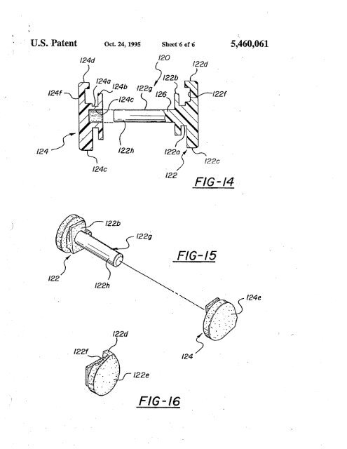
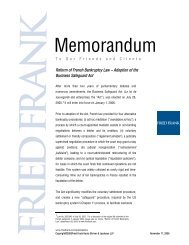
"U .8. ,Patent ,Oct. 24; 1995 Sheet'6<strong>of</strong>6 5,460,061/24'/24d /20/240 )122b/24b 122g/24c /26/22d/22'/24f/24c/22)/22122cF/G-/4/22bF/G-/5/22h124e,/22d/22'/22eFIG-/6
"/ )1ADJUSTABLE CONTROL PEDALAPPARTUSBACKGROUN OF TH INNTON5,46,061Ths <strong>in</strong>vention ri;lates to control peal apparatues andmore parcularly to adjustment meaJor selectively adjust<strong>in</strong>gthe position <strong>of</strong> one or more <strong>of</strong> the control pes <strong>of</strong> amotor vehicle.In a conventiona automotive vehicle, pe are provided 10<strong>for</strong> controllig brakes and eng<strong>in</strong>e thtte. If the vehicle hasa manual trsIIssion, a clutch peda is also provided. Thesepes arc foot operate by the drver. In order <strong>for</strong> the drverto obta the most advantageous position <strong>for</strong> workig thescontrols, the vehicle front seat is usualy slidably mounted .15on a sea trck with mea <strong>for</strong> secg th seat along thetrck and a plurty <strong>of</strong> adjustment positions.The adjustment provided by movig the seat along theset trck does not accommodate al vehicle opeors due to'difference <strong>in</strong> anatomical dimensions. Fu.!thcr, Ll:iere is grw- 20<strong>in</strong>gconcem th the use <strong>of</strong> seat tracks, and espeally longseat trks, constitutes a safety hazar and th the seat maypullloose from the track durig an accident with result<strong>in</strong>junes to the dr ver and/or passengers. It is :tere<strong>for</strong>edesirble to either elirate the seat trk entieÍy or shortn 25the seat track so that it vnl be strng enough to retan theseat durg an imact Shortnig or elig the seattrck reuires that means be prvide to seletively movethe varous control pes to accommode varous sizedñvers. 30Varous proposals were made over ,a peod <strong>of</strong> may yearsto provide selective adjustment <strong>of</strong> the peal positions toaccommodte varous sized drvers, but none <strong>of</strong> these proposalsmet with any signcant commeral acptace s<strong>in</strong>ce 35the proposed mecharsms were unduly complex aId 'expensiveand/or were extremely dicut to ope and/oraccomplish the requir pe adjustment omy at theexpense <strong>of</strong> alteg other crtica diensiona relationshipsas between the drver and the varous pes. Recently, a 40contrl pe mecharsm has been developed which issimple and <strong>in</strong>expensive, easy to opera, and th accom-, plishes the required peda adjustment without alterig othercrtica diensional relationships as between the dñver andth varouspes. Ths contrlpeda mechanm is dis- 45closed <strong>in</strong> U.S. Pat Nos. 4,875,385,4,989,474, and 5,078,024, all assigned to the asgnee <strong>of</strong> th pIent applicaton.The present <strong>in</strong>vention represents improvements to the basicadjustable contrl peda design diclose <strong>in</strong> these patents.SUMY OF TH INNTONTh <strong>in</strong>vention is diected to the proviion <strong>of</strong> a simple and<strong>in</strong>expenSive contrl peal mecanm <strong>in</strong> which the ¡iposition is readiy adjusted without distu<strong>in</strong>g the essential, 55dimensional relationships <strong>in</strong> the contrl env<strong>in</strong>mentThe <strong>in</strong>vention control peda appars <strong>in</strong>ludes an adjustermember mounte <strong>for</strong> movement relative to the motorvducle strctu, ape ar mounted <strong>for</strong> slidig movementalong the adjuster membe means operative to move 60the pe arslidably along the adjuste member, and mesoperative <strong>in</strong> repOnSe to movement <strong>of</strong> the peal ar alongthe adjuster mèmbe to move the pivot axis <strong>of</strong> the Contrlpeal áppars.,Accdig to an.importt fèat <strong>of</strong> the <strong>in</strong>veni:on, the 65adjuster member and ped ar <strong>in</strong>clude coactg mountigportons which dèf<strong>in</strong>ean <strong>in</strong>econ andtheappiitu2<strong>in</strong>cludes a slack taeup assembly positioned at the <strong>in</strong>tesectionand operative to preclude relatve angular movementbetween the adjuster member and peda ar at the <strong>in</strong>terection.Ths arangement elimnates undesied relatve move-S ment as between the peal ar and the adjuster member,whereby to provide a solid peal feel <strong>for</strong> the dñver andelimiate ratte <strong>in</strong> the contrl peal apparatu, whie not<strong>in</strong>terferg with the smooth slidig movement <strong>of</strong> the pealar along the adjuster member.In one embodient <strong>of</strong> the <strong>in</strong>vention, the slack taeupassembly <strong>in</strong>cludes a bracket sere to the peda arproxite the <strong>in</strong>tersection between the peal am and theadjuster member, a block positioned on thebrcket, 'and apluraty <strong>of</strong> plug members mounted <strong>in</strong> the block and extend<strong>in</strong>gbeyond the block to engagea face <strong>of</strong> the adjustemember.In another embodment <strong>of</strong> the <strong>in</strong>vention, the slack taeupassembly <strong>in</strong>cludes a lever member pivotaly mounted on thepeda an proximate the <strong>in</strong>tersecon an adjuster meanopertive to move a toe porton <strong>of</strong> the lever memberupwardly <strong>in</strong>to contat with a fac <strong>of</strong> the adjuster member totae up slack between the members.Accord<strong>in</strong>g to a fuer feate <strong>of</strong> the <strong>in</strong>vention, the mean<strong>for</strong> movig the pivot axs <strong>of</strong> the peal assembly Ii respOnseto slidig movement <strong>of</strong> the ped ar on the adjustermember comprises a car member, a pivot axs p<strong>in</strong> mounted'on the ea member and def<strong>in</strong><strong>in</strong>g the pivot axs <strong>of</strong> the peassembly, and a l<strong>in</strong> connected at one end to thepeal arann cagly coactig at its other end with the eamember. Ths argement provides a readyand effcientmean to selectively move the cam member and thereby thepivot axs even <strong>in</strong> :te cramped envIooment which is tYpica<strong>of</strong> the ar beneath the <strong>in</strong>strent panel <strong>of</strong> a motor vehicle.Accord<strong>in</strong>g to a fuer featue <strong>of</strong> the <strong>in</strong>vention, the eamembér is pivotay mounted on th adjuster member, theone end <strong>of</strong> the li is pivotay mounted on the peal ar andthe other end <strong>of</strong> the li is received <strong>in</strong> a slot <strong>in</strong> the eamembér, and the pivot axs p<strong>in</strong> is received <strong>in</strong> a slot <strong>in</strong> theadjuster member. Ths specic argement provides preciseand positive movement <strong>of</strong> th pivot axs <strong>of</strong> the peassembly <strong>in</strong> response to adjustig movement <strong>of</strong> the pear on the adjuster 'memb.Accrdig to a fuer featu <strong>of</strong> the <strong>in</strong>vention, the means<strong>for</strong> mov<strong>in</strong>g the pivot axs <strong>of</strong> the pè assembly <strong>in</strong> réponsto adjustig movemet <strong>of</strong> the peda ar along theadjustermember <strong>in</strong>clude ll eam membe pivote on the adjustermembe and ÍIcludig a slot and a pivot axs p<strong>in</strong> defig thepivot axs <strong>of</strong> the pedal aSsembly, and a cam p<strong>in</strong> recived <strong>in</strong>50 :te slot and operve <strong>in</strong> response to slidig movement <strong>of</strong> the'pedal appartus on the adjuster member to pivotthe canI'member on the adjuster member and adjust the position <strong>of</strong>the pivot axs p<strong>in</strong> and threby <strong>of</strong> the pivot ax <strong>of</strong> the pedassembly. <strong>in</strong> one embodent <strong>of</strong> th <strong>in</strong>vention, the ea p<strong>in</strong>is mountèd on the pe ar and, <strong>in</strong> another embodiment <strong>of</strong>the <strong>in</strong>vention, the appartu fuer mc1udes a l<strong>in</strong> pivotaymounted at one end on the peal arand theca pi ismounte on the other end <strong>of</strong> the liAccrdng to a fuher feature <strong>of</strong> th <strong>in</strong>vention, th pedaassembly <strong>in</strong>clude first and second contl peda asemblieseah <strong>in</strong>cludig a screw member and a ped ar mounte <strong>for</strong>adjustig movement <strong>in</strong> response to rotation <strong>of</strong> the scrwmember to adjust the position <strong>of</strong> the ped an relative to the'vehicle stict, and the, appar <strong>in</strong>cludes a moto positionedon the motor veIùc1e stctue betwecn the first andsecond pe assemblies an<strong>in</strong>udig a motor dive shaffirst and seCo'èables se to the opposite ends <strong>of</strong> the
- Page 3 and 4: TABLE OF AUTHORITIESPaee(s)Altoona
- Page 5 and 6: United Carbon Co. v. Binney & Smith
- Page 7 and 8: invalidity under 35 U.S.C: § 103 (
- Page 10 and 11: -- In an Offce Action dated Novembe
- Page 12 and 13: just in case there could be an argu
- Page 14 and 15: -- Conventional, off-the-shelf peda
- Page 16 and 17: Here there is no dispute as to any
- Page 18 and 19: n. "OBVIOUSNESS" MUST BE DETERMIND
- Page 20 and 21: Teleflex's argument is erroneous at
- Page 22 and 23: Exs. 8-10; KSR Main Br. at 23-27).
- Page 24 and 25: elements with no change in their re
- Page 26 and 27: mx::0';:¡:-i
- Page 28: ,e ePlaintiffTeleflex Incorporated
- Page 31 and 32: .. ,). ../ IN THE UNTED STATES PATE
- Page 33 and 34: REMAClais 20-23 remai in ths applic
- Page 35 and 36: Offce Action Summaryo Responsive to
- Page 37 and 38: Serial Number: 09/643,422Page 3Ar.U
- Page 39 and 40: mx:J0-;: .t
- Page 41 and 42: 'u.s. Patent . Oct. 24, 1995 Sheet
- Page 43 and 44: u.s. Patent Oct. 24, 1995 Sheet 3 o
- Page 45: , ,U .8. Patent Oct. 24, 1995 Sheet
- Page 49 and 50: 5adjuster member utizig the guide b
- Page 51 and 52: 5,460,0619porton inboard of the slo
- Page 53 and 54: PATENT NO. :DATEDJNVENTOA(S) : ,UNI
- Page 55 and 56: United States Patent (19)Smith et a
- Page 57 and 58: . u.s. Patent Nov. 12, 1991 Sheet 2
- Page 59 and 60: , u.s. Patent Nov. 12, 1991 Sheet 4
- Page 61 and 62: 1ACCELERATOR PEDAL ASSEMBLYTECHNICA
- Page 63 and 64: 565,063,811FIG. 1 to the wide-open-
- Page 65 and 66: 5,063,811910'above, the uppermeans-
- Page 67 and 68: "..._.. .~ --"N~Applicant:EngelgauS
- Page 69 and 70: , .Applicant: EngelgauSN: 09/643,42
- Page 71 and 72: -,.J.."(". ,to . ) , PTO/SS/26 (10-
- Page 73 and 74: 5The subject inventionADJUSTABLE PE
- Page 75 and 76: S 3 'as set fort in clai l wherein
- Page 77 and 78: mx::0';:Q)
- Page 79 and 80: --,.ApplicationOfficë Action Summa
- Page 81 and 82: Serial Number: 09/236,975Page 3Ar U
- Page 83 and 84: mx::0-;:co
- Page 85 and 86: ",U.S.S.N 09/236,975 2..,. .~-,!.,0
- Page 87 and 88: US.S.N 09/236,975 4aft directions t
- Page 89 and 90: mx::0';:-io
- Page 91 and 92: Form PTO-1449 U.S. DEPARTMENT OF AT
- Page 93 and 94: L-Sheet -i of -i ==.5FORM l'O.1449
- Page 95 and 96: Sheet -- of -l.. b ~~ C'~ §g.' l:
- Page 97:
DECLARATION OF JAMES w: DABNEY and