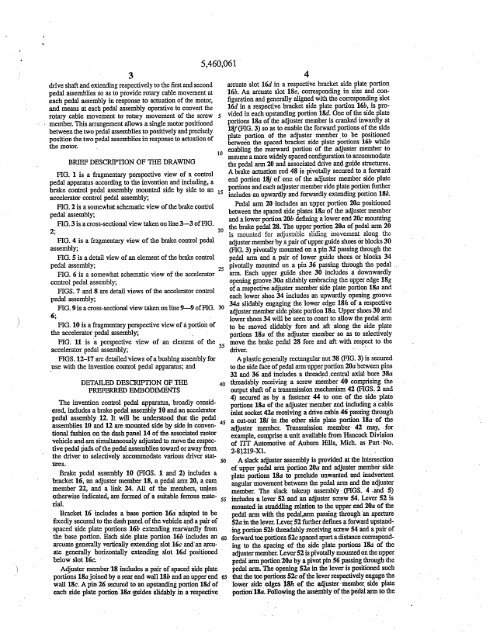
3drve shaf and extendig respectively to the fist and secondped assemblies so as to provide rota cable movement ateach peda assembly <strong>in</strong> response to acation <strong>of</strong> the motor,and mea at each pedal assembly operative to convert therota cable movement to rota movement <strong>of</strong> the screwmember. Ths argement allows a s<strong>in</strong>gle motor positionedbetween the two pedal assemblies to positively and preselyposition the two pedal assemblies <strong>in</strong> responsè to actation <strong>of</strong>the motor.BRIF DESCRON OF TI DRAWIGFIG. 1 is a frgmenta perspeve view <strong>of</strong> a controlpedal appars accord<strong>in</strong>g to the <strong>in</strong>vention and <strong>in</strong>clud<strong>in</strong>g, abrae control ped assembly mounte side by side to an 15acclerar control peal assembly;FIG. 2 is a somewhat sèhemac view <strong>of</strong> the brake controlpedal assembly;FIG. 3 is a cross-sectiona view ta on l<strong>in</strong>e 3-3 <strong>of</strong> FIG.2;FIG. 4 is a fragmenta view <strong>of</strong> the brae, control pedassembly;FIG. 5 is a deta view <strong>of</strong> an element <strong>of</strong> the brae controlpedal assembly;FIG. 6 is a somewhat schematic view <strong>of</strong> the acceleratorcontrol pedal assembly;FIGS. 7 and 8 are detal views <strong>of</strong> the aclerator controlpedal assembly;FIG. 9 is a cross-sectiona view taen on l<strong>in</strong>e 9-9 <strong>of</strong> FIG. 306;FIG. 10 is a fragmenta perspective view <strong>of</strong> å por:on <strong>of</strong>the aceleraor ped assembly;FIG. 11 is 'a perspectve view <strong>of</strong> an element <strong>of</strong> the 35accelera ped assembly;FIGS.12-17 are detaled views <strong>of</strong> a bush<strong>in</strong>g assembly <strong>for</strong>.use with the <strong>in</strong>vention control pedal appars; andDETAIED DESCRON OF ~PREFED EMODIMSThe <strong>in</strong>vention contrl peal appartu, broady considered<strong>in</strong>cludes a bra peda assembly 10 an an ~elettorpedal assembly 12. It wi be understood fuat the peassemblies 10 and U ar mounte side by side <strong>in</strong> conven- 45tiona fahion on the dah panel 14 <strong>of</strong> th associ motorvehicleurs.and ar simultaeously adjuste to movesothe repetivepedal pads <strong>of</strong> the pedal assemblies towa or away fromthe drver to selectively acommodate vanous drver sta-ri.Brae pedal assembly,1n (FGS. 1 an 2) <strong>in</strong>cludes abrket 16, an adjuster member 18, a pedal an 20, a cammember 22, and a l<strong>in</strong> 24. Al <strong>of</strong> the 'members, unlessotherwise<strong>in</strong>dicàted, ar <strong>for</strong>md <strong>of</strong> a suitale ferrus ma- 55Bracket 16 <strong>in</strong>cludes a bas porton 16a' adted to befiedly secured to the dash panel <strong>of</strong> the vehicle and a pai <strong>of</strong>spaced side plate portonS 16b extend<strong>in</strong>g rearardlyfrmthe base porton. Eah side plate porton ,16b <strong>in</strong>cludes an 60arcuat generaly vertcayexrend<strong>in</strong>g slot 16e andan arcuategeneíay horizontay extendg slot 16d positionedbelow slot 16e. 'Adjuster member 18 <strong>in</strong>cludes a pai <strong>of</strong> spaced5,460,-061'side plate, portons 18a jo<strong>in</strong>ed by a rea end wall18b and an upper end 6Swall 18e. A p<strong>in</strong> 26 seCl,ed,to an upstadig poron 18d <strong>of</strong>each side plate porton'l8aogdes slidaly<strong>in</strong> a repective4arcuate slot 16d <strong>in</strong> a respective bracket side plat porton16b. An arcuate slot 18e, correspondig <strong>in</strong> si:ze and i:onfigurationand generaly algned with the corrpondig slot16d <strong>in</strong> a respective bracket side plate porton 16b, is pro-S vided <strong>in</strong> each upstad<strong>in</strong>g porton lSd. One <strong>of</strong> the side plateportons 1Sa <strong>of</strong> the adjuster member is cr <strong>in</strong>wardly at18f (FG. 3) so as to enable the <strong>for</strong>ward portons <strong>of</strong> the sideplate poron <strong>of</strong> the adjuster member, to be positionedbetween the spac bracket side plate portons 16b whieenabl<strong>in</strong>g the reaar porton <strong>of</strong> the adjuste member to10 assume a more widely spaced confgution to acmmodatethe ped ar 20 and assòciated drve and guide strctues.A brake acnition rod 48 is pivotaly secured to a <strong>for</strong>wardend portion 18j <strong>of</strong> one <strong>of</strong> theadjuste memb~r side plateportons and eah adjuster member side plate portion fuer<strong>in</strong>ludes an upwary and <strong>for</strong>wardly extendig porton 18k.Pedal an 20 <strong>in</strong>cIudes an upper poon 20a positionedbetween the spac side plat 18a <strong>of</strong> the adjuster memberand a lower porton 20b defig a lower end 20e mountig20 the brake peda 28. The upper porton 20a <strong>of</strong> pedal an 20is mounted <strong>for</strong> adjustable slidig movement along theadjuster member by apai <strong>of</strong> upper gude shoes Or blocks 30(FG. 3) pivotay mounte on a p<strong>in</strong> 3t pass<strong>in</strong>g though thepeda ar and a pai <strong>of</strong> lower guide shoès ot blocks 3425 pivotay mounte on a p<strong>in</strong> 36 pass<strong>in</strong>g though ,the pedar Each upper guide shoe 30 <strong>in</strong>clude a downwardlyopenig groove 30a slidably embra<strong>in</strong>g the upper edge 18g<strong>of</strong>arespectiveadjuste member side plat porton 1Sa imdeach lower shoe 34 <strong>in</strong>cludes an upwardly openg groove34a slidably engag<strong>in</strong>g the lower edge 18h <strong>of</strong> a respectiveadjuster membe side plate porton 1Sa. Upper shoes 30 andlower shoes 34 wi be sen to coact to alow the pedal arto be moved slidably <strong>for</strong>e and ,af along the side pl¡iteportons 18a <strong>of</strong> the adjuste memj)er so as to selectivelymove the brake pedal 28 <strong>for</strong>e and af with respect to thedrver. .A plastic generaly rectagular nut 38 (FG. 3) is securedto the side face <strong>of</strong> ped ar upper porton 20a beteen p<strong>in</strong>s32 and 36 and <strong>in</strong>cludes a theaded.centt axal bore 38a40 tldably reiv<strong>in</strong>g a screw mèmber 40 compr<strong>in</strong>g theoutput sha <strong>of</strong> a trmission mechasm 42 (FGS. 2and4) sec as by a fastener 44 to one <strong>of</strong> the side platcableportons 1Sa <strong>of</strong> the adjuster member and <strong>in</strong>clud<strong>in</strong>g awet socke 42a receiv<strong>in</strong>g a drve cable 46 pass<strong>in</strong>g thougha cut-out 18i <strong>in</strong> .te other side plate porton 18a <strong>of</strong> theadjuster member. Trsmission member' 42 may, ,<strong>for</strong>example, comprise a unt avaiable from Hancok Diviion<strong>of</strong> m Antomotive <strong>of</strong> Aubur His, Mich. as Par' No.2.8l219-Xl.A slac adjuster assembly is prvide<strong>of</strong> upperped ar :Prton 20a andplate portons 18a to prelude unwante andat the <strong>in</strong>terseconadjuster membeè side<strong>in</strong>dverntanguar movement between the pe an andthe adjustemember. The slac taup assely (FGS. 4 -and 5)<strong>in</strong>cludes a lever 52 and an adjuste screw 54. Lever 52 ismounted <strong>in</strong> strdlg relaton to the upper end lOa <strong>of</strong> thear with the pe,a pass<strong>in</strong>g tlughan apertepedaS2a <strong>in</strong> the lever. Lever '52 fuer defies a <strong>for</strong>ward upstaiid<strong>in</strong>gporton 52b tlly receivig scrw 54 and a pai <strong>of</strong><strong>for</strong>ward toe portons 52c spac apar a distice corrpond-,<strong>in</strong>g to th spac<strong>in</strong>g <strong>of</strong> the side plate portons 1Sa <strong>of</strong> theadjuster member. Lever 52 is pivotaly mounte on theuppepeda ai poron20a by a pivot pi S6 pass<strong>in</strong>g thoughthepeda ar The openig 52a <strong>in</strong> the lever is positioned suchthat the to portons 52c <strong>of</strong> the lever resptively engage thelower side. edges iSh <strong>of</strong> the ,adjuste'rimher_ side platporton'lii. Follow<strong>in</strong>g the'assembly<strong>of</strong> the pe,~ to the
5adjuster member utizig the guide blocks 30 and 34,adjuster scrw 54 is selectaly adjuste to br<strong>in</strong>g toe portons52b <strong>in</strong>to engagement with the lower edges 18h <strong>of</strong> the sideplate portons 18a <strong>of</strong> the adjuster member so as to tae upany slack <strong>in</strong> the slid<strong>in</strong>g assembly <strong>of</strong> the peda an on theadjuster member and preclude relative anguar movement <strong>of</strong>the ped ar relative to the adjuster member, therebyelimitig any anoyig wobble <strong>of</strong> the peal ar relativeto the adjuster membe and any resultat rattg noises.ea member 22 (FGS. 2 and 4) <strong>in</strong>clude an upwardlyextendig <strong>for</strong>ward porton 22 pOsitioned between adjustermember porons 18k and pivotaly mouited on a p<strong>in</strong> 50extendig between the upper ends <strong>of</strong> adjuster member sideplat portons 18k; a lower ar slot 22b; and an upwardlyextend<strong>in</strong>g reard porton 22c mountig a pivot axs p<strong>in</strong> 60(FG. 3) <strong>in</strong>cludig portons 60 extndig lateray fromeach side face <strong>of</strong> the cam membe. Each p<strong>in</strong> porton 60a ispositioned <strong>in</strong> arcuate slots 18e and 16c <strong>of</strong> a respetiveadjuste member porton 1M and bracket poon 16b.L<strong>in</strong>k 24 is pivotaly mounted at its rearard end 24 to theuppe porton 2òa <strong>of</strong> the pedar above nut 38 as, <strong>for</strong>example, by a pi 62 and <strong>in</strong>cludes a cam p<strong>in</strong> 64 mounted onits <strong>for</strong>ward end 24band camgly and slidaly received <strong>in</strong>cam member slot 22b. L<strong>in</strong> 24 <strong>in</strong>cludes a cr porton 24cto accomiodte the latera displacement <strong>of</strong> the cam platerelative to the peal ar.Cable 46 is drvigly secured to one end <strong>of</strong> the outputshaf 66a <strong>of</strong> a small elecc motor 66 (FG; 3) seured to thedash panel 14 <strong>of</strong> the vehicle between bre peal assembly10 and accelertor pedàl assembly 12.It wil be seen th eIiergation <strong>of</strong> motor ,66 results <strong>in</strong>rotation <strong>of</strong> cable 46. The rotaon <strong>of</strong> cable 46 is conver bytrmission device 42 <strong>in</strong>to rota movànent <strong>of</strong> screw 40wmch <strong>in</strong> tu coacts wtti nut 38 to produce liea or slidigmovement <strong>of</strong> pedal ar,' 20 along adjuster member 18 toselectively adjust the position <strong>of</strong> pe pad 28 relative to thedrver. As the pe ai moves <strong>for</strong>e and af reiatveto theadjuster member18, th li 24 is moved <strong>for</strong>e and af tomove cam p<strong>in</strong> 64 <strong>in</strong> ea plate slot 22 so as to selectivelypivot the ea plate abut th axs <strong>of</strong> p<strong>in</strong> 50 and selectivelymove pivot axs p<strong>in</strong> 60 upwardly and downwary <strong>in</strong> algnedarcuat slots 18e, 16c so as to selectively adjust the pivotaxs <strong>of</strong> the pe ar and the adjute member as the position<strong>of</strong> the ped ar is adjusted relatve to the adjuster member.The viuous pareters <strong>of</strong> the apparat ar pieferly 45chosen such that the movement <strong>of</strong> the pivot ax,<strong>in</strong> responseto adjustig movement <strong>of</strong> the peal ar on, the adjustemember ha the effect <strong>of</strong> maig a substatialy constatratio between the distace from th pivot axs to thepeal pad and the distace frm the pivot, axs to the 50atthment po<strong>in</strong>t <strong>of</strong> the braeactuon ro 48 so as tomata a substatialy unor mecJical advatage andrelÙtat feel <strong>for</strong> th bre ped assembly iiespetive <strong>of</strong> thememb,er S5adjusted position <strong>of</strong> the pe ar relative to the adjusteAcce1eor pe assembly 12 (FG.1) <strong>in</strong>cludes a braket70, an adjuster member 72, a pedal ar 74, and' a eamember 76. Al <strong>of</strong> the members, uness otherwise <strong>in</strong>dicatedar <strong>for</strong>med <strong>of</strong> a suitale ferous maal.Brackt 70 <strong>in</strong>cludes a base porton 70a secued to the dahpaneltion.14 <strong>in</strong> latery space relation to the65brae peæsembly and a pai <strong>of</strong> side plate poons 70b extendigrearardly from base porton 70a <strong>in</strong> lateraly 'spac rela-Adjuste membe 72 (FG. 6) <strong>in</strong>cludes spaced side plateportons 72a jo~ at a reard end wal 72b. One <strong>of</strong> the5,460,0616side plate portons tla <strong>in</strong>cludes a <strong>for</strong>ward upwardly extend<strong>in</strong>gporton 72c def<strong>in</strong>ig an atthment flange porton 72d atits upper end <strong>for</strong> atthment <strong>of</strong> the accelerator contrl cale78. A guide p<strong>in</strong> 80 proximate the base <strong>of</strong> upstadig porton5 72c guides <strong>in</strong> an arcuate guide groove 70c <strong>in</strong> one <strong>of</strong> the baseside plate portions 70b. Each <strong>of</strong> the side plate poons 7ladefies an aruate ,generally vertcaly extndig groove 72eproxite its <strong>for</strong>ward end which is vercally aligned with,and correspondig <strong>in</strong> configution to, an arcuae groove10 70d <strong>in</strong> the assocate bracket side plate porton 70b.'Peda ar 74 (FG. 10) has a hollow reaardlyopenigU-shape èonfgurtion <strong>in</strong> cross section and <strong>in</strong>cludes anupper porton 74a positioned between adjuster member sideplate portons tla and a lower porton 74b def<strong>in</strong>ig a loweris end 74c (FG. 6) <strong>for</strong> pivota or fixe athment <strong>of</strong> anaclerator peda 82. A pai <strong>of</strong> upper guide blocks84 arpivotay positioned on opposite sides <strong>of</strong> the upper porton74a <strong>of</strong> the pe ar by a p<strong>in</strong> 86 pass<strong>in</strong>g though the pear and a pai <strong>of</strong> lower guide blocks 88 ar pivotay20 positioned on opposite sides <strong>of</strong> the upper porton 74a <strong>of</strong> tbepeda ar by a p<strong>in</strong> 90 pass<strong>in</strong>g though t,e peda block. Eachupper guide block 84 defies a downwary openigU-shaped grove 84 slidably engagig th upper edge 72/(FIG. 6) <strong>of</strong> a respective adjuster membe side plate porton25 tla and each lower block 88 defies ai upwardly open<strong>in</strong>gU-shaped groove 88a slidably engagig the lower edge 72g(FG. 6) <strong>of</strong> a respective adjuster member side plate porton72a. Upper and lower gude blocks 84 and RS wil be seento mount the peal an <strong>for</strong> selectve slid<strong>in</strong>g <strong>for</strong>e and af30 movement along the adjuster membr, 72 to adjust theposition <strong>of</strong> the aceleraor pedal 82 relative to the drver.A plastic nut 92 (FGS. 9 and II)) is fixedly positionedbetween the space side wals 74d<strong>of</strong> the upper end <strong>of</strong> thepe ar and <strong>in</strong>cludes a thded b()Ie 92a theadably35 reciv<strong>in</strong>g a screw member 94 secured to the output shaf <strong>of</strong>a tranmission device 96 (FG. 6) suitaly secured to one <strong>of</strong>the side plate portons 72a <strong>of</strong> the adjuster member and<strong>in</strong>clud<strong>in</strong>g a cable iIput fittg 96, Jecivig, a cable 98connecte to the other end <strong>of</strong> the output sha 66 <strong>of</strong> electrc40 motor 66 (FG. 3). Tranmission device 96 may be identica. to the trsmission device 42 <strong>of</strong> the brae pe assembly.It wil be seen tht energiaton <strong>of</strong> motor 66 provides rotacable movement to the aclertor assembly 12 which isconverd to rotar movement <strong>of</strong> screw niember 94 bytrsmission device 96 so as to move the pe an <strong>for</strong>e andaf slidably along the adjuster member to Selectively adjustthe position <strong>of</strong> accelerator peal 82 relatve to the drver.A slack taeup device 100 (FGS. 6, 7, Sand 18) ispositioned at the <strong>in</strong>tersecon <strong>of</strong> the upper en 74a <strong>of</strong> thepear and the adjuster meiber. Slack taup deVice 100<strong>in</strong>èlude a braket 102 secured as by weldig to the re face74e <strong>of</strong> the ped ar immedately below the <strong>in</strong>rsection <strong>of</strong>the ped ar and the adjuster member, and a plastic block104 <strong>in</strong>clud<strong>in</strong>g a groove l04a receivig the ~ard end,porton 10la <strong>of</strong> brket 102 so as to position the blocl 104<strong>in</strong> underly<strong>in</strong>g relation to the adjacnt porton <strong>of</strong> the adjustemember. Takeup assembly 100 fur <strong>in</strong>cludes a pai <strong>of</strong>plugs 106 reeived <strong>in</strong> a pai <strong>of</strong>vercal bore 104b <strong>in</strong> block104 and <strong>in</strong>cludig ratchet teeth 106a. Plugs 106 may, <strong>for</strong>60 example, be <strong>of</strong> the type avaiable frm Pen Engieenngand Manufuctg Company <strong>of</strong> Danbcro, Pa as Par No.NPPA~M5. Followig the a&Stmbly <strong>of</strong> the pe ar to theadjuste member to mount the pedi ar slidably on theadjuster membr, plugs 106 are <strong>in</strong>ert upwary though, bores 1,06a until the upper ends 106b <strong>of</strong> the pl\lgs engage thelower edges 72g <strong>of</strong> the sidear portnns tla <strong>of</strong> the adjustrmembe so as to tae up slack <strong>in</strong> the pe an,and adjuste
- Page 3 and 4: TABLE OF AUTHORITIESPaee(s)Altoona
- Page 5 and 6: United Carbon Co. v. Binney & Smith
- Page 7 and 8: invalidity under 35 U.S.C: § 103 (
- Page 10 and 11: -- In an Offce Action dated Novembe
- Page 12 and 13: just in case there could be an argu
- Page 14 and 15: -- Conventional, off-the-shelf peda
- Page 16 and 17: Here there is no dispute as to any
- Page 18 and 19: n. "OBVIOUSNESS" MUST BE DETERMIND
- Page 20 and 21: Teleflex's argument is erroneous at
- Page 22 and 23: Exs. 8-10; KSR Main Br. at 23-27).
- Page 24 and 25: elements with no change in their re
- Page 26 and 27: mx::0';:¡:-i
- Page 28: ,e ePlaintiffTeleflex Incorporated
- Page 31 and 32: .. ,). ../ IN THE UNTED STATES PATE
- Page 33 and 34: REMAClais 20-23 remai in ths applic
- Page 35 and 36: Offce Action Summaryo Responsive to
- Page 37 and 38: Serial Number: 09/643,422Page 3Ar.U
- Page 39 and 40: mx:J0-;: .t
- Page 41 and 42: 'u.s. Patent . Oct. 24, 1995 Sheet
- Page 43 and 44: u.s. Patent Oct. 24, 1995 Sheet 3 o
- Page 45 and 46: , ,U .8. Patent Oct. 24, 1995 Sheet
- Page 47: "/ )1ADJUSTABLE CONTROL PEDALAPPART
- Page 51 and 52: 5,460,0619porton inboard of the slo
- Page 53 and 54: PATENT NO. :DATEDJNVENTOA(S) : ,UNI
- Page 55 and 56: United States Patent (19)Smith et a
- Page 57 and 58: . u.s. Patent Nov. 12, 1991 Sheet 2
- Page 59 and 60: , u.s. Patent Nov. 12, 1991 Sheet 4
- Page 61 and 62: 1ACCELERATOR PEDAL ASSEMBLYTECHNICA
- Page 63 and 64: 565,063,811FIG. 1 to the wide-open-
- Page 65 and 66: 5,063,811910'above, the uppermeans-
- Page 67 and 68: "..._.. .~ --"N~Applicant:EngelgauS
- Page 69 and 70: , .Applicant: EngelgauSN: 09/643,42
- Page 71 and 72: -,.J.."(". ,to . ) , PTO/SS/26 (10-
- Page 73 and 74: 5The subject inventionADJUSTABLE PE
- Page 75 and 76: S 3 'as set fort in clai l wherein
- Page 77 and 78: mx::0';:Q)
- Page 79 and 80: --,.ApplicationOfficë Action Summa
- Page 81 and 82: Serial Number: 09/236,975Page 3Ar U
- Page 83 and 84: mx::0-;:co
- Page 85 and 86: ",U.S.S.N 09/236,975 2..,. .~-,!.,0
- Page 87 and 88: US.S.N 09/236,975 4aft directions t
- Page 89 and 90: mx::0';:-io
- Page 91 and 92: Form PTO-1449 U.S. DEPARTMENT OF AT
- Page 93 and 94: L-Sheet -i of -i ==.5FORM l'O.1449
- Page 95 and 96: Sheet -- of -l.. b ~~ C'~ §g.' l:
- Page 97: DECLARATION OF JAMES w: DABNEY and