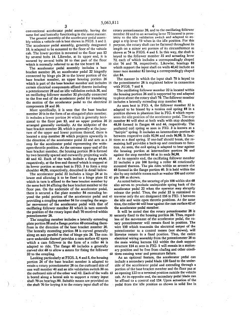
5,063,8113-cønventional accele,rat~r peal assembly, hav<strong>in</strong>g ,thesame feel and basically function<strong>in</strong>g <strong>in</strong> the same ,manner,The general assembly <strong>of</strong> the accelerator pedal assemblywith<strong>in</strong> a vehicle cab is best shown <strong>in</strong> FIGS. 1 and 2.The accelerator pedal assembly, generally designated 510, is adapted to be mounted to the floor <strong>of</strong> the vehiclecab. The lower portion is mounted to the floor pan .1by several bolts 14. Likewise, at its upper end, it issecured by 'several bolts 16 to that part <strong>of</strong> the floorwhich is normally referred to as the toe board 18.The accelerator pedal assembly <strong>in</strong>cludes a base,bracket member 20, an accelerator pedal 22 h<strong>in</strong>gedlyconnected by h<strong>in</strong>ge p<strong>in</strong> 24 to the lower portion <strong>of</strong> thebase bracket member, an upper hous<strong>in</strong>g portion 26which is part <strong>of</strong> the base bracket member and <strong>in</strong>cludes IScertan electrical components affxed thereto <strong>in</strong>clud<strong>in</strong>ga potentiometer 28 and an idle validation switch 30, andan oscilat<strong>in</strong>g follower member 32 pivotally connected'to the free end <strong>of</strong> the accelerator pedal <strong>for</strong> translat<strong>in</strong>gthe motion <strong>of</strong> the accelerator pedal to the electrical 20components 28 and 30.More specificaly, it is seen that the base bracketmember 20 is <strong>in</strong> the <strong>for</strong>m <strong>of</strong> an elongated plate member.-It <strong>in</strong>cludes a lower portion 34 which is generally horizontalto the floor pan 12, and an upper porton 36 25arranged generally vertically. At the midpo<strong>in</strong>t <strong>of</strong> thebase bracket member 20, which is generally at thejuncture<strong>of</strong> the upper and lower portions there<strong>of</strong>, there islocated a stop member 38 which projects upwardly <strong>in</strong>the direction <strong>of</strong> the accelerator pedal 22 and acts as a 30stop <strong>for</strong> the accelerator pedal represent<strong>in</strong>g the wideopen-throttleposition. At the extreme upper end <strong>of</strong> the "base bracket membe, the hous<strong>in</strong>g portion 26 is <strong>for</strong>medby two laterally spaced and outwardly project<strong>in</strong>g walls40 and 42. Each <strong>of</strong> the Walls <strong>in</strong>clude a flange 44,46, 35respectively, at the free end there<strong>of</strong> which is stepped at,its lower portion as seen best <strong>in</strong> FIG. 3 to <strong>for</strong>m a stopshoulder 48,50, respectively, described <strong>in</strong> detail below.The accelerator peal 22 <strong>in</strong>cludes a h<strong>in</strong>ge 24 at itslower end, allow<strong>in</strong>g it to be fixed toa h<strong>in</strong>ge plate 52 40'which <strong>in</strong> turn is affxed to the bas bracket member bythe sae bolt 14 affx<strong>in</strong>g the bas bracket member tò thefloor pan. Oii the undersde <strong>of</strong> the accelerator pedal,there is secured a flat plate, member 54 extend<strong>in</strong>g be, yond the pedal portion <strong>of</strong> the accelerator pedal and 45provid<strong>in</strong>g a coupl<strong>in</strong>g member 56 <strong>for</strong> coupl<strong>in</strong>g the angularmovement <strong>of</strong> the acclerator pedal with that <strong>of</strong>oscilat<strong>in</strong>g follower membe 32 which <strong>in</strong> turn controlsthe position <strong>of</strong>the rotar <strong>in</strong>put shaft 70 received withpotentiometer 28. " 50The' coupl<strong>in</strong>gmember <strong>in</strong>cludes a laterally extend<strong>in</strong>gplate portiori 58 and a flange portion 60 extend<strong>in</strong>g therefrom<strong>in</strong> thé direction <strong>of</strong> the nasebracket member 20.The laterally éxtendÌiig porton 58 is curved generallyalong an axs parallel to tht <strong>of</strong> h<strong>in</strong>ge p<strong>in</strong> 24. The con- '55cave underside there<strong>of</strong> provides a carsurface Iii upon'which a ear follower <strong>in</strong> the, <strong>for</strong>m <strong>of</strong> a roller 66 isadapted to ride. The flange 60 .<strong>in</strong>cludes a generallycurved slot 68 to allow a means <strong>for</strong> fix<strong>in</strong>g the follower32 tothe coupl<strong>in</strong>g. tíLok<strong>in</strong>g parcularly at FIGS. 3, 4 and 5, the hous<strong>in</strong>g'portion 26 <strong>of</strong> the base bracket member is adapted toretan a rot3. potentiometer 28 ön the outboard side <strong>of</strong>one wall member 40 and an idle validation switch 30 onthe outboard side <strong>of</strong> the other wall 42. Each <strong>of</strong> the walls 65is bored alòng a, lateral axis to support arotary <strong>in</strong>putmeans are provided onshaft 70 on. bear<strong>in</strong>gs'SO. Suitablethe shaft 7¡Hor key<strong>in</strong>g it,to the rotary <strong>in</strong>put shaft <strong>of</strong> the4r.otary potentiometer 28; and to the oscillat<strong>in</strong>g followermember 32 and to an actuat<strong>in</strong>g lever 72 located <strong>in</strong> prox<strong>in</strong>lityto the idle validation switch and adapted to engagea trip lever 73 when <strong>in</strong> the idle position. For thispurpose, the rotary shaft can be flattened throughout itslength on a m<strong>in</strong>or arc portion <strong>of</strong> its circumference asshown at 74 <strong>in</strong> FIGS. 4 and 5. In this way, the shaft iskeyed to the follower member 32 and actuat<strong>in</strong>g lever72, each <strong>of</strong> which <strong>in</strong>cludes a correspond<strong>in</strong>gly shaped10 slot 76 and 78, respectively. Likewise, bear<strong>in</strong>gs 80which support the <strong>in</strong>put shaft on walls 40,42 <strong>in</strong>clude an<strong>in</strong>ner race member 82 hav<strong>in</strong>g a correspond<strong>in</strong>gly shapedslot 84.The manner <strong>in</strong> which the <strong>in</strong>put shaft 70 is keyed tothe potentiometer 28 is expla<strong>in</strong>ed below <strong>in</strong> connectionwith FIGS. 7 and 8.The oscilat<strong>in</strong>g follower member 32 is located with<strong>in</strong>the hous<strong>in</strong>g portion 26 and is supported by and adaptedto pivot about the rotary shaft 70. The follower member<strong>in</strong>cludes a laterally extend<strong>in</strong>g stop member 86.As seen- best <strong>in</strong> FIG. 4, the follower member 32 is, adapted' to be biased by a torsion coil spr<strong>in</strong>g 88 <strong>in</strong> aposition shown <strong>in</strong> phantom J<strong>in</strong>e<strong>in</strong> FIG. 4 which representsthe idle ,position <strong>of</strong> the accelerator pedaL. Tne stopmember 86 wil abut at both walls with stop shoulders48,50 <strong>for</strong>med <strong>in</strong> flanges 44 and 46, respectively. Thepreferred coil spr<strong>in</strong>g as seen <strong>in</strong> FIG. 3 is known as a"harp<strong>in</strong>" spr<strong>in</strong>g. It <strong>in</strong>cludes an <strong>in</strong>termediate portion 90between respective coils 92,94 and ends 96,98. It functionsas a dual spr<strong>in</strong>g. If one-half should break, the rema<strong>in</strong><strong>in</strong>ghalf provides a back-up and cont<strong>in</strong>ues to function.As seen, the coil spr<strong>in</strong>g is adapted to bear aga<strong>in</strong>stthe hous<strong>in</strong>g portion at <strong>in</strong>termediate portion 36 andaga<strong>in</strong>st the stop member 86 at its ends 96,98.At its opposite end, the oscilat<strong>in</strong>g follower member32 <strong>in</strong>cludes a p<strong>in</strong> ioo hav<strong>in</strong>g a roller 66 rotationallymounted thereon., The p<strong>in</strong> rides with<strong>in</strong> an arcuate slot68 <strong>for</strong>med <strong>in</strong> the flange portion 60. It is held with<strong>in</strong> theslot by any suitable means such ,as washer 106 and cotterp<strong>in</strong> 108 as shown.As noted below, the secur<strong>in</strong>g <strong>of</strong> p<strong>in</strong> 100 with<strong>in</strong> slot 68also serves to preclude undesirable spr<strong>in</strong>g back <strong>of</strong> theaccelerator pedal 22 when the operator _may abruptlyreleas the pedaL. Thus, the pedal 22 is restra<strong>in</strong>ed totraverse only the arc designated 116 <strong>in</strong> FIG. 1 betweenthe idle and wide open throttle positions. At the sal1etime, the roller 66 wil be aga<strong>in</strong>st the ea surface 62 <strong>of</strong>thè accelerator pedal member.It wil be noted that the rota potentiometer 28 issecurely fixed to the hous<strong>in</strong>g portion 26. Thus, regaidless<strong>of</strong> the movement <strong>of</strong> the accelerator pedal, the rotarypotentiometer will rema<strong>in</strong> fixed <strong>in</strong> position~ Thewire 110 which transmits the electrical output <strong>of</strong> thepotentiometer to alikewise rema<strong>in</strong> <strong>in</strong>' a fixed position. Thus,electrical wir<strong>in</strong>gcontrol means (not shown), wilthe ' entireassembly from the potentiometer 28 tothe ma<strong>in</strong> wig harness 112 with<strong>in</strong> the dash supportstructure 114 as seen <strong>in</strong> FIG. i wil rema<strong>in</strong> <strong>in</strong> a station-, ary position and be free from chafng and other conditionscaus<strong>in</strong>g, wear and premature failure:As an optional feature, the accelerator pedal can<strong>in</strong>clude a secondary pedal blade 120 fixed to the underside<strong>of</strong> the accelerator pedal and extend<strong>in</strong>g through aportion <strong>of</strong> the base bracket member and the floor pan atan open<strong>in</strong>g 122, to a terIn<strong>in</strong>al position outside the vehiclecab. At its opposite end. the secondary peal blade canbe affxed to a control rod 124. Upon actuation <strong>of</strong> thepedal from the 'idle position- as shown <strong>in</strong> solid l<strong>in</strong>e <strong>in</strong>
565,063,811FIG. 1 to the wide-open-throttle position as represented computerized control (not shown) that there is a mal<strong>in</strong>phantom l<strong>in</strong>e <strong>in</strong> FIG. I, the secondary peçlal blade function or a concern to be acted upon.wil translate the control rod 124 over an axial travel . The follower member 220 comprises a pair <strong>of</strong> annspath <strong>in</strong>dicated at 126. The control rod 124 as controlled 266 and 268. Each is connected to the other as a rigidby the secondary pedal blade can either operate or be 5 structure by p<strong>in</strong>s 270. At one end <strong>of</strong> the follower memoperatedby mechanism components outside the vehicle bers, 'there is provided a car follower <strong>in</strong> the fonn <strong>of</strong> acab, e.g., mechanically modulated automatic transmis- roller 272 rotatably mounted on a p<strong>in</strong> 274 which extendssions. though the slot 234 <strong>of</strong> accelerator pedal flange 230.In FIGS. 6-8, there is shown an alternative embodi- The cam follower bers aga<strong>in</strong>st earn surface 232 <strong>in</strong> thement to the accelerator pedal assembly. 10 same manner as described previously <strong>in</strong> connectionThe accelerator pedal assembly 200 <strong>in</strong>cludes with the embodiment shown <strong>in</strong> FIGS. 1-5.sae basiC components, namely, an accelerator pedal The follower member 220 is spr<strong>in</strong>g biased by torsion210, a base bracket member 212 hav<strong>in</strong>g a hous<strong>in</strong>g por- coil spr<strong>in</strong>g 276 <strong>in</strong> the idle position as shown <strong>in</strong> solid l<strong>in</strong>e276 istion 214 with a rotay potentiometer 216 and idle vali~ <strong>in</strong> FIG. 6. For purposes <strong>of</strong> clarty, the spr<strong>in</strong>gdation switch 218 mounted thereon, and a spnng biaed 15 omitted from FIG. 7. A p<strong>in</strong> 278 extends from wall 250follower member 220 rotatably supported on apotenti- to wall 280 <strong>of</strong> the hous<strong>in</strong>g and acts as a stop memberometer <strong>in</strong>put shaft 222 at one end and coupled to the aga<strong>in</strong>st which the top side <strong>of</strong>the anns 266,268 wil bearaccelerator pedal 210 at its other end. as seen <strong>in</strong> FIG. 6. One ann member 266 <strong>in</strong>cludes at itsThe accelerator peda 210 has a s<strong>in</strong>gle rubber covered opposite end an elongated actuat<strong>in</strong>g lever 280 whichplate member 224 hav<strong>in</strong>g a h<strong>in</strong>ge 226 at its lower end 20 engages the idle validation switch <strong>in</strong> the same manner asand a coupl<strong>in</strong>g member 228 at its upper end. Laterally lever 72 <strong>of</strong> the earlier described embodiment.extendif!g' plate portion 230 <strong>in</strong>cludes a earn surface 232 Other than the <strong>for</strong>ego<strong>in</strong>g, the embodiment shown <strong>in</strong>at its underside. However, unlike the embodiInents FIGS. 6-8 is the same as that shown <strong>in</strong> the earlier deshoVv"n<strong>in</strong> FIGS. j-S, the carn surface is flat rather than scribed embodiment and the operation is also the samearcuate, and the slot 234 is l<strong>in</strong>ea rather than arcuate. 25 as that to be described <strong>in</strong> connection with the first em-With the present arrgement, the deviation <strong>in</strong> the rota- bodiment.tion <strong>of</strong> the follower member 220 as a l<strong>in</strong>ear relationship In operation, the driver applies pressure to the pedato the rotation <strong>of</strong> accelerator pedal 210 is electronically 22 and <strong>for</strong>i; it aga<strong>in</strong>st the bias <strong>of</strong> spr<strong>in</strong>g 88 towardsadjusted by a suitable control circuit. wide-open-throttle to accelerate, then releases the pres-The base bracket member 212 comprises a lower 30 sure to allow the pedal to return toward idle, caus<strong>in</strong>gportion 236 <strong>for</strong>med as a stamp<strong>in</strong>g and an upper portion the vehicle to' slow down. As the driver pushes the238 <strong>for</strong>med as a cast<strong>in</strong>g. The two members, may be 'pedal down, the cam surface 62 <strong>for</strong>ces rotation <strong>of</strong> themember 32 to whichsecured to one another by the sae bolt 24 securng cam follower 66 and the followerthe assembly to the toe board. Secured to the lower it is p<strong>in</strong>ned. When the driver removes the pedal presmember236 at the <strong>in</strong>tennediate portion <strong>of</strong> the base 35 sure,. the followermember 32, be<strong>in</strong>g spr<strong>in</strong>g loaded,bracket member is a stop member 242 <strong>in</strong> the fonn <strong>of</strong> a rotates back to the idle position, <strong>for</strong>c<strong>in</strong>g the pedal backthreaded bolt 24 hav<strong>in</strong>g a rubber head 24 andthread- to its idle position. Each oscilation <strong>of</strong> thet'ollower<strong>in</strong>gly recived with<strong>in</strong> nut member 24 which is affxed member causes rotation <strong>of</strong> the potentiometer <strong>in</strong>put shaftto the lower member 236. The height <strong>of</strong> stop member 70 which drves the electricalpedal position <strong>in</strong>dicat<strong>in</strong>g242 may be adjusted by turn<strong>in</strong>g it relative to the nut 24. 40 components 28 and 30 <strong>of</strong> the asembly.Look<strong>in</strong>g at the hous<strong>in</strong>g portion 214, the potentiome- Rotation <strong>of</strong> the <strong>in</strong>put shaft 70 rotates the resistiveter 216 is, secured to the outboard side <strong>of</strong> wall 250 element <strong>of</strong> the potentiometer, varng the output voltthere<strong>of</strong>while the idle validation switch 218 is secured iige leveL. The eomputer then reads the voltage level,on the <strong>in</strong>terior side <strong>of</strong> the same wall 250. compares this with stored <strong>in</strong>fonnation correlat<strong>in</strong>g volt-As shown paricularly <strong>in</strong> FIGS. 7 and 8, the <strong>in</strong>put 4S age level and pedal position, and detenn<strong>in</strong>es the pedalshaft 222 is received with<strong>in</strong> the potentiometer 216 and position.iicludes an elongated, rectangularly cross-sectioned tab <strong>in</strong>e design <strong>of</strong> most s<strong>of</strong>tware logic requires the use <strong>of</strong>252 at its end. The iabis designed to slid<strong>in</strong>gly <strong>in</strong>terft an idle validation switch 30. The switch is' actuated by<strong>in</strong>put shat 70 as the pedalwith<strong>in</strong>a'slot 256 <strong>for</strong>med by appoitely disposed'quad- ,trp lever 73 on the rotat<strong>in</strong>grat sectors 258 on the <strong>in</strong>put member <strong>of</strong> the potentiome- SO leaves or teturn to 'the idle position. The changig stateter. Eåch quadrant sector 258 has a dñv<strong>in</strong>g race 260.' <strong>of</strong> the switch is monitored by the computer, and com-:Between the quadrant sectors is an open quadrat sec- pared'ta the signal from the potentiometer. Th comtion262. In operation, the <strong>in</strong>put member 264 is driven <strong>in</strong> parsen is used as a protective measure aga<strong>in</strong>st potentithediection<strong>of</strong>the arow as the pedal moves from the, ometet <strong>in</strong>alrunètion. ', idle position to the wide open throttle' position. The 55 ' Torsionspñng 88 returns the pedal back to the idledñven <strong>in</strong>put member is sprig biased <strong>in</strong>' a dirècon ' positionand provides resistance to the pressure exertedopposite that <strong>of</strong> the arrow. As ,a saety feature, should by the drver's foot. When the operator reduces thethe <strong>in</strong>put member 264 fail to, return to the idle position, pedal <strong>for</strong>ce, the torque from, the spr<strong>in</strong>g' act<strong>in</strong>g on thebackthe open qiadrantsection 262 wil allow the <strong>in</strong>put sha' 'follower member 32 rotates the follower and pedal222 to rotate 90°; which is suffcient to allow it to'retil 60 to idle. The spr<strong>in</strong>g provides a reSistance to pedal rotatothe idle position, thereby preclud<strong>in</strong>g what might tionby push<strong>in</strong>g the pedal back agaist the driver's foot.otherwise be a possibilty thatthe <strong>in</strong>put shaft and thus Th r~stance <strong>in</strong>creases as the pedal rotateS towardsthe accelerator, pedal asembly, would be held <strong>in</strong> an side open throttle position requir<strong>in</strong>g the driver to applyopen throttle, position; Thus, the accelerator pedal ,as- an <strong>in</strong>creas<strong>in</strong>g amount <strong>of</strong> pedal ef<strong>for</strong>tsembIy rema<strong>in</strong>s operationaL. The idle validation switch 6S The motion <strong>of</strong> the pedal is constra<strong>in</strong>ed at the widewil <strong>in</strong>dicate &hatthè accelerator pedal is iIi the idle open throttle position and the idle position by the baseposition wherea the potentiometer wil ,<strong>in</strong>dicate that it briiçket member 20. When the pedal reaches the wideis <strong>in</strong> an open throttle position, thus <strong>in</strong>dièatlngto the ,open throttle posttion, it' is halted, by the, wide open
- Page 3 and 4:
TABLE OF AUTHORITIESPaee(s)Altoona
- Page 5 and 6:
United Carbon Co. v. Binney & Smith
- Page 7 and 8:
invalidity under 35 U.S.C: § 103 (
- Page 10 and 11:
-- In an Offce Action dated Novembe
- Page 12 and 13: just in case there could be an argu
- Page 14 and 15: -- Conventional, off-the-shelf peda
- Page 16 and 17: Here there is no dispute as to any
- Page 18 and 19: n. "OBVIOUSNESS" MUST BE DETERMIND
- Page 20 and 21: Teleflex's argument is erroneous at
- Page 22 and 23: Exs. 8-10; KSR Main Br. at 23-27).
- Page 24 and 25: elements with no change in their re
- Page 26 and 27: mx::0';:¡:-i
- Page 28: ,e ePlaintiffTeleflex Incorporated
- Page 31 and 32: .. ,). ../ IN THE UNTED STATES PATE
- Page 33 and 34: REMAClais 20-23 remai in ths applic
- Page 35 and 36: Offce Action Summaryo Responsive to
- Page 37 and 38: Serial Number: 09/643,422Page 3Ar.U
- Page 39 and 40: mx:J0-;: .t
- Page 41 and 42: 'u.s. Patent . Oct. 24, 1995 Sheet
- Page 43 and 44: u.s. Patent Oct. 24, 1995 Sheet 3 o
- Page 45 and 46: , ,U .8. Patent Oct. 24, 1995 Sheet
- Page 47 and 48: "/ )1ADJUSTABLE CONTROL PEDALAPPART
- Page 49 and 50: 5adjuster member utizig the guide b
- Page 51 and 52: 5,460,0619porton inboard of the slo
- Page 53 and 54: PATENT NO. :DATEDJNVENTOA(S) : ,UNI
- Page 55 and 56: United States Patent (19)Smith et a
- Page 57 and 58: . u.s. Patent Nov. 12, 1991 Sheet 2
- Page 59 and 60: , u.s. Patent Nov. 12, 1991 Sheet 4
- Page 61: 1ACCELERATOR PEDAL ASSEMBLYTECHNICA
- Page 65 and 66: 5,063,811910'above, the uppermeans-
- Page 67 and 68: "..._.. .~ --"N~Applicant:EngelgauS
- Page 69 and 70: , .Applicant: EngelgauSN: 09/643,42
- Page 71 and 72: -,.J.."(". ,to . ) , PTO/SS/26 (10-
- Page 73 and 74: 5The subject inventionADJUSTABLE PE
- Page 75 and 76: S 3 'as set fort in clai l wherein
- Page 77 and 78: mx::0';:Q)
- Page 79 and 80: --,.ApplicationOfficë Action Summa
- Page 81 and 82: Serial Number: 09/236,975Page 3Ar U
- Page 83 and 84: mx::0-;:co
- Page 85 and 86: ",U.S.S.N 09/236,975 2..,. .~-,!.,0
- Page 87 and 88: US.S.N 09/236,975 4aft directions t
- Page 89 and 90: mx::0';:-io
- Page 91 and 92: Form PTO-1449 U.S. DEPARTMENT OF AT
- Page 93 and 94: L-Sheet -i of -i ==.5FORM l'O.1449
- Page 95 and 96: Sheet -- of -l.. b ~~ C'~ §g.' l:
- Page 97: DECLARATION OF JAMES w: DABNEY and