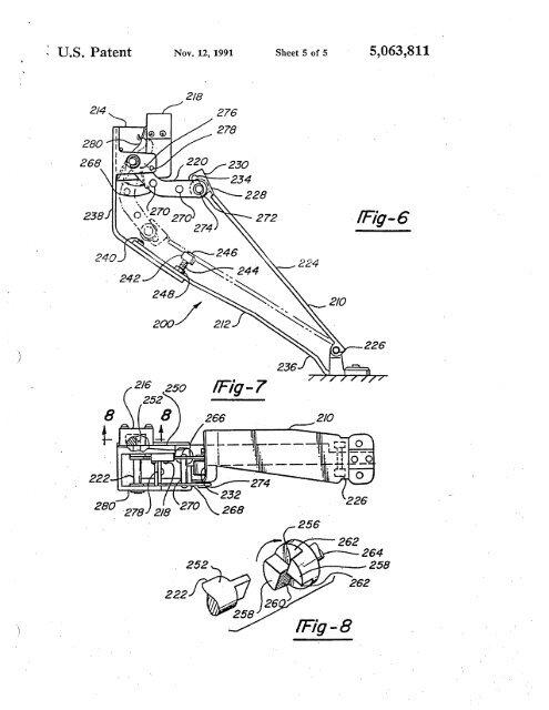
, u.s. Patent Nov. 12, 1991 Sheet 5 <strong>of</strong> 5 5,063,8112/8fFig-6248200/2268l-/Fig -7222 274280222fFg-8262 264258262
1ACCELERATOR PEDAL ASSEMBLYTECHNICAL FIELDThe present <strong>in</strong>vention relates to accelerator pedalassemblies, and more particularly to a floor panmounted electronic accelerator peda assembly <strong>for</strong> vehicles.5,063,811BACKGROUND OF THE INVENTION-Until recent years, the conventional accelerator pedalasembly was mechanical <strong>in</strong> nature <strong>in</strong> that the position<strong>of</strong> the accelerator peda was transferred by mechancalmeas to the 'eng<strong>in</strong>e thottle control. This mechanicamean is usually <strong>in</strong> the <strong>for</strong>m <strong>of</strong> mechanical l<strong>in</strong>ages and 15cables.More recently, with the advent <strong>of</strong> fuel <strong>in</strong>jectionandmore sophiticated and precisely tuned fuel controlsystems, electronic controls have come <strong>in</strong>to popular userather than mechanica controls. With this has been the 20adaptation <strong>of</strong> the electronic accelerator pedal asemblieswhich iIiclude an electronic device <strong>for</strong> <strong>in</strong>dicat<strong>in</strong>gthe pèdal position from its idle position to the fully wideopen throttle position. Typical or such assemblies arethose shown <strong>in</strong> U.S. Pat Nos. 4,335,689; 4,718,380; 254,727,838; 4.831,985; and 4,883,037.However, while such systems may allow more precisecontrol <strong>of</strong> eng<strong>in</strong>e operat<strong>in</strong>g parameters, the electroniccomponentry is more delicate than the predecessormechanical components, and must be protected by 30changes <strong>in</strong> the overal design concept <strong>for</strong> the accelera- FIG. 1 is a side elevation view <strong>of</strong>2nent <strong>in</strong>diCt<strong>in</strong>g pedal position, thereby provid<strong>in</strong>g (i~ ,aprogressive pedal ef<strong>for</strong>t without any momenta <strong>in</strong>creasor decreases <strong>in</strong> voltage output; and (ii) an assemblywhich wil provide the same amount <strong>of</strong> fuel <strong>for</strong> a5 given pedal <strong>in</strong>put regardless <strong>of</strong> pedal position.The <strong>in</strong>vention also contemplates an accelerator pedalasembly which can be <strong>in</strong>stalled as a preadj¡isted completeunit <strong>in</strong>volvig m<strong>in</strong>imum <strong>in</strong>stallation ef<strong>for</strong>t andbe<strong>in</strong>g completely compatible with or as a replacement10 <strong>for</strong> exit<strong>in</strong>g peda asemblies.Furher, tbe <strong>in</strong>vention' contemplates an acceleratorpedal assembly hav<strong>in</strong>g a m<strong>in</strong>imum number <strong>of</strong> dist<strong>in</strong>ctlyseparate and serViceable units, whereby service workca be pedormed quickly and conveniently' on anyone<strong>of</strong> the units without disturb<strong>in</strong>g the <strong>in</strong>stallation <strong>of</strong> therema<strong>in</strong><strong>in</strong>g units.Also, the <strong>in</strong>vention contemplates provid<strong>in</strong>g the accelerator'pedal assembly with an optional pedal bladewhich can <strong>in</strong>teract with mechanical components outside<strong>of</strong> the vehicle cab. The motion <strong>of</strong> the blade canoperate, or be operated by, the same components as thepnma accelertor syste<strong>in</strong>.The above objects and other objects, features, andadvantages '<strong>of</strong> the present <strong>in</strong>vention wil be readily apparentfrom the follow<strong>in</strong>g detailed descnption <strong>of</strong> thebest mode <strong>for</strong> carryig out the <strong>in</strong>vention when taken <strong>in</strong>conjunction with the accompany<strong>in</strong>g draw<strong>in</strong>gs.BRIF DESCRIPTON Of THE DRAWINGSthe electronic acceltorpedal assembly. erator pedal assembly <strong>in</strong> accordance with the presntSpecificaly, the wirg to the electrica components <strong>in</strong>vention;2 is a perspective view <strong>of</strong> the electronic acceler-must be secure from the possibilty <strong>of</strong> chaf<strong>in</strong>g which FIG.wil eventully result <strong>in</strong> elecmcal failure. Thus, the 35 ator pedl asembly <strong>in</strong> accordance with the presentpedal asemblies must not precipitate any motion <strong>in</strong> the <strong>in</strong>vention and show<strong>in</strong>g the same at the idle position;connectig wires themselves, such as shown <strong>in</strong> the elec- FIG. 3 is an exploded view <strong>of</strong> the top portion <strong>of</strong> thetronic pedal assebly <strong>of</strong> U.S. Pat. No. 4,883,037. Fur- accelerator pedlassembly <strong>in</strong> accordance with the presther,one must take care tht the electncal components ent <strong>in</strong>vention'<strong>of</strong> the assembly are placed outside or the hostile e~vi- 40 FIG. 4 is å sectionà view taen substatially alongronient zone ly<strong>in</strong>g between the operator's foot orthe lies 4- <strong>of</strong> FIG. 2; ,accel~rato~ peal and the floor pan <strong>of</strong> the vehicle. This FIG. 5 is a side elevation view <strong>of</strong> the top porton <strong>of</strong>zone.is subjected to, the substances .the oper~tor m.ayget the àccelerator pedal assembly illustrat<strong>in</strong>g the actuationon hi or her shoes such as ga, oil, sat, dirt acid and <strong>of</strong> the idle valdation switch <strong>in</strong> accordance with thethe ~ike. . '. 45 present <strong>in</strong>vention;..LikeWle, niere is a need <strong>for</strong> a. pedal assemb!y ~e- ,FIG. 6 is a side elevation view <strong>of</strong> the' electronic accel-eaily In- eratoI' peda asembly <strong>in</strong> accordace with an alternativesigned ~a S1ngl~ compon~~t whic~ ca bestaledm, the vehi?le as o~gial equipment ~r lI ~ re- emboiment <strong>of</strong>placement <strong>for</strong> orlg¡al equipment and one whih is itslf FIG 7' Ia' f FIGthe present <strong>in</strong>vention;6 h . . rt" cross-see 0 view, e po.en ,iome er mpu s asSUMMARY OF TH INVNTION received with<strong>in</strong> the potentiometer; andservceble <strong>in</strong> bäsic modules or component par. 50 ' tie isnaa p , . VlthCW 0.' t:- St o":<strong>in</strong>g tm hPafa tThe ,present <strong>in</strong>vention is designed to servce theabove-mentioned needs.The present <strong>in</strong>vention' contemplates an electronic 55pedal asembly where<strong>in</strong> thè electnca components arelOcted outside tifthe hostie envionment zone beneaththe acceierator peda.The <strong>in</strong>veition further conteInplates an electronicaccelerator pedal assembly where<strong>in</strong> the electnca wir- 60irig extend<strong>in</strong>g between the electrca components on thepedal assebly to the ma wig haress <strong>of</strong> the vehicleare not caused to move relative to the vehicle cab dur<strong>in</strong>gpedal actuation.The <strong>in</strong>veIition' further, contemplates an electronic 65accelerator peal asembly <strong>in</strong>clud<strong>in</strong>g mean establish<strong>in</strong>ga relationship 'between the rotation or the acceleratorpedal and, the voltage outpui<strong>of</strong> the electnca compo-FIG. 8 is an exploded expanded View or the potentiometer<strong>in</strong>put 'shaft and the potentiometer soket memberwith which it is received, as viewed generally <strong>in</strong>the direction <strong>of</strong>l<strong>in</strong>es8-8'<strong>of</strong>FIG. 7. 'BEST MODE FOR CARYING OUT THINVENTIONThe electronic 'accelerator pedal assembly pedormsthe acCelerator control function <strong>for</strong> avehicle built withan, onboard computer fequirig' pedal position <strong>in</strong>put.is used to operatè electronically controlledand <strong>in</strong> some cas, transmissions.The asembly as seen <strong>in</strong> FIGS. 1 and 2 is adapted toThs <strong>in</strong>puteng<strong>in</strong>esmount<strong>in</strong>to the vehicle <strong>in</strong> place <strong>of</strong> ,an exist<strong>in</strong>g acceleratorpedal or as ong<strong>in</strong>al equipment. To the driver or'opera:tor,itwil'operàte <strong>in</strong>' the' same manner as any
- Page 3 and 4:
TABLE OF AUTHORITIESPaee(s)Altoona
- Page 5 and 6:
United Carbon Co. v. Binney & Smith
- Page 7 and 8:
invalidity under 35 U.S.C: § 103 (
- Page 10 and 11: -- In an Offce Action dated Novembe
- Page 12 and 13: just in case there could be an argu
- Page 14 and 15: -- Conventional, off-the-shelf peda
- Page 16 and 17: Here there is no dispute as to any
- Page 18 and 19: n. "OBVIOUSNESS" MUST BE DETERMIND
- Page 20 and 21: Teleflex's argument is erroneous at
- Page 22 and 23: Exs. 8-10; KSR Main Br. at 23-27).
- Page 24 and 25: elements with no change in their re
- Page 26 and 27: mx::0';:¡:-i
- Page 28: ,e ePlaintiffTeleflex Incorporated
- Page 31 and 32: .. ,). ../ IN THE UNTED STATES PATE
- Page 33 and 34: REMAClais 20-23 remai in ths applic
- Page 35 and 36: Offce Action Summaryo Responsive to
- Page 37 and 38: Serial Number: 09/643,422Page 3Ar.U
- Page 39 and 40: mx:J0-;: .t
- Page 41 and 42: 'u.s. Patent . Oct. 24, 1995 Sheet
- Page 43 and 44: u.s. Patent Oct. 24, 1995 Sheet 3 o
- Page 45 and 46: , ,U .8. Patent Oct. 24, 1995 Sheet
- Page 47 and 48: "/ )1ADJUSTABLE CONTROL PEDALAPPART
- Page 49 and 50: 5adjuster member utizig the guide b
- Page 51 and 52: 5,460,0619porton inboard of the slo
- Page 53 and 54: PATENT NO. :DATEDJNVENTOA(S) : ,UNI
- Page 55 and 56: United States Patent (19)Smith et a
- Page 57 and 58: . u.s. Patent Nov. 12, 1991 Sheet 2
- Page 59: , u.s. Patent Nov. 12, 1991 Sheet 4
- Page 63 and 64: 565,063,811FIG. 1 to the wide-open-
- Page 65 and 66: 5,063,811910'above, the uppermeans-
- Page 67 and 68: "..._.. .~ --"N~Applicant:EngelgauS
- Page 69 and 70: , .Applicant: EngelgauSN: 09/643,42
- Page 71 and 72: -,.J.."(". ,to . ) , PTO/SS/26 (10-
- Page 73 and 74: 5The subject inventionADJUSTABLE PE
- Page 75 and 76: S 3 'as set fort in clai l wherein
- Page 77 and 78: mx::0';:Q)
- Page 79 and 80: --,.ApplicationOfficë Action Summa
- Page 81 and 82: Serial Number: 09/236,975Page 3Ar U
- Page 83 and 84: mx::0-;:co
- Page 85 and 86: ",U.S.S.N 09/236,975 2..,. .~-,!.,0
- Page 87 and 88: US.S.N 09/236,975 4aft directions t
- Page 89 and 90: mx::0';:-io
- Page 91 and 92: Form PTO-1449 U.S. DEPARTMENT OF AT
- Page 93 and 94: L-Sheet -i of -i ==.5FORM l'O.1449
- Page 95 and 96: Sheet -- of -l.. b ~~ C'~ §g.' l:
- Page 97: DECLARATION OF JAMES w: DABNEY and