
Create successful ePaper yourself
Turn your PDF publications into a flip-book with our unique Google optimized e-Paper software.
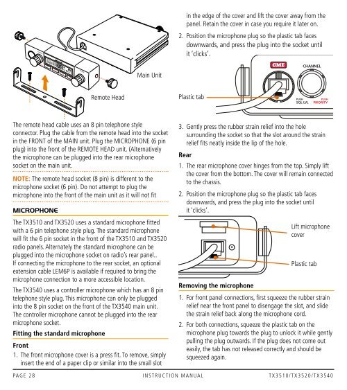
CHANNELin the edge of the cover and lift the cover away from thepanel. Retain the cover in case you require it later on.2. Position the microphone plug so the plastic tab facesdownwards, and press the plug into the socket untilit ‘clicks’.Main UnitCHANNELRemote HeadPlastic tabPUSHSQL LVLPUSHPRIORITYThe remote head cable uses an 8 pin telephone styleconnector. Plug the cable from the remote head into the socketin the FRONT of the MAIN unit. Plug the MICROPHONE (6 pinplug) into the front of the REMOTE HEAD unit. (Alternativelythe microphone can be plugged into the rear microphonesocket on the main unit.Note: The remote head socket (8 pin) is different to themicrophone socket (6 pin). Do not attempt to plug themicrophone into the front of the main unit as it will not fitMicrophoneThe TX3510 and TX3520 uses a standard microphone fittedwith a 6 pin telephone style plug. The standard microphonewill fit the 6 pin socket in the front of the TX3510 and TX3520radio panels. Alternately the standard microphone can beplugged into the microphone socket on radio’s rear panel..If connecting the microphone to the rear socket, an optionalextension cable LEM6P is available if required to bring themicrophone connection to a more accessible location.The TX3540 uses a controller microphone which has an 8 pintelephone style plug. This microphone can only be pluggedinto the 8 pin socket on the front of the TX3540 main unit.The controller microphone cannot be plugged into the rearmicrophone socket.Fitting the standard microphoneFront1. The front microphone cover is a press fit. To remove, simplyinsert the end of a paper clip or similar into the small slot3. Gently press the rubber strain relief into the holesurrounding the socket so that the slot around the strainrelief fits neatly inside the lip of the hole.Rear1. The rear microphone cover hinges from the top. Simply liftthe cover from the bottom. The cover will remain connectedto the chassis.2. Position the microphone plug so the plastic tab facesdownwards, and press the plug into the socket untilit ‘clicks’.Lift microphonecoverPlastic tabRemoving the microphone1. For front panel connections, first squeeze the rubber strainrelief near the front panel to disengage the slot, and slidethe strain relief back along the microphone cord.2. For both connections, squeeze the plastic tab on themicrophone plug towards the plug to unlock it while gentlypulling the plug outwards. If the plug does not come outeasily, the tab has not released correctly and should besqueezed again.PA G E 2 8 I n s t r u c t i o n m a n ua l t X 3 5 1 0 / T X 3 5 2 0 / T X 3 5 4 0