Rex Linkbelt Roller Chain Catalog - Norfolkbearings.com
Rex Linkbelt Roller Chain Catalog - Norfolkbearings.com
Rex Linkbelt Roller Chain Catalog - Norfolkbearings.com
- No tags were found...

Create successful ePaper yourself
Turn your PDF publications into a flip-book with our unique Google optimized e-Paper software.
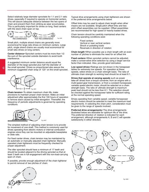
CSelect relatively large diameter sprockets for 1:1 and 2:1 ratiodrives, especially if required to operate on horizontal centers.This will assure adequate distance between the two spans ofchain and prevent them from striking as wear accumulates.This is particularly important for drives on long, fixed centerswith the slack chain span on top.120° +RECOMMENDED NOT RECOMMENDEDFig. 6459Small pitch, multiple strand chains are Fig. 6459RECOMMENDED NOT RECOMMENDED generally moreFig. 6459economical RECOMMENDED Fig. 6459RECOMMENDED for large ratio drives NOT NOT on RECOMMENDED minimum RECOMMENDED centers. Largepitch, single strand chains are usually most economical forsmall ratio drives on long centers.Center distance • Sprocket centers must be more than 1/2the sum of the sprocket outside diameters to avoid toothinterference.A suggested minimum center distance would equal thediameter of the large sprocket plus half the diameter ofthe small sprocket. Drives so proportioned also assure theminimum suggested chain wrap of 120° on the small sprocket.120° +120°120°++TAUT SPANdD + dd 2ddD + d 2DMOVEMENTDDDFig. 6461D + d Fig.Fig.64616461Fig. 6461<strong>Chain</strong> tension • 2To obtain Fig. maximum 6461 chain life, makeD + d 2provisions to maintain proper chain tension. Make an initialadjustment after approximately the first 100 hours of operationto remove slack caused by initial elongation. Thereafter, thefrequency of periodic adjustments is governed by operatingconditions.Fig. 6458Fig. 6457Fig. 6457Fig. 6457Fig. 6457Fig. 6457The simplest method of adjusting chain tension is to providefor movement of one shaft. This method is <strong>com</strong>monly used fordrives operating from electric motors or internal <strong>com</strong>bustionengines since they can be mounted on adjustable baseplatesor slide rails.For fixed center drives, chain tension may be maintained byan automatic or manually adjusted chain tightener. Manuallyoperated chain tighteners must be frequently checked forproper adjustment.The idler sprocket should have a minimum of 17 teeth andshould be located adjacent to the driving sprocket so that atleast 3 teeth are in full engagement with the non-load-carryingspan of chain.If possible, provide enough adjustment of the chain tightenerto permit removal of two pitches of chain.AGTypical drive arrangements using chain tighteners are shownin the preferred drive arrangements below.Offset links may be used to adjust chain length when othermeans are not available. Single-pitch offset links and twopitchoffset assemblies can be supplied. Offset assembliesare re<strong>com</strong>mended for high speed or heavily loaded drives.<strong>Chain</strong> tension should be carefully maintained when thefollowing operating conditions exist:AAAFixed centersVertical or near vertical centersShock or pulsating loadsReversals in direction of rotation<strong>Chain</strong> length • When possible use a chain length with an evennumber of pitches to eliminate the need for an offset linkFixed centers • When sprocket centers cannot be adjusted,make a conservative drive selection by using a larger servicefactor than indicated. Also, provide good lubrication.Low speed drives • Ratings are not shown in the horsepowertables for extremely low speeds. For operation at thesespeeds, select drives on a chain strength basis. The ratio ofultimate chain strength to working load should be at least 6:1.Drives that operate at varying speeds such as powertake-off drives from a torque converter, from an engine with amulti-speed gear transmission, or from a constant horsepower,variable speed electric motor, should be selected on a chainstrength basis. The ratio of ultimate strength to maximumpeak load should not be less than 6:1. The selection shouldbe checked against the horsepower table for sufficient ratingat the normal operating speed.Drives operating from variable speed, variable horsepowerelectric motors should be selected to meet the maximum loadrequirements. In selecting the chain pitch, consideration mustbe given to the range of speeds involved.Preferred drive arrangements • The drive arrangementsillustrated below are desirable for optimum life of the drive.The preferred direction of rotation is indicated for eacharrangement, although arrangements A, B and C will operateBsatisfactorily in either direction.CFFFFEBBBDFig. 6455DDDCCCTAUT SPANTAUT SPANTAUT SPANTAUT SPANMOVEMENTMOVEMENTMOVEMENTMOVEMENTFig. 6458Fig. 6458Fig. 6458Fig. 6458GGGEEEFig. 6455Fig. 6455Fig. 6455Fig. 6455C - 2