Conveyor EngineeringEngineering Re<strong>com</strong>mendationsIn keeping with modern machinery design, roller chains arewidely used for conveyor service because of their appearance,availability, durability, and performance. Precision manufacturingassures long, dependable operation and economical service,while <strong>com</strong>pactness and light weight result in minimum space andpower requirements.Standard <strong>Roller</strong> chains used for conveyor and elevator serviceare the same as those used for power transmission drives. TheDouble Pitch Conveyor chains are similar to the drive chainseries, differing principally in sidebar style.Compared to power transmission applications, chains forconveyor service operate at relatively slow speeds on longercenters and are not exposed to heavy sprocket impact fromhigh velocity, or to the high frequency of joint articulation.Consequently, different methods are used in selecting chains forconveyors than for power transmission service.The procedure for selecting conveyor chains is outlined onpage E-4. Use the following re<strong>com</strong>mendations as a guide whenselecting roller chains for conveyors.<strong>Chain</strong> types • Three general types of roller chains are used forconveyor applications:Standard <strong>Roller</strong> chains with suitable attachments areusually applied where sprocket diameters are restricted andsmoothness of operation is essential. Most sizes are readilyavailable in stainless steel for corrosive conditions.Double Pitch Conveyor chains are more economicalthan Standard <strong>Roller</strong> chains and are available with eitherstandard diameter or large diameter rollers. <strong>Chain</strong>s withstandard diameter rollers are furnished for vertical conveyorsor for applications where the chain slides on the edgeof the sidebars. <strong>Chain</strong>s with large diameter rollers arere<strong>com</strong>mended when it is advantageous to reduce the powerrequired to operate the conveyor.Flat-top chains in numerous styles are available fortransporting containers of all types, small parts, packages,and countless other items through various processingoperations. Top-plates attached to the chain form the carryingsurface.<strong>Chain</strong> pitch • Although conveyor chains are usually selected onthe basis of ultimate strength, it is often necessary to considerchain pitch. <strong>Chain</strong> pitch may govern, or be governed by, the sizeof the carrier or the attachment spacing.Consider short pitch Standard <strong>Roller</strong> chains, 35 through 80,for short conveyors or where smooth operation is required. Fora given sprocket diameter, smaller pitch chains permit a largenumber of sprocket teeth; hence, less chain speed variation.See Chart A, page E-2. For longer conveyors, consider DoublePitch <strong>Roller</strong> chains.Larger pitch standard roller chains, numbers 100 through 160,are used for more heavily loaded conveyors. For long conveyorswith heavy loading, consider Steel Engineering chains. Consult<strong>Rex</strong>nord Industrial <strong>Chain</strong> for specifications.Multiple strand conveyors • When two or more strands ofchains must operate abreast, strands are matched for uniformlength and attachment location. Each 10-foot length is tagged toindicate the proper sequence of assembly. Sprockets should bekeyseated in line with respect to a tooth or tooth space to assurean equal distribution of the load in all strands of chain.182It is not necessary to couple the strands in numerical sequenceunless more than one type of attachment is used in variablespacing.Operating temperature • <strong>Roller</strong> chains may be operatedin moderately elevated temperature zones, as in baking andenameling ovens. The working factors listed in the table on pageE-4 may be used when the chain temperature is below 350° F.Consult <strong>Rex</strong>nord Industrial <strong>Chain</strong> for operation at temperatureabove 350° F. Refer to page E-9 for information regardinglubrication at elevated temperatures.<strong>Chain</strong> joint bearing area • <strong>Chain</strong> joint bearing area is the pindiameter multiplied by the bushing length.Although this value is not directly used in the chain selectionprocedure, it can serve as an indicator of <strong>com</strong>parative wear lifebetween two chains. For this reason, bearing area values areshown in the conveyor chain specification tables, pages D-3to D-6.Catenary tension and chain sag • The formulas applyingto the conveyor layouts on pages E-6 and E-7 do not considercatenary tension since most roller chain conveyors aredesigned to support the return span of chain. However,for short conveyors, it is not un<strong>com</strong>mon or undesirable topermit the return run to hang free. Longer conveyors aresometimes designed so that the major portion of the returnrun is supported, thus allowing the catenary tension in theunsupported section of chain to act as a takeup.When the return run of chain on a long conveyor is unsupported,11 calculate the catenary tension due to chain weight and add itto the chain pull so that the selection will be based on the totalworking load.Catenary tension should not exceed the chain pull and mustbe considered when calculating bearing loads and necessaryshaft diameters, but is not a factor in determining the requiredhorsepower to operate the conveyor.182Fig C-166EE-1
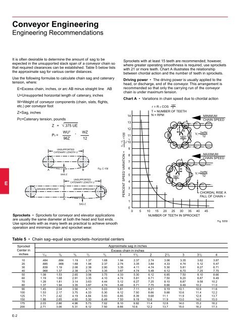
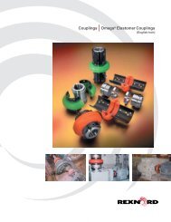
Conveyor EngineeringEngineering Re<strong>com</strong>mendationsEIt is often desirable to determine the amount of sag to beexpected in the unsupported slack span of a conveyor chain sothat required clearances can be established. Table 5 below liststhe approximate sag for various center distances.Use the following formulas to calculate chain sag and catenarytension, where:E=Excess chain, inches, or arc AB minus straight line ABU=Unsupported horizontal length of catenary, inchesW=Weight of conveyor <strong>com</strong>ponents (chain, slats, flights,etc.) per conveyor footZ=Sag, inchesPc=Catenary tension, poundsZ = √.375 UEWU 2 WZ+Pc =96Z 12AADRIVEN DRIVEN SPROCKETUNSUPPORTEDCATENARY LENGTH UUNSUPPORTEDCATENARY LENGTH USAG ZSAG ZAABBUNSUPPORTEDUNSUPPORTEDCATENARY LENGTH U UDRIVER SPROCKETSAG ZSAG ZFig. C-158Fig. C-158Sprockets • Sprockets for conveyor and elevator applicationsare usually the same diameter at both the head and foot ends.Use sprockets with as many teeth as practical to achieve smoothoperation and minimize chain and sprocket wear.BBV 2 - V 1X100Sprockets with at least 15 teeth are re<strong>com</strong>mended; however,where greater operating smoothness is required, use sprocketswith 21 or more teeth. Chart A illustrates the relationshipbetween chordal action and the number of teeth in sprockets.Driving power • The driving power is usually applied to thehead, or discharge, end of the conveyor. This arrangement isre<strong>com</strong>mended so that only R = the PITCH carrying RADIUS run of OF the SPROCKET conveyor WHEELchain is under maximum tension.r = R X COS 180°TChart A • Variations in chain T = NUMBER speed due OF to TEETH chordal actionR = PITCH RADIUS OF SPROCKET WHEEL14N = RPMr = R X COS 180°T13 T = NUMBER OF TEETH A14N = RPMPERCENT SPEED VARIATION =V 213V 2 - V 1 X 100121110PERCENT SPEED VARIATION =987654321V 200121110987654321rr180°T180°TARrrMINIMUMCHAIN SPEEDRV 1 = 2πrN180° 12V 1 = T 2πrN12ARV180°1 = 2πrN12TMAXIMUMMAXIMUM CHAIN SPEEDCHAIN SPEEDV 1 = 2πrN12MINIMUMCHAIN SPEEDCHORDAL RISE CHORDAL AND RISE ANFALL OF CHAIN = R - rFALL OF CHAIN =0 5 10 15 20 25 30 35 40 450 NUMBER 5 10 OF 15 TEETH 20 IN SPROCKET 25 30 35 40 45NUMBER OF TEETH IN SPROCKETRAFig. 5059Table 5 • <strong>Chain</strong> sag–equal size sprockets–horizontal centersSprocketCenter ininchesApproximate sag in inchesExcess chain in inches1/ 16 1/ 8 3/ 8 1/ 2 3/ 4 1 1 1 / 2 2 2 1 / 2 3 3 1 / 2 410 .484 .684 1.19 1.37 1.68 1.94 2.37 2.74 3.06 3.35 3.62 3.8720 .685 .968 1.68 1.94 2.37 2.74 3.35 3.84 4.33 4.74 5.12 5.4730 .839 1.19 2.06 2.38 2.90 3.35 4.11 4.74 5.30 5.81 6.27 6.7140 .968 1.37 2.38 2.74 3.35 3.87 4.74 5.48 6.12 6.70 7.25 7.7550 1.08 1.53 2.65 3.06 3.75 4.33 5.30 6.12 6.85 7.50 8.10 8.6660 1.19 1.68 2.91 3.35 4.10 4.74 5.81 6.71 7.50 8.20 8.87 9.4970 1.28 1.81 3.14 3.63 4.44 5.12 6.27 7.25 8.10 8.87 9.58 10.280 1.37 1.94 3.35 3.87 4.74 5.48 6.71 7.75 8.66 9.49 10.2 11.090 1.45 2.04 3.56 4.11 5.03 5.81 7.11 8.21 9.19 10.1 10.9 11.6100 1.53 2.17 3.75 4.33 5.30 6.12 7.50 8.66 9.68 10.6 11.4 12.2125 1.71 2.42 4.19 4.84 5.93 6.85 8.39 9.68 11.1 11.9 12.8 13.7150 1.88 2.65 4.60 5.30 6.49 7.50 9.19 10.6 11.9 13.0 14.0 15.0175 2.03 2.86 4.96 5.73 7.02 8.10 9.92 11.4 12.8 14.0 15.2 16.2200 2.71 3.06 5.31 6.12 7.50 8.66 10.6 12.2 13.7 15.0 16.2 17.3E-2