978-1-58503-410-9 -- The Fundamentals of SolidWorks 2007
978-1-58503-410-9 -- The Fundamentals of SolidWorks 2007
978-1-58503-410-9 -- The Fundamentals of SolidWorks 2007
- No tags were found...
Create successful ePaper yourself
Turn your PDF publications into a flip-book with our unique Google optimized e-Paper software.
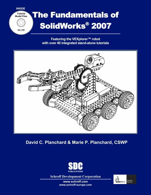
INSIDE:TutorialModel FilesOn CD<strong>The</strong> <strong>Fundamentals</strong> <strong>of</strong><strong>SolidWorks</strong> ® <strong>2007</strong>Featuring the VEXplorer robotwith over 40 integrated stand-alone tutorialsDavid C. Planchard & Marie P. Planchard, CSWPSDCPUBLICATIONSSchr<strong>of</strong>f Development Corporationwww.schr<strong>of</strong>f.comwww.schr<strong>of</strong>f-europe.com
Quick StartCHAPTER 1: QUICK STARTCopyrightedChapter ObjectiveMaterialChapter 1 provides a basic overview <strong>of</strong> theusing <strong>SolidWorks</strong> ® <strong>2007</strong> s<strong>of</strong>tware. If you are new to<strong>SolidWorks</strong>, you should read Chapter 1 in detail andcomplete Lesson 1, Lesson 2, and Lesson 3 in theonline <strong>SolidWorks</strong> Tutorials under Help in the UserMain menu.CopyrightedInterface along with opening and closing files,creating a part, assembly,Materialand drawing.concepts and terminology used throughout this bookChapter 1 introduces you to many <strong>of</strong> the basicoperations <strong>of</strong> <strong>SolidWorks</strong> such as; definitions, startinga <strong>SolidWorks</strong> session, using the User Main menu andOn the completion <strong>of</strong> this chapter, you will beable to:• Comprehend what is <strong>SolidWorks</strong>• Understand and apply basic concepts in <strong>SolidWorks</strong>:• A <strong>SolidWorks</strong> model, features, Base sketch, refining theCopyrighteddesign, associativity, drawings, and geometric constraints• Use the <strong>SolidWorks</strong> User Interface (UI), and CommandManagerMaterial• Start a <strong>SolidWorks</strong> session• Address the following Menus, Task Panes, Commands, and Screens:• <strong>SolidWorks</strong> Resources, Design Library, File Explorer, Search, Right-Click Popupmenus, View Palette, PhotoWorks, Drop-down menus, Fly-outFeatureManager, System feedback, Confirmation Corner, and View Modes• Create a New Part• Create a New Assembly:• Insert Components and MatesCopyrighted• Create a New Assembly Drawing:• Insert four standard views: Front, Top, Right, and Isometric• Insert a simple Bill <strong>of</strong> MaterialsPage 1 - 1
Quick StartWhat isCopyrighted<strong>SolidWorks</strong>?<strong>The</strong> <strong>SolidWorks</strong>application is a mechanical designMaterialautomation s<strong>of</strong>tware package usedto create parts, assemblies, anddrawings which takes advantage <strong>of</strong>the familiar Micros<strong>of</strong>t Windowsgraphical user interface.<strong>SolidWorks</strong> is an easy tolearn design and analysis tool;(COSMOSWorks,CopyrightedCOSMOSFloWorks, andCOSMOSMotion) which makes itpossible for designers to quicklysketch 2D and 3D concepts, create3D parts and assemblies, anddetail 2D drawings.PartAssemblyMaterialIn <strong>SolidWorks</strong>, a part, an assembly, and a drawing are all related as illustrated.<strong>The</strong> book is focused for the new user and assumes that you have little or no workingknowledge <strong>of</strong> <strong>SolidWorks</strong>.Basic Concepts in <strong>SolidWorks</strong>CopyrightedBelow is a list <strong>of</strong> basic concepts in <strong>SolidWorks</strong> to review and to comprehend.<strong>The</strong>se concepts are applicable to all versions <strong>of</strong> <strong>SolidWorks</strong>. All <strong>of</strong> these concepts areaddressed in this book.Material• A <strong>SolidWorks</strong> model. Consists <strong>of</strong> 3D solid geometry in a part or assembly document.<strong>SolidWorks</strong> features start with either a 2D or 3D sketch. You can either import a 2Dor 3D sketch or you can create the sketch in <strong>SolidWorks</strong>.• Features. Individual shapes created by Sketch Entities tools: Lines, Circles,Rectangles, etc. that when combined, creates the part. Features can also be added toassemblies. Some features originate as sketches; other features, such as shells orfillets, are created when you select the appropriate tool or menu command and definethe dimensions or characteristics that you want.Copyrighted• Base sketch. <strong>The</strong> first sketch <strong>of</strong> a part is called the Base sketch. <strong>The</strong> Base sketch is thefoundation for the 3D model. Create a sketch on a default plane or created referenceplane. <strong>The</strong> default planesMaterialare: Front, Top, and Right Plane in the FeatureManagerdesign tree.PartDrawingPage 1 - 2
Quick Start• Refining the design. Adding, editing, or reordering featuresin theCopyrightedFeatureManager design tree. Example: For a partdocument, you can perform the following types <strong>of</strong> featureediting operations:• Edit the definition,Materialthe sketch, or the properties <strong>of</strong> afeature.• Control the access to selected dimensions.• Roll back the part to the state it was in before a selectedfeature was added.• View the parent and child relationships <strong>of</strong> a feature.• Use the feature handles to move and resize features.Copyrighted• Modify the order in which features are reconstructed when the part is rebuilt.• Associativity. A <strong>SolidWorks</strong> model is fully associative. Associativity between parts,sub-assemblies, assemblies, and drawings, assures that changes incorporated in onedocument or drawing view are automatically made to all other related documents anddrawing views.Material• Drawings. Create 2D drawings <strong>of</strong> the 3D solid parts and assemblies which youdesign. Parts, assemblies, and drawings are linked documents. This means that anychange incorporated into the part or assembly changes the drawing document. Adrawing generally consists <strong>of</strong> several views generated from the model. Views canalso be created from existing views. Example: <strong>The</strong> Section or Projected view iscreated from an existing drawing view.• Constraints.Copyrighted<strong>SolidWorks</strong> supports numerous constraints. Constraints are geometricparameters. Apply equations and constraints to your model to capture and maintaindesign intent.Materialrelationships such as Perpendicular, Horizontal, Parallel, Vertical, Coincident,Concentric, etc. Use equations to establish mathematical relationships betweenStarting a <strong>SolidWorks</strong> SessionStart a <strong>SolidWorks</strong> session and familiarize yourself with the <strong>SolidWorks</strong> UserInterface (UI). As you read and perform the tasks in this chapter, you will obtain a senseon howCopyrightedto use this book and the structure. To help you learn the material, short quicktutorials are provided throughout the chapters. Actual input commands or required actionto perform functions in the tutorial is displayed in bold.<strong>SolidWorks</strong> isMaterialdesigned to run on Windows XP Pr<strong>of</strong>essional with a minimum <strong>of</strong> 512MB RAM. If you are using a network license version <strong>of</strong> <strong>SolidWorks</strong>, use the WindowsXP Server Edition.Page 1 - 3
Quick Start<strong>The</strong> book was written using <strong>SolidWorks</strong> Office <strong>2007</strong> on Windows XPPr<strong>of</strong>essional SP2 with a Windows Classic desktop theme. Start a <strong>SolidWorks</strong> session.Copyrighted<strong>The</strong> <strong>SolidWorks</strong> application is located in the Programs folder.Tutorial: Start a <strong>SolidWorks</strong> Session 1-11. Click Start All Programs <strong>SolidWorks</strong> <strong>2007</strong> <strong>SolidWorks</strong><strong>2007</strong> from the Windows taskbar. <strong>The</strong> <strong>SolidWorks</strong> program windowMaterialopens as illustrated. Do not open a document this time. If you donot see this screen, click the <strong>SolidWorks</strong> Resources icon in theTask Pane on the right side <strong>of</strong> the <strong>SolidWorks</strong> Graphics window.2. Read the Tip <strong>of</strong>the Day.CopyrightedDouble-click the<strong>SolidWorks</strong> <strong>2007</strong> icon in theWindows Desktop to start a<strong>SolidWorks</strong> session.Material<strong>SolidWorks</strong> products: <strong>The</strong><strong>SolidWorks</strong> Education Edition,<strong>SolidWorks</strong> Student Edition,<strong>SolidWorks</strong> Student Design Kit,<strong>SolidWorks</strong>, <strong>SolidWorks</strong> Office,and the <strong>SolidWorks</strong> OfficePremium. EachCopyrightedproduct produces<strong>The</strong>re are differenta different header and displaysdifferent functions. This book can be used with all <strong>SolidWorks</strong> products.Material<strong>SolidWorks</strong> User Interface (UI)<strong>The</strong> Task Pane is displayed when a <strong>SolidWorks</strong> session starts. <strong>The</strong> TaskPane can be displayed in the following states: Visible or hidden, Expanded orcollapsed, Pinned or unpinned, Docked or floating.<strong>The</strong> Task Pane contains the following tabs: <strong>SolidWorks</strong> Resources ,CopyrightedDesign Library , File Explorer , Search / , View Palette , DocumentRecovery , and PhotoWorks Items .tab is displayed if your system terminatesunexpectedly with an active document; power outage or abnormal termination.<strong>The</strong> Document RecoveryMaterial<strong>The</strong> PhotoWorks Itemstab is displayed if PhotoWorks is installed.Page 1 - 4
Quick Start<strong>SolidWorks</strong> ResourcesCopyrightedUtilize the left/right arrowsto expand or collapse the Task Pane options. <strong>The</strong> basicMaterial<strong>SolidWorks</strong> Resources menu displays thefollowing default selection tabs: Getting Started,Community, Online Resources, and Tip <strong>of</strong> theDay.or click and drag the boxOther user interfaces are available to bedisplayed; Machine Design, Mold Design, orConsumer Products Design during the initials<strong>of</strong>tware installation selection. <strong>The</strong> book utilizes the MachineDesignCopyrighteduser interface as illustrated.Design LibraryMaterial<strong>The</strong> Design Librarycontains reusable parts,assemblies, and other elements, including library features.<strong>The</strong> Design Library tab contains four defaultselections. Each default selection contains additional subcategories.<strong>The</strong> selections are: Design Library, Toolbox, 3DContentCentral, and <strong>SolidWorks</strong> Content.CopyrightedClick Tools Add-Ins.. <strong>SolidWorks</strong> Toolbox and<strong>SolidWorks</strong> Toolbox Browser to active the <strong>SolidWorks</strong>Toolbox.To access theMaterialDesign Library folders in a non networkenvironment, click Add File Location , enter: C:\ProgramsFiles\<strong>SolidWorks</strong>\data\design library. Click OK.In a network environment, contact your IT department forsystem details.CopyrightedFile ExplorerFile Explorerduplicates Windows Explorer fromyour local computer and displays the following directories:Recent Documents,Materialand Open in <strong>SolidWorks</strong>.Page 1 - 5
Quick StartSearchCopyrightedMicros<strong>of</strong>t Windows Search / is installed with<strong>SolidWorks</strong> and indexes the resources once before searchingbegins, either after installation, or when you initiate the firstsearch.Material<strong>The</strong> <strong>SolidWorks</strong> Search box is displayed in the upperright corner <strong>of</strong> the <strong>SolidWorks</strong> Graphics window. Enter the textor key words to search. Click the drop down arrow to view thelast 10 recent searches.<strong>The</strong> Search tool / in the TaskPane searches the following locations: Alllocations, LocalCopyrightedFiles, Design Library,<strong>SolidWorks</strong> Toolbox, 3D ContentCentral,and Added location.Select any or all <strong>of</strong> the abovelocations. If you do not selectMateriala filelocation, all locations are searched.View PaletteUse the View Palettetool located in the Task Pane toinsert drawing views <strong>of</strong> an active model or click the Browsebutton to locateCopyrightedthe desired model.Click and drag the view from the View Palette into anactive drawing sheet to create the drawing view.Auto RecoveryMaterialis initiated in the System OptionsIf auto recoverysection and the system terminates unexpectedly with an activedocument, the saved information files are available on the Task Pane DocumentRecovery tab.PhotoWorksCopyrightedPhotoWorkscreate photo-realistic images <strong>of</strong><strong>SolidWorks</strong> models. PhotoWorks provides many pr<strong>of</strong>essionalrendering effects. PhotoWorks contains the following defaultfolders: Scene, Materials, Decals, and Lighting. View theMaterial<strong>SolidWorks</strong> Tutorials for additional information.Page 1 - 6
Quick StartClickCopyrightedTools Add-Ins PhotoWorks from the Main menu to active thePhotoWorks feature.Drop-Down MenuMaterial<strong>SolidWorks</strong> takes advantage <strong>of</strong> the familiar Micros<strong>of</strong>t ®Windows ® graphical user interface. Communicate with <strong>SolidWorks</strong>through the drop-down menus or the application toolbars. Acommand is an instruction that informs <strong>SolidWorks</strong> to perform atask.To close a <strong>SolidWorks</strong> drop-down menu, press the Esc key. You can also clickany other part <strong>of</strong> the <strong>SolidWorks</strong> Graphics window, or click another drop-down menu.Copyrighted<strong>The</strong> drop-down menu options perform three basic functions. <strong>The</strong>y are:1. Displays a <strong>SolidWorks</strong> dialog box.2. Submits a command to create or modify your drawing.Material3. Offers an expanded set <strong>of</strong> tools located in the <strong>SolidWorks</strong> Toolbars.Fly-out FeatureManager<strong>The</strong> fly-out FeatureManager design treeallows you to view and select items in thePropertyManager and the FeatureManagerdesign tree at the same time. <strong>The</strong> fly-outFeatureManager provides that ability to selectCopyrighteditems which may be difficult to view or selectfrom the Graphics window. You can hide,modify the transparency <strong>of</strong>, go to, or zoom toselected items. You cannot suppress items or rollMaterialback the build. Throughout the book, you will select commandsand command options from the drop-down menus, fly-outFeatureManager, or from the <strong>SolidWorks</strong> main toolbars.Another method for accessing a command is to use theaccelerator key. Accelerator keys are special keystrokes whichactivates the drop-down menu options. Some commands in theCopyrightedmenu bar and items in the drop-down menus have an underlinedcharacter. Press the Alt key followed by the corresponding key tothe underlined character activates that command or option.MaterialPage 1 - 7
Quick StartRight-Click Pop-up menusCopyrightedRight-click in the Graphics window to display a context-sensitivea list <strong>of</strong> options specifically related to that command. Example: if youright-click your mouse beforeMaterialpicking the first point <strong>of</strong> the Rectangle tool,shortcut menu. If you are in the middle <strong>of</strong> a command, this menu displaysa menu is displayed in the Graphics window. <strong>The</strong> menu displays SketchEntities, Selected Entity, and other Relations and menu options.FeatureManager Design Tree<strong>The</strong> FeatureManager design tree is located on the left side<strong>of</strong> the <strong>SolidWorks</strong> Graphics window. <strong>The</strong> FeatureManagerprovides a summarizeCopyrightedview <strong>of</strong> the active part, assembly, ordrawing. <strong>The</strong> FeatureManager design tree displays the details onhow your part, assembly, or drawing is created.Understand the FeatureManager design tree to troubleshootMaterialyour model. <strong>The</strong> FeatureManager is use extensively throughoutthis book. Expand, collapse, and scroll the FeatureManager designtree.To collapse all items in the FeatureManager, right-click and selectCollapse items, or press the Shift +C keys.Roll back a feature with the rollback bar in theFeatureManager design tree. <strong>The</strong> rollback bar is a yellow and blackCopyrightedline which turns blue when selected. Click and drag the rollbackbar up or down the FeatureManager design tree to step forward orbackward through the regeneration sequence.MaterialYou can save your models with the rollback bar in any location<strong>of</strong> the FeatureManager design tree.<strong>The</strong> FeatureManager design tree and the Graphics windoware dynamically linked. Select sketches, features, drawing views,and construction geometry in either pane. Split the FeatureManagerdesign tree and either display two FeatureManager instances, orcombine the FeatureManagerCopyrighteddesign tree with theConfigurationManager or PropertyManager.MaterialPage 1 - 8
Quick StartMove between the FeatureManager design tree,PropertyManager, ConfigurationManager, and Render ManagerCopyrightedby selecting the tabs at the top <strong>of</strong> the menu.<strong>The</strong> ConfigurationManager is located to the right <strong>of</strong> theFeatureManager. Use the ConfigurationManager to create, select,and view multiple configurations <strong>of</strong> parts and assemblies.MaterialSplit the ConfigurationManager and either display two ConfigurationManagerinstances, or combine the ConfigurationManager with the FeatureManager design tree,PropertyManager, or a third party application that uses the panel. <strong>The</strong> icons in theConfigurationManager denote whether the configuration was created manually or with adesign table.Copyrighted<strong>SolidWorks</strong> provides system feedback bySystem Feedbackattaching a symbol to the mouse pointer cursorarrow. <strong>The</strong> system feedback symbol indicates whatFace Edge Dimension Vertexyou are selecting or what the system is expecting you to select. As you move the mouseMaterialpointer across your model, system feedback is provided to you in the form <strong>of</strong> symbols,riding next to the cursor arrow.Confirmation CornerWhen numerous <strong>SolidWorks</strong> commands are active, a symbolor a set <strong>of</strong> symbols are displayed in the upper right hand corner <strong>of</strong> theGraphics window. This area is called the Confirmation Corner.CopyrightedWhen a sketch is active, the confirmation corner box displaystwo symbols. <strong>The</strong> first symbol is the sketch tool icon. <strong>The</strong> secondsymbol is a large red X. <strong>The</strong>se two symbols supply a visual reminderthat you are in an active sketch. Click the sketch symbol icon to exitMaterialthe sketch and to saves any changes that you made.When other commands are active, the confirmation corner boxprovides a green check mark and a large red X. Use the green checkmark to execute the current command. Use the large red X to cancelthe command.CopyrightedMaterialPage 1 - 9
Quick StartView ToolbarCopyrighted<strong>SolidWorks</strong> provides the user withnumerous view options from the Viewtoolbar. <strong>The</strong> view options are from left to right: Previous View, Zoomto Fit, Zoom to Area, Zoom to Selection, Rotate View, Pan, 3DMaterialDrawing View, Standard Views;(Normal To, Front, Back, Left,Right, Top, Bottom, Isometric, Trimetric, Dimetric) , Wireframe,Hidden Line Visible, Hidden Lines Removed, Shaded With Edges,Shaded, Shadows In Shaded Mode, Section View, Real ViewGraphics.CopyrightedCreate a New PartA part is a 3D modelMaterialwhich consists <strong>of</strong> features. What are features?1. Features are geometry building blocks.2. Features add or remove material.3. Features are created from 2D or 3D sketched pr<strong>of</strong>iles or from edges and faces <strong>of</strong>existing geometry.<strong>SolidWorks</strong>provides two modesCopyrightedin theNew <strong>SolidWorks</strong>Document dialog box:Novice and Advanced.<strong>The</strong> Novice Modeis the default mode withthree default templates.<strong>The</strong> AdvancedMode contains access tocreate additionaltemplates. In this book,you will use the AdvancedMode.MaterialAdvanced modeCopyrightedBefore you beginthe tutorials create a<strong>SolidWorks</strong> folder and copy the files from the CD in the book.Use these folders to createMaterialyour models.Page 1 - 10
Quick StartCreate the Stand<strong>of</strong>f PartCopyrightedTutorial: New Part - Stand<strong>of</strong>f 1-2Create a New part named Stand<strong>of</strong>f.1. Click NewMaterialfrom the Standard toolbar.2. Select the Advanced Mode from the New <strong>SolidWorks</strong>Document dialog box. <strong>The</strong> Templates tab is the defaulttab. Part is the default template from the New<strong>SolidWorks</strong> Document dialog box.3. Click OK from the New <strong>SolidWorks</strong> Document dialog box.<strong>The</strong> Part FeatureManager is displayed.Copyrighted<strong>The</strong> Advanced mode remains selected for all newdocuments in the current <strong>SolidWorks</strong> session. <strong>The</strong> Advancedmode setting is saved when you exit <strong>SolidWorks</strong>. <strong>The</strong> default<strong>SolidWorks</strong> installation contains two tabs in the New<strong>SolidWorks</strong> Document dialog box: Templates and Tutorial.Material<strong>The</strong> Templates tab corresponds to the default<strong>SolidWorks</strong> templates. <strong>The</strong> Tutorial tab corresponds to thetemplates utilized in the <strong>SolidWorks</strong> Tutorials.In a <strong>SolidWorks</strong> session, the first system default part filename is named: Part1.<strong>The</strong> system attaches the .sldprt suffix to the created part. <strong>The</strong> second created part in thesame session, increments to the filename: Part2. Part1 is displayed in theFeatureManager. <strong>The</strong> Main menu, Standard toolbar, and CommandManager aredisplayedCopyrightedabove the <strong>SolidWorks</strong> Graphics window. <strong>The</strong> CommandManager is dividedinto the Control Area and an expanded toolbar. Select a Control Area icon to display thecorresponding toolbar. <strong>The</strong> Features icon and Features toolbar are selected by default inthe Part mode.MaterialCopyrighted<strong>The</strong>re are different <strong>SolidWorks</strong> products. <strong>The</strong> <strong>SolidWorks</strong> Education Edition,<strong>SolidWorks</strong> Student Edition, <strong>SolidWorks</strong> Student Design Kit, <strong>SolidWorks</strong>, <strong>SolidWorks</strong>MaterialOffice, and the <strong>SolidWorks</strong> Office Premium. Each product produces a different headerand displays different functions. This book can be used with all <strong>SolidWorks</strong> products.Page 1 - 11
Quick StartSave the Stand<strong>of</strong>f part.Copyrighted4. Click File Save from theMain menu.5. Select the folderVEXplorer Models.Material6. Enter Stand<strong>of</strong>f for the Filename in the VEXplorerModels folder.7. Click Save.Organize parts into filefolders. Copy and use the folders on the CD in the book. Create a separate sub folder foryour solutions.CopyrightedIn a <strong>SolidWorks</strong> application, each part, assembly, and drawing isreferred to as a document.MaterialEach document is displayed in a separateGraphics window.Define the Document Properties.8. Click Options from theStandard toolbar. Click theDocument Properties tab.9. Select ANSI from theDimensioning standard box.Copyrighted10. Click Units.11. Select MMGS (millimeter,gram, second) for Unitsystem.Material12. Select 2 for Length unitsdecimal place. Select 0 forAngular units decimal place.13. Click OK from the Document Properties - Units dialog box.Create the 2D Sketch plane for the part. <strong>The</strong> Sketch plane is the plane on which asketch lies and is configurable through the Sketch Plane PropertyManager. In<strong>SolidWorks</strong>, the name used to describe a 2D or 3D pr<strong>of</strong>ile is called a Sketch.Copyrighted<strong>The</strong> Reference Triad is located in the lower left corner <strong>of</strong> the Graphicswindow. <strong>The</strong> Reference Triad displays the orientation <strong>of</strong> the modelcoordinate axes; (Red-X, Green-Y,Materialand Blue-Z) all times when activated.Page 1 - 12
Quick Start<strong>The</strong> Reference Triad aids you to display how the view orientation is displayed relative tothe Front Plane.CopyrightedCreate a 2D Sketch.14. Click Front Plane from the FeatureManager design tree.This is your Sketch plane for the first feature. This is theBase sketch.Material15. Click Sketch from the Control Area. <strong>The</strong> Sketch toolbaris displayed in the CommandManager.16. Click Circle from the Sketch toolbar. <strong>The</strong> Sketch openson the Front Plane in the Front view by default. <strong>The</strong> CirclePropertyManager is displayed.Copyrightedfeedback symbolMaterial17. Drag the mouse pointer into the Graphicswindow. <strong>The</strong> cursor displays the Circle. <strong>The</strong> center point <strong>of</strong> thecircle is positioned at the Origin. <strong>The</strong> part Origin is displayed in the center <strong>of</strong> theGraphics window. <strong>The</strong> Origin represents the intersection <strong>of</strong> the three default referenceplanes. <strong>The</strong>y are: Front Plane, Top Plane, and Right Plane. <strong>The</strong> positive X-axis ishorizontal and points to the right <strong>of</strong> the Origin in the Front view. <strong>The</strong> positive Y-axisis vertical and points upward in the Front view.<strong>The</strong> Front Plane rotates, and is parallel to the screen. This onlyhappens for your first sketch in a part.Copyrighted18. Click the Origin from the Graphics window. This is the first point<strong>of</strong> the circle. <strong>The</strong> red dot feedback indicates the Origin point location.<strong>The</strong> mouse pointer displays the Coincident to point sketch relationfeedback symbol .Material19. Drag the mouse pointer to the right <strong>of</strong> the Origin.20. Click a position to create the circle.To control the Sketch relation display, click View SketchRelations from the Main menu.Insert aCopyrightedDimension.21. Click Smart Dimension from the Sketch toolbar.22. Click the circumference <strong>of</strong> the circle. <strong>The</strong> cursordisplays the diameter feedback symbol.MaterialPage 1 - 13
Quick Start23. Click a position to place the dimension in the Graphicswindow.Copyrightedfrom the Modify dialog box. <strong>The</strong> circular sketch isMaterial24. Enter 10mm the Modify dialog box. Click the green checkmarkcentered at the Origin.25. Press the f key to fit the sketch to the Graphics window.If your sketch is not correct, select Undo from the Main menu.<strong>The</strong> Extruded Boss/Base feature adds material to a part. <strong>The</strong> Extruded Basefeature is the first feature <strong>of</strong> the Stand<strong>of</strong>f part. An extrusion extends a pr<strong>of</strong>ile along a pathnormal (⊥) to the pr<strong>of</strong>ile plane for some distance. <strong>The</strong> movement along that pathbecomes the solid model. <strong>The</strong> 2Dcircle is sketchedCopyrightedon the Front Plane.Insert an Extruded Boss/BaseFeature.Material26. Click Features from theControl Area.27. Click Extruded Boss/Basefrom the Featurestoolbar. <strong>The</strong> ExtrudePropertyManager is displayed.<strong>The</strong> ExtrudeCopyrightedPropertyManagerdisplays the parameters utilizedto define the feature.28. Select Mid Plane for EndCondition in DirectionMaterial1. <strong>The</strong>Mid Plane End Conditionextrudes the sketch equally onboth sides <strong>of</strong> the Sketch plane.29. Enter 12mm for Depth. <strong>The</strong>Depth defines the distance. Notethe direction <strong>of</strong> the extruderelative to the Origin.Copyrightedcreated and is displayed in theFeatureManager. Extrude1Materialis30. Click OK from the ExtrudePropertyManager. Extrude1 isyour Base feature.Page 1 - 14
Quick StartToCopyrightededit a feature, right-click the desired feature in the FeatureManager. Click EditFeature. <strong>The</strong> PropertyManager is displayed.Display an Isometric view.31. Click IsometricMaterialview from the Reference Triad drop-down list.<strong>The</strong> Extruded Cut feature removes material from a part. <strong>The</strong> ExtrudedCut feature is the second feature <strong>of</strong> the Stand<strong>of</strong>f part. An Extruded Cutextends a pr<strong>of</strong>ile along a path normal (⊥) to the Sketch plane for somedistance and removes material inside or outside the sketch. <strong>The</strong> 2D circle issketched on the front face <strong>of</strong> the Stand<strong>of</strong>f to create a hole.Insert a Sketch.32. ClickCopyrightedthe front face <strong>of</strong> Extrude1 in the Graphics window. <strong>The</strong>selected face in the Graphics window is displayed in green.Extrude1 is highlighted in the FeatureManager.33. Click Sketch from the Control Area. <strong>The</strong> Sketch toolbar isdisplayed in the CommandManager.Material34. Click Circle from the Sketch toolbar.35. Click the Origin . Click a position to the right <strong>of</strong> the Origin.<strong>The</strong> circle is created.Insert a dimension.36. Click Smart Dimension from the Sketch toolbar. Click theCopyrightedcircumference <strong>of</strong> the circle. <strong>The</strong> cursor displays the diameterfeedback symbol. Click a position to place the dimension in theGraphics window.37. Enter 3mm in theMaterialModify dialog box. Click the green checkmark from the Modify dialogbox. <strong>The</strong> circular sketch iscentered at the origin.Insert an Extruded Cut feature.38. Click Features from theControl Area.Copyrighted39. Click Extruded Cutfrom the Features toolbar. <strong>The</strong>Cut-Extrude PropertyManager isdisplayed.MaterialPage 1 - 15
Quick Start40. Select Through All for End Condition in Direction 1.Copyrighted41. Click OK from the Cut-Extrude PropertyManager.Cut-Extrude1 is displayed in the FeatureManager.Edit the color <strong>of</strong> the Stand<strong>of</strong>f part.Material42. Click the Stand<strong>of</strong>f icon from the FeatureManager.43. Click Edit Color from the Standard toolbar. <strong>The</strong> Colorand Optics PropertyManager is displayed.44. Select a color from the Edit Color box as illustrated.45. Click OK from the Color And Optics PropertyManager.Copyrighted47. Double-click the Ø3 dimension.MaterialModify a dimension.46. Double-click the Cut-Extrude1 feature in the FeatureManager.48. Enter 1.00mm in the Modify dialog box.49. Click the green check mark from the Modifydialog box.50. Click Rebuild from the Standard toolbar toupdate the dimensions.51. Press the f key to fit the model to the Graphicswindow.CopyrightedClose the model.52. Click File Close fromthe Main menu.MaterialYou completed theStand<strong>of</strong>f part using the ExtrudedBase/Boss feature with the MidPlane End Condition option. <strong>The</strong>Extruded Cut feature was used tocreate a Through All hole. Youalso applied a color to the partwith the Edit Color tool tocontrol part and feature color andCopyrightedmodified an existing dimension.To edit a sketch, right-clickMaterialthe desired sketch in the FeatureManager. Click Edit Sketch or Edit Sketch Plane.Page 1 - 16
Quick StartCreateCopyrighteda New AssemblyAn assembly is a document that contains two or more parts. An assembly insertedinto another assembly is called a sub-assembly. A part or sub-assembly inserted into anMaterialassembly is called a component. Create the Gear assembly consisting <strong>of</strong> the followingcomponents: Stand<strong>of</strong>f2 and Gear28.Establishing the correct component relationship in an assembly requiresforethought on component interaction. Mates are geometric relations that align and fitcomponents in an assembly. Mates remove degrees <strong>of</strong> freedom from a component. Matesreflect the physical behavior <strong>of</strong> a component in an assembly. <strong>The</strong> components in the Gearassembly utilize Standard Mate types only.Copyrighted<strong>SolidWorks</strong> Help Topics list the rules governing Mate Type valid geometry.Tutorial: New Assembly - Gear 1-3Create a New assembly named Gear. First open the Stand<strong>of</strong>f2 part.Material1. Click Open from the Standard toolbar. Double-click the Stand<strong>of</strong>f2 part from theVEXplorer Models folder. You copied this folder from the CD-ROM in the book.Create a New assembly.2. Click New from the Standard toolbar.3. Double-click the Assembly icon from the New<strong>SolidWorks</strong> Document dialog box. <strong>The</strong> InsertComponentCopyrightedPropertyManager is displayed.PropertyManager is displayedwhen the Start commandMaterialwhen<strong>The</strong> Insert Componentcreating new assembly option boxis checked.Insert the Stand<strong>of</strong>f2 part.4. Click View; check Originsfrom the Main menu.5. Click Stand<strong>of</strong>f2 from thePart/Assembly to Insert box.Copyrighted6. Click the Origin in theGraphics window. Assem1 isdisplayed in theFeatureManager and is fixedMaterialto the Origin, (f).Page 1 - 17
Quick Start7. Click File Save As from the Main menu.Copyrightedcomponent in the Gear assembly and is fixed (f).Material8. Select the VEXplorer Model Save in folder. Enter Gear for File name.9. Click Save. <strong>The</strong> Gear Assembly FeatureManager is displayed. Stand<strong>of</strong>f2 is the firstInsert the Gear28 part.10. Click Insert Component from the Assembly toolbar.<strong>The</strong> Insert Component PropertyManager is displayed.11. Click Browse from the Part/Assembly to Insert box.12. Double-click the Gear28 part from the VEXplorer Modelsfolder. <strong>The</strong>CopyrightedGear28 part is displayed in the Graphics window.Note: Select part for Files <strong>of</strong> type.13. Click a position in the back <strong>of</strong> the Stand<strong>of</strong>f2 component asillustrated.14. Press the f key to fit theMaterialmodel to the Graphics window.15. Click and drag the Gear28 component if required as illustrated.Deactivate the Origins.16. Click View; uncheck Origins from the Main menu.<strong>The</strong> wheel mouse button or middle mouse button controls Zoom In/Out in theGraphics window. Use Ctrl+middle mouse button to Pan. Hold the middle mouse buttondown to rotate the model in the Graphics window.CopyrightedInsert a Concentric Mate between the Stand<strong>of</strong>f2 and the Gear28 component. AConcentric mate forces two cylindrical faces to become concentric. <strong>The</strong> faces can movealong the common axis, but cannot be moved away from this axis.MaterialInsert a Concentric Mate.17. Click Mate from the Assembly toolbar. <strong>The</strong> MatePropertyManager is displayed.18. Click the inside cylindrical hole face <strong>of</strong> Gear28 asillustrated. Note: the mouse pointer icon feedback for theselected face. Face@Gear28 is displayed in the MateSelectionsCopyrightedbox.MaterialPage 1 - 18
Quick Start19. Click the long cylindrical face <strong>of</strong> the Stand<strong>of</strong>f2component.Copyrighted<strong>The</strong> two selected faces are displayed inpositioned concentric to the Gear28 hole.Materialthe Mate Selections box. <strong>The</strong> Concentric Mate type isselected by default. <strong>The</strong> Stand<strong>of</strong>f2 component is20. Click the green check mark from the Pop-upMate box. Concentric1 is created.21. Click and drag Gear28 left to right. <strong>The</strong> Gear28 translates inand out along the Stand<strong>of</strong>f2 component.Position the mouse pointer in the middle <strong>of</strong> the face to selectthe entire face. Do not position the mouse pointer near the edge<strong>of</strong> a face.CopyrightedIf you select a wrong face or edge during the mate process,right-click in the Mate Selections box and select ClearSelections.MaterialIf you delete a and then recreate it, the numberswill be in a different order.A Coincident mate forces two planar faces to becomecoplanar. <strong>The</strong> faces can move along one another, but cannotbe pulled apart. A Distance mate separates two planar facesby a specified value.CopyrightedInsert a Distance Mate.22. If required, clear the Mate Selections box.23. Click the front circular face <strong>of</strong> the Gear28 component asillustrated.Material24. Click the front circular face <strong>of</strong> the Stand<strong>of</strong>f2component as illustrated. <strong>The</strong> two selected facesare displayed in the Mate Selection box.Coincident is selected by default.25. Click Distance from the Mate pop-up box.CopyrightedMaterialPage 1 - 19
Quick Start26. Enter 5mm for Distance. Click the Flip Dimension button if required.Copyrighted27. Click the Green Check mark from the Mate pop-upbox. Distance1 is created.28. Click OK from theMaterialPropertyManager.29. Press the f key to fit the model to the Graphics window.30. Click Isometric view . Expand the Mates folder from theFeatureManager. View the created mates.31. Click Save .32. Click and drag the front circular face <strong>of</strong> Gear28. Gear28 isfree to rotate about the Stand<strong>of</strong>f2 component.Copyrightedkey to Zoom out on the model.MaterialPress the Shift+ z keys to Zoom in on the model. Press the zCreate a New Assembly DrawingA <strong>SolidWorks</strong> drawing displays 2D and 3D views <strong>of</strong> a part or assembly. <strong>The</strong>foundation <strong>of</strong> a <strong>SolidWorks</strong> drawing is the drawing template. Drawing size, drawingstandards, company information, manufacturing, and or assembly requirements, units andother properties are defined in the drawing template. In this section you will use thedefault drawing template.Copyrighted<strong>The</strong> sheet format is incorporated into the drawing template. <strong>The</strong> sheet formatcontains the border, title block information, revision block information, company nameand or logo information, Custom Properties and <strong>SolidWorks</strong> Properties. Because thissection <strong>of</strong> the book is a Quick Start section, you will not address these items at this time.MaterialCustom Properties and <strong>SolidWorks</strong> Properties are shared values betweendocuments. Utilize an A-size Drawing Template with Sheet Format for the Gearassembly drawing.A drawing contains views, geometric dimensioning, and tolerances, notes andother related design information. When a part or assembly is modified, the drawingautomatically updates. When a dimension in the drawing is modified, the part or theassembly is automatically updated.CopyrightedTutorial: New Drawing - Gear 1-4Create a New assembly drawing named Gear. Display theFront, Top, Right, and Isometric views. Utilize theModelView command in the Drawings toolbar.Material1. Click New from the Standard toolbar.Page 1 - 20
Quick Start2. Double-click the Drawing icon from the Templates tab.CopyrightedView PropertyManager is displayed.Material3. Select A-Landscape from the Sheet Format/Size dialog box.4. Click OK from the Sheet Format/Size dialog box. <strong>The</strong> Model5. Click Cancel from the Model View PropertyManager.<strong>The</strong> Draw1 FeatureManager is displayed. Set the Sheet1Properties in the drawing.<strong>The</strong> Model View PropertyManager is displayed if the Startcommand when creating new drawing option is checked.6. Right-click in Sheet1.Copyrighted7. Click Properties. <strong>The</strong> Sheet Properties is displayed. Draw1 is thedefault drawing name. Sheet1 is the default first sheet name. <strong>The</strong>Control Area alternates between Drawings, Sketch, andAnnotations toolbars. <strong>The</strong> Model View PropertyManager is selectedby default.Material8. Select Sheet Scale 1:1.9. Select Third angle for Type <strong>of</strong>projection.10. Click OK from the SheetProperties dialog box. <strong>The</strong> A-Landscape paper is displayed in anew Graphics window. <strong>The</strong> sheetCopyrightedborder defines the drawing size,11″ × 8.5″ or (279.4mm ×215.9mm). <strong>The</strong> Drawings toolbar isdisplayed in theMaterialCommandManager.Set the Document Properties.11. Click Options from the Standards toolbar.12. Click the Document Properties tab.13. Select ANSI for Dimensioning standard.Copyrighted16. Enter 2 for Length units decimal place.Material14. Click Units.15. Select MMGS (millimeters, gram, second) for Unit system.17. Enter 0 for Angular units decimal place.Page 1 - 21
Quick Start18. Click OK from the Document Properties - Units dialog box.CopyrightedDetailing options provide the ability to address; dimensioningstandards, text style, center marks, extension lines, arrow styles,tolerance and precision.Save the drawing.Material19. Click Save . Enter Gear for file name.20. Click Save. <strong>The</strong> Gear drawing FeatureManager is displayed.21. Click Drawings from the Control Area. <strong>The</strong> Drawingstoolbar is displayed.Copyrighted22. Click Model View from the Drawings toolbar.23. Double-click Gear from the Model View PropertyManager.Material<strong>The</strong> Model View PropertyManager is displayed.Insert a Front, Top, Right, and Shaded with Edges Isometric view.24. Click Multiple views from the Number <strong>of</strong> Views box.25. Click *Front, *Top, and *Right from the Orientation box.Note: Isometric view is selected by default.26. Click OK from the Model View PropertyManager. <strong>The</strong>four views are displayed in Sheet1.CopyrightedDrawing View4 PropertyManager is displayed.Material27. Click Yes.28. Click inside the Isometric view boundary in Sheet1. <strong>The</strong>29. Click Shaded WithEdges from theDisplay Style box.30. Click OK from theDrawing View4PropertyManager. Viewthe four created views.Copyrighted31. Click Save .MaterialPage 1 - 22
Quick StartInsert a Bill <strong>of</strong> Material into the Gear assembly drawing.CopyrightedA drawing can contain a table-based Bill <strong>of</strong> Materials oran Excel based Bill <strong>of</strong> Materials, but not both.32. Click Insert Tables Bill <strong>of</strong> Materials from theMain menu. <strong>The</strong> Bill <strong>of</strong> Materials PropertyManager isdisplayed.33. Click inside the Front view, Drawing View1. View themouse pointer icon feedback symbol.34. Click Top level only from the BOM Type box. Accept allother defaults.35. ClickCopyrightedOK from the Bill <strong>of</strong> Materials PropertyManager.Bill <strong>of</strong> Materials as illustrated.Material36. Click a position in the top left corner <strong>of</strong> Sheet1 to position the37. Click OK from the Bill <strong>of</strong>Materials PropertyManager.38. Click inside Sheet1. Bill <strong>of</strong>Material1 is displayed in theFeatureManager. <strong>The</strong> Bill <strong>of</strong>Materials and Title block areincomplete. Complete the Geardrawing later as a homeworkproblem.Copyrighted39. Click Save .40. Click Windows Close Allfrom the Main menu.Material41. Click File Exit from the Main menu to close the<strong>SolidWorks</strong> session. You are finished with Chapter1. Reviewthe <strong>SolidWorks</strong> Tutorials for additional information on parts,assemblies, and drawings.CopyrightedSummaryIn this chapter you learned about a Base sketch, Base feature, Extrude Cutfeatures, refining theMaterialdesign, associativity, drawings, and geometric constraints. Youstarted a <strong>SolidWorks</strong> session, and applied the <strong>SolidWorks</strong> User Interface (UI) andCommandManager.Page 1 - 23
Quick StartYou created the Stand<strong>of</strong>f2 part using the Extruded Base/Boss feature with the MidPlane End ConditionCopyrightedoption in Direction 1. You created an Extruded Cut feature with theThrough All End Condition option to complete the part. You applied dimensions andmodified these dimensions. You applied color to your part using the Color and OpticsPropertyManager.You created the GearMaterialassembly with two components: Stand<strong>of</strong>f2 and Gear28. Youfixed the first inserted component to the Origin. You inserted the second component andthen inserted a Concentric and Distance Mate.You created an assembly drawing with a Front, Top, Right, and Isometric view.You modified the Isometric view with a Shaded with Edges Display Style. In the drawingyou inserted a simple Bill <strong>of</strong> Materials. You have completed the first chapter <strong>of</strong> the book.In Chapter 2, you’ll learn more features and sketching techniques required tocreate a CoverCopyrightedpart and a Gear part used in the VEXplorer model.Key termsMaterial• Associativity. Assures that changes incorporated in one document or drawing view areautomatically made to all other related documents and drawing views.• Base feature. <strong>The</strong> first feature <strong>of</strong> a part is called the Base feature.• Base sketch. <strong>The</strong> first sketch <strong>of</strong> a part is called the Base sketch. <strong>The</strong> Base sketch is thefoundation for the 3D model. Create a 2D sketch on a default plane: Front, Top, andRight in the FeatureManager design tree, or on a created plane.Copyrighted• ConfigurationManager. Located on the left side <strong>of</strong> the <strong>SolidWorks</strong> Graphics windowis a used to create, select, and view multiple configurations <strong>of</strong> parts and assemblies ina document.• Constraints. GeometricMaterialrelations such as Perpendicular, Horizontal, Parallel, Vertical,Coincident, Concentric, etc. Insert constraints to your model to incorporate design• Coordinate system. A system <strong>of</strong> planes used to assign Cartesian coordinates t<strong>of</strong>eatures, parts, and assemblies. Part and assembly documents contain defaultcoordinate systems; other coordinate systems can be defined with reference geometry.Coordinate systems can be used with measurement tools and for exporting documentsto other file formats.Copyrightedintent.• Design intent. Design intent is the intellectual arrangements <strong>of</strong> features anddimensions <strong>of</strong> a design. Design intent governs the relationship between sketches in afeature, features in a part, and parts in an assembly.• Design Library. LocatedMaterialin the Task Pane, the Design Library provides a centrallocation for reusable elements such as parts, assemblies, etc.Page 1 - 24
Quick Start• Drawing. A 2D representation <strong>of</strong> a 3D part or assembly. <strong>The</strong> extension for a<strong>SolidWorks</strong> drawing file name is .SLDDRW.Copyrighted• Document. A file containing a part, assembly, or drawing.• Features. Individual shapes created by Sketch Entities tools: lines, circles, rectangles,etc. that when combined, creates the part. Features are geometry building blocks, theyadd or remove material, and are created from 2D or 3D sketched pr<strong>of</strong>iles or fromMaterialedges and faces <strong>of</strong> existing geometry.• FeatureManager design tree. Located on the left side <strong>of</strong> the <strong>SolidWorks</strong> Graphicswindow and provides an outline view <strong>of</strong> the active part, assembly, or drawing. <strong>The</strong>FeatureManager design tree and the Graphics window are dynamically linked. Youcan select features, sketches, drawing views, and construction geometry in eitherpane.Copyrighted• Extruded Boss/Base. A feature that adds material to a part or an assembly.Material• Fly-out FeatureManager design tree. Allows you to view and select items in thePropertyManager and the FeatureManager design tree at the same time.• Extruded Cut. A feature that removes material from a part or an assembly.• Parameter. A value used to define a sketch or feature, <strong>of</strong>ten a dimension or instance.• Rollback. Suppresses all items below the rollback bar.Check your understandingCopyrighted1: Identify the following feature icon .2: Identify the following feature icon .Material3. Identify the following sketch icon .4. Identify the following sketch icon .5. Identify the number <strong>of</strong> instances in the illustrated model.6. <strong>SolidWorks</strong> provides system feedback by attaching asymbol to the mouse pointer cursor arrow. <strong>The</strong> followingsystem feedback symbolCopyrightedindicates a _____.7. <strong>The</strong> following system feedback symbol indicates a ______.8. In a <strong>SolidWorks</strong> session, the first system default part filename is named ______.9. <strong>SolidWorks</strong> attachesMaterialthe _________ suffix to a part document.10. <strong>SolidWorks</strong> attaches the _______suffix to an assembly document.11. <strong>SolidWorks</strong> attaches the _______ suffix to a drawing document.Page 1 - 25
Quick Start12. Describe the Base feature.Copyrighted15. Describe a component.Material13. Describe the Base sketch.14. Describe an assembly document.16. Describe a Coincident Mate.17. Describe a Distance Mate.18. True or False. Mates remove degrees <strong>of</strong> freedom from a component. Mates reflect thephysical behavior <strong>of</strong> a component in an assembly.19. True or False. <strong>The</strong> FeatureManager provides a summarized view <strong>of</strong> the active part,assembly, or drawing. <strong>The</strong> FeatureManager displays the details on how the part,assembly, or drawingCopyrightedwas created.20. True or False. Constraints are geometric relations such as Perpendicular, Horizontal,Parallel, Vertical, Coincident, and Concentric.21. True or False. <strong>The</strong> (f) symbol next to the component nameMaterialCover_Hole means first component.CopyrightedMaterialCopyrightedMaterialPage 1 - 26


