- Page 2 and 3: Structural Plywood & LVL Design Man
- Page 4 and 5: Table of Contents1 Plywood & LVL -
- Page 6 and 7: 11 Plywood Stressed Skin Panels ...
- Page 8 and 9: Table of FiguresFIGURE 4.1: Plywood
- Page 10 and 11: Part OneProduct Production & Proper
- Page 12 and 13: PeelingAfter conditioning, the logs
- Page 14 and 15: Sanding, Trimming and BrandingAfter
- Page 16 and 17: through to applications where aesth
- Page 18 and 19: 2.7 Identification CodeThe plywood
- Page 20 and 21: 2.10 Non Structural PlywoodsInterio
- Page 22 and 23: 3.5 Veneer QualityVeneer quality us
- Page 24 and 25: the hygroscopic movement of structu
- Page 26 and 27: effective an insulator as the wood
- Page 28 and 29: 5 Structural Plywood - Design Princ
- Page 30 and 31: 12 - 13 40015 - 19 45020 - 25 52026
- Page 32 and 33: TABLE 5.3: Standard Structural Plyw
- Page 34 and 35: TABLE 5.5: Indicative Stiffness Val
- Page 36 and 37: Strength Limit StateStrength LimitS
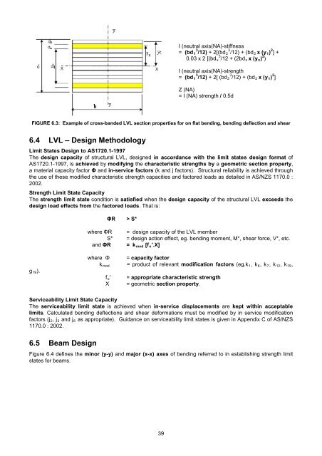
- Page 38 and 39: Application of Structural memberAll
- Page 40 and 41: FIGURE 5.5 shows an I-beam defining
- Page 42 and 43: j 2- Duration of Load Factor for Cr
- Page 44 and 45: Using the theory of parallel axes a
- Page 46 and 47: 6 Structural LVL - Design Principle
- Page 50 and 51: Serviceability Limit State:Calculat
- Page 52 and 53: Strength Limit State:Strength Limit
- Page 54 and 55: Equilibrium Moisture Content (EMC)P
- Page 56 and 57: (c) For shear k 11 = 1.0(d) For com
- Page 58 and 59: Chapter 6 AppendixSlenderness Co-Ef
- Page 60 and 61: FIGURE A6.3: Continuous restraint a
- Page 62 and 63: Stability factor.The stability fact
- Page 64 and 65: 7.4 Structural Plywood Flooring - D
- Page 66 and 67: 5. Critical Load Action EffectsLoad
- Page 68 and 69: 5. Serviceability limit state - Des
- Page 70 and 71: 7.10 Structural Plywood Residential
- Page 72 and 73: Because of the obvious difficulty a
- Page 74 and 75: 1.2 m roof load width)0.25 kPa x 1.
- Page 76 and 77: Concentrated Imposed Load (Q)M max
- Page 78 and 79: 5. Serviceability Limit Stateand [A
- Page 80 and 81: 8 Structural Plywood Webbed Box Bea
- Page 82 and 83: AdhesivesBeams relying only on an a
- Page 84 and 85: 5. Check Beam Stiffness:Check beam
- Page 86 and 87: 1. Initial beam trial size:(a)(b)Fr
- Page 88 and 89: Required nail spacing s = øN j / q
- Page 90 and 91: Figure 8.5 shows a discontinuous pl
- Page 92 and 93: A8Chapter 8 AppendixBending / Compr
- Page 94 and 95: where:A= h3.5 3D .1032 N. mJ12.440.
- Page 96 and 97: FIGURE A8.2: Guide for Selecting In
- Page 98 and 99:
Table A8.6: Unit-Load Deflection Sp
- Page 100 and 101:
9 Structural Plywood Diaphragms & S
- Page 102 and 103:
FIGURE 9.3 shows a plywood panel na
- Page 104 and 105:
The following are the design steps
- Page 106 and 107:
Wind force, w on diaphragm w = 1.86
- Page 108 and 109:
Converted to Limit States CapacityC
- Page 110 and 111:
4. Chord Size and SplicesThe chords
- Page 112 and 113:
Load/Nail (N)Nail Deformation (mm)2
- Page 114 and 115:
• The horizontal force is 1.9 x 2
- Page 116 and 117:
= 5 kN/m v oR = 15/5 = 3 kN/m107
- Page 118 and 119:
ELEVATIONFIGURE 9.12: Shows shear f
- Page 120 and 121:
As previously mentioned the shearwa
- Page 122 and 123:
Assuming the applied racking load t
- Page 124 and 125:
In this instance let the two panels
- Page 126 and 127:
A9 CHAPTER 9 APPENDIXPlate 1Plate 2
- Page 128 and 129:
Plate 7Plate 8Plate 9119
- Page 130 and 131:
REFERENCES CITED:1. Timber Shearwal
- Page 132 and 133:
“nailability” by increasing res
- Page 134 and 135:
(a) (b) (c)FIGURE 10.3: Actual and
- Page 136 and 137:
Re-arranging the torsion equation r
- Page 138 and 139:
The polar moment of area (I p ) of
- Page 140 and 141:
Design Example - Plywood Gusseted P
- Page 142 and 143:
• assuming width of lines paralle
- Page 144 and 145:
hence:where:ΦMj⎡ Ip⎤= (0.8 x1.
- Page 146 and 147:
A10 Chapter 10 AppendixPhotographs
- Page 148 and 149:
MOMENT JOINTSPlate 7Plate 8Plate 9(
- Page 150 and 151:
REFERENCES CITED:1. Investigation o
- Page 152 and 153:
11.2 MaterialsPlywoodPlywood used i
- Page 154 and 155:
FIGURE 11.3: Effective widths of pl
- Page 156 and 157:
Transformed SectionSince the plywoo
- Page 158 and 159:
FIGURE 11.5: Bending stresses in st
- Page 160 and 161:
FIGURE 11.6: Stressed skin panel tr
- Page 162 and 163:
Flexural Deflection Long Term Servi
- Page 164 and 165:
Compression SpliceUsing 17mm F11 st
- Page 166 and 167:
REFERENCES CITED:1. Design & Fabric
- Page 168 and 169:
12 Exotic Structural Forms12.1 Intr
- Page 170 and 171:
displacement between diaphragms eac
- Page 172 and 173:
The section modulus (Z) is:ZZ=Iy1=1
- Page 174 and 175:
FIGURE 12.9: A parabolic arch (not
- Page 176 and 177:
F AFFFASS= (374.4 + 166.4)kN= 540.8
- Page 178 and 179:
12.11 Hypar Design - GeometryTo dev
- Page 180 and 181:
FIGURE 12.16: Reactive force compon
- Page 182 and 183:
12.14 Methodology - Principal Membr
- Page 184 and 185:
Many braced dome geometries exist b
- Page 186 and 187:
θasphere= is the angle subtended b
- Page 188 and 189:
AndNNNxyxyP=L21P=L12P=L33L2P3⎤+
- Page 190 and 191:
• whether or not to force the ply
- Page 192 and 193:
A12Chapter 12 AppendixEXAMPLES OF E
- Page 194 and 195:
EXOTIC STRUCTURAL FORMS DESIGN AIDS
- Page 196 and 197:
Type 1 joints referred to in AS 172
- Page 198 and 199:
FIGURE 13.3: Two and Three member T
- Page 200 and 201:
SECTION 4 : AS 1720.1-1997 : Clause
- Page 202 and 203:
connection load carrying capacity c
- Page 204 and 205:
13.5 Design of Type 1 Nailed Connec
- Page 206 and 207:
The following unfactored loads are
- Page 208 and 209:
nnaa=nnr42=5= 9 rowsThe assumed val
- Page 210 and 211:
13.11 Design of Type 2 Screwed Conn
- Page 212 and 213:
The reasons k 13 and k 14 are not c
- Page 214 and 215:
Type of JointSeasoned TimberUnseaso
- Page 216 and 217:
13.16 Design of Type 2 Bolted Conne
- Page 218 and 219:
where:Δ = Δi +h33j14xh35Q *Qkpfor
- Page 220 and 221:
The exploded view in Figure 13.11 s
- Page 222 and 223:
FIGURE 13.12: Edge, end and bolt sp
- Page 224 and 225:
13.21 Design of Type 2 Coach Screwe
- Page 226 and 227:
REFERENCES CITED:1. AS 1720.1-1997,
- Page 228 and 229:
Plate 3Plate 4219
- Page 230 and 231:
Plate 7Plate 8221
- Page 232 and 233:
14 Noise Control14.1 IntroductionTh
- Page 234 and 235:
The absorption process of a single
- Page 236 and 237:
When it is required to add more tha
- Page 238 and 239:
FIGURE 14.5: Types of cavity wallsT
- Page 240 and 241:
15 Condensation & Thermal Transmiss
- Page 242 and 243:
15.4 Thermal TransmissionThermal tr
- Page 244 and 245:
15.5 Thermal Transmission - Design
- Page 246 and 247:
REFERENCES CITED:1. Condensation, C
- Page 248 and 249:
The early fire hazard test indices
- Page 250 and 251:
ISO 9705 AND AS/NZS 3837These tests
- Page 252 and 253:
General InformationDesign of struct
- Page 254 and 255:
SpeciesAsh, Alpine - Eucalyptus del
- Page 256 and 257:
Results of recent tests organised b
- Page 258 and 259:
FlooringConstructionLVL(Substrates
- Page 260 and 261:
as expressed in the BCA.Species Ave
- Page 262 and 263:
ClosurePlywood Thickness for:Dougla
- Page 264 and 265:
Borers are rarely a problem with st
- Page 266 and 267:
HazardClassH1Exposure Specific serv
- Page 268 and 269:
17.3 Durability and Finishing Appli
- Page 270:
EWPAA MembersPlywood and Laminated