EWPAA Structural Plywood and LVL Design Manual - Engineered ...
EWPAA Structural Plywood and LVL Design Manual - Engineered ...
EWPAA Structural Plywood and LVL Design Manual - Engineered ...
- No tags were found...
You also want an ePaper? Increase the reach of your titles
YUMPU automatically turns print PDFs into web optimized ePapers that Google loves.
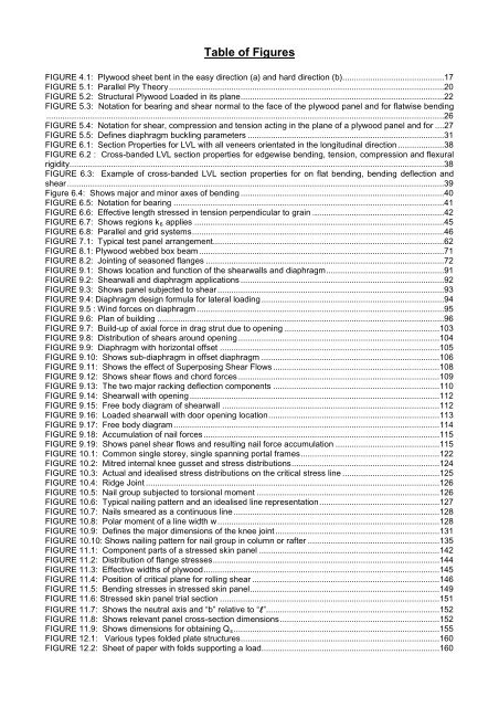
Table of FiguresFIGURE 4.1: <strong>Plywood</strong> sheet bent in the easy direction (a) <strong>and</strong> hard direction (b)............................................17FIGURE 5.1: Parallel Ply Theory .......................................................................................................................20FIGURE 5.2: <strong>Structural</strong> <strong>Plywood</strong> Loaded in its plane ........................................................................................22FIGURE 5.3: Notation for bearing <strong>and</strong> shear normal to the face of the plywood panel <strong>and</strong> for flatwise bending............................................................................................................................................................................26FIGURE 5.4: Notation for shear, compression <strong>and</strong> tension acting in the plane of a plywood panel <strong>and</strong> for ....27FIGURE 5.5: Defines diaphragm buckling parameters .....................................................................................31FIGURE 6.1: Section Properties for <strong>LVL</strong> with all veneers orientated in the longitudinal direction ....................38FIGURE 6.2 : Cross-b<strong>and</strong>ed <strong>LVL</strong> section properties for edgewise bending, tension, compression <strong>and</strong> flexuralrigidity ..................................................................................................................................................................38FIGURE 6.3: Example of cross-b<strong>and</strong>ed <strong>LVL</strong> section properties for on flat bending, bending deflection <strong>and</strong>shear ...................................................................................................................................................................39Figure 6.4: Shows major <strong>and</strong> minor axes of bending ........................................................................................40FIGURE 6.5: Notation for bearing .....................................................................................................................41FIGURE 6.6: Effective length stressed in tension perpendicular to grain .........................................................42FIGURE 6.7: Shows regions k 6 applies ............................................................................................................45FIGURE 6.8: Parallel <strong>and</strong> grid systems .............................................................................................................46FIGURE 7.1: Typical test panel arrangement ....................................................................................................62FIGURE 8.1: <strong>Plywood</strong> webbed box beam ..........................................................................................................71FIGURE 8.2: Jointing of seasoned flanges .......................................................................................................72FIGURE 9.1: Shows location <strong>and</strong> function of the shearwalls <strong>and</strong> diaphragm ...................................................91FIGURE 9.2: Shearwall <strong>and</strong> diaphragm applications ........................................................................................92FIGURE 9.3: Shows panel subjected to shear ..................................................................................................93FIGURE 9.4: Diaphragm design formula for lateral loading ...............................................................................94FIGURE 9.5 : Wind forces on diaphragm ...........................................................................................................95FIGURE 9.6: Plan of building ............................................................................................................................96FIGURE 9.7: Build-up of axial force in drag strut due to opening ...................................................................103FIGURE 9.8: Distribution of shears around opening .......................................................................................104FIGURE 9.9: Diaphragm with horizontal offset ...............................................................................................105FIGURE 9.10: Shows sub-diaphragm in offset diaphragm .............................................................................106FIGURE 9.11: Shows the effect of Superposing Shear Flows ........................................................................108FIGURE 9.12: Shows shear flows <strong>and</strong> chord forces .......................................................................................109FIGURE 9.13: The two major racking deflection components ........................................................................110FIGURE 9.14: Shearwall with opening ............................................................................................................112FIGURE 9.15: Free body diagram of shearwall ..............................................................................................112FIGURE 9.16: Loaded shearwall with door opening location ..........................................................................113FIGURE 9.17: Free body diagram ...................................................................................................................114FIGURE 9.18: Accumulation of nail forces ......................................................................................................115FIGURE 9.19: Shows panel shear flows <strong>and</strong> resulting nail force accumulation .............................................115FIGURE 10.1: Common single storey, single spanning portal frames ............................................................122FIGURE 10.2: Mitred internal knee gusset <strong>and</strong> stress distributions ................................................................124FIGURE 10.3: Actual <strong>and</strong> idealised stress distributions on the critical stress line ..........................................125FIGURE 10.4: Ridge Joint ...............................................................................................................................126FIGURE 10.5: Nail group subjected to torsional moment ...............................................................................126FIGURE 10.6: Typical nailing pattern <strong>and</strong> an idealised line representation ....................................................127FIGURE 10.7: Nails smeared as a continuous line .........................................................................................128FIGURE 10.8: Polar moment of a line width w ................................................................................................128FIGURE 10.9: Defines the major dimensions of the knee joint .......................................................................131FIGURE 10.10: Shows nailing pattern for nail group in column or rafter .........................................................135FIGURE 11.1: Component parts of a stressed skin panel ..............................................................................142FIGURE 11.2: Distribution of flange stresses ..................................................................................................144FIGURE 11.3: Effective widths of plywood ......................................................................................................145FIGURE 11.4: Position of critical plane for rolling shear .................................................................................146FIGURE 11.5: Bending stresses in stressed skin panel ..................................................................................149FIGURE 11.6: Stressed skin panel trial section ...............................................................................................151FIGURE 11.7: Shows the neutral axis <strong>and</strong> “b” relative to “”...........................................................................152FIGURE 11.8: Shows relevant panel cross-section dimensions .....................................................................152FIGURE 11.9: Shows dimensions for obtaining Q s .........................................................................................155FIGURE 12.1: Various types folded plate structures ......................................................................................160FIGURE 12.2: Sheet of paper with folds supporting a load .............................................................................160


