Download PDF - Intel
Download PDF - Intel
Download PDF - Intel

Create successful ePaper yourself
Turn your PDF publications into a flip-book with our unique Google optimized e-Paper software.
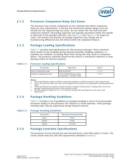
Package Mechanical Specifications2.1.2 Processor Component Keep-Out ZonesThe processor may contain components on the substrate that define componentkeep-out zone requirements. A thermal and mechanical solution design must notintrude into the required keep-out zones. Do not contact the Test Pad Area withconductive material. Decoupling capacitors are typically mounted to either the topsideor land-side of the package substrate. See Figure 2-2 and Figure 2-3 for keep-outzones. The location and quantity of package capacitors may change due tomanufacturing efficiencies but will remain within the component keep-in.2.1.3 Package Loading Specifications.Table 2-1 provides load specifications for the processor package. These maximumlimits should not be exceeded during heatsink assembly, shipping conditions, orstandard use condition. Exceeding these limits during test may result in componentfailure. The processor substrate should not be used as a mechanical reference or loadbearingsurface for thermal solutions.Table 2-1.Processor Loading SpecificationsParameter Maximum NotesStatic Compressive Load 890 N [200 lbf] 1, 2, 3Dynamic Compressive Load1779 N [400 lbf] [max staticcompressive + dynamic load]1, 3, 4Notes:1. These specifications apply to uniform compressive loading in a direction normal to the processor IHS.2. This is the maximum static force that can be applied by the heatsink and Independent Loading Mechanism(ILM).3. These specifications are based on limited testing for design characterization. Loading limits are for thepackage constrained by the limits of the processor socket.4. Dynamic loading is defined as an 11 ms duration average load superimposed on the static loadrequirement.2.1.4 Package Handling GuidelinesTable 2-2 includes a list of guidelines on package handling in terms of recommendedmaximum loading on the processor IHS relative to a fixed substrate. These packagehandling loads may be experienced during heatsink removal.Table 2-2.Package Handling GuidelinesParameterShearTensileTorqueMaximum Recommended70 lbs25 lbs35 in.lbs2.1.5 Package Insertion SpecificationsThe processor can be inserted into and removed from a LGA1366 socket 15 times. Thesocket should meet the LGA1366 requirements detailed in Section 5.<strong>Intel</strong> ® Xeon ® Processor C5500/C3500 Series and LGA1366 SocketAugust 2010Thermal/Mechanical Design GuideOrder Number: 323107-002US 15