Download PDF - Intel
Download PDF - Intel
Download PDF - Intel

Create successful ePaper yourself
Turn your PDF publications into a flip-book with our unique Google optimized e-Paper software.
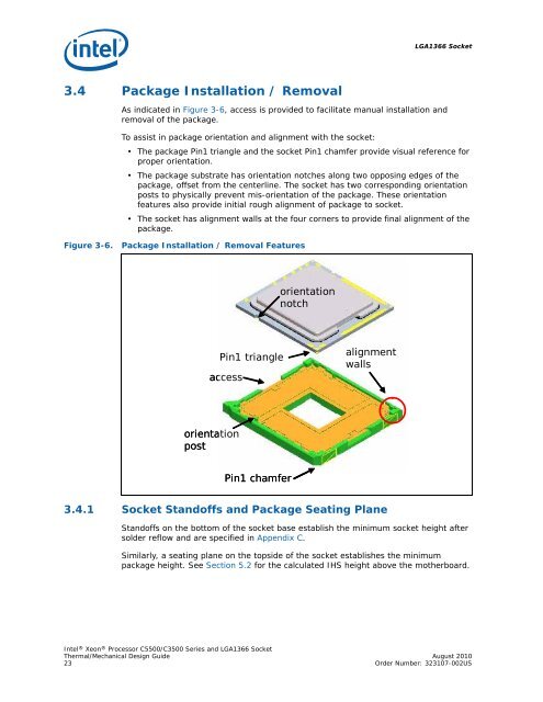
LGA1366 Socket3.4 Package Installation / RemovalAs indicated in Figure 3-6, access is provided to facilitate manual installation andremoval of the package..Figure 3-6.To assist in package orientation and alignment with the socket:• The package Pin1 triangle and the socket Pin1 chamfer provide visual reference forproper orientation.• The package substrate has orientation notches along two opposing edges of thepackage, offset from the centerline. The socket has two corresponding orientationposts to physically prevent mis-orientation of the package. These orientationfeatures also provide initial rough alignment of package to socket.• The socket has alignment walls at the four corners to provide final alignment of thepackage.Package Installation / Removal FeaturesorientationnotchPin1 triangleaccessalignmentwallsorientationpostPin1 chamfer3.4.1 Socket Standoffs and Package Seating PlaneStandoffs on the bottom of the socket base establish the minimum socket height aftersolder reflow and are specified in Appendix C.Similarly, a seating plane on the topside of the socket establishes the minimumpackage height. See Section 5.2 for the calculated IHS height above the motherboard.<strong>Intel</strong> ® Xeon ® Processor C5500/C3500 Series and LGA1366 SocketThermal/Mechanical Design Guide August 201023 Order Number: 323107-002US