Reference Manual BioTrak Datalink and Gas ... - Biodownloads
Reference Manual BioTrak Datalink and Gas ... - Biodownloads
Reference Manual BioTrak Datalink and Gas ... - Biodownloads
- No tags were found...

Create successful ePaper yourself
Turn your PDF publications into a flip-book with our unique Google optimized e-Paper software.
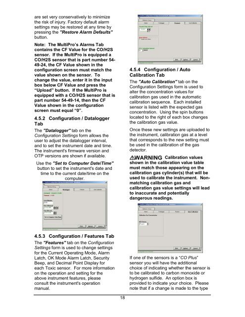
are set very conservatively to minimizethe risk of injury. Factory default alarmsettings may be restored at any time bypressing the "Restore Alarm Defaults"button.Note: The MultiPro’s Alarms Tabcontains the CF Value for the CO/H2Ssensor. If the MultiPro is equipped aCO/H2S sensor that is part number 54-49-24, the CF Value shown in theconfiguration screen must match thevalue shown on the sensor. Tochange the value, enter it in the inputbox below CF Value <strong>and</strong> press the“Upload” button. If the MultiPro isequipped with a CO/H2S sensor that ispart number 54-49-14, then the CFValue shown in the configurationscreen must equal “0”.4.5.2 Configuration / DataloggerTabThe "Datalogger" tab on theConfiguration Settings form allows theuser to adjust the datalogger interval,<strong>and</strong> to set the instrument date <strong>and</strong> time.The instrument's firmware version <strong>and</strong>OTP versions are shown if available.Use the "Set to Computer Date/Time"button to set the instrument's date <strong>and</strong>time to the current date/time on thecomputer.4.5.4 Configuration / AutoCalibration TabThe "Auto Calibration" tab on theConfiguration Settings form is used toalter the concentration values forcalibration gas used in the automaticcalibration sequence. Each installedsensor is listed with the expected gasconcentration. Using the spin buttonslocated to the right of each box changesthe calibration gas value.Once these new settings are uploaded tothe instrument, calibration gas at a levelthat corresponds to the new setting mustbe used in the calibration of the gasdetector.Calibration valuesshown in the calibration value tablemust match those appearing on thecalibration gas cylinder(s) that will beused to calibrate the instrument. Nonmatchingcalibration gas <strong>and</strong>calibration gas value settings will leadto inaccurate <strong>and</strong> potentiallydangerous readings.4.5.3 Configuration / Features TabThe "Features" tab on the ConfigurationSettings form is used to change settingsfor the Current Operating Mode, AlarmLatch, OK Mode Alarm Latch, SecurityBeep, <strong>and</strong> Decimal Point Display foreach Toxic sensor. For more informationon the operation <strong>and</strong> setting for theabove instrument features, pleaseconsult the instrument's operationmanual.If one of the sensors is a “CO Plus”sensor you will have the additionalchoice of indicating whether the sensor isto be calibrated to carbon monoxide orhydrogen sulfide. An option box isprovided to indicate your choice. Pleasenote that if a change is made to the type18