FMDR Technical Handbook.pdf - Omni Metalcraft Corp.
FMDR Technical Handbook.pdf - Omni Metalcraft Corp.
FMDR Technical Handbook.pdf - Omni Metalcraft Corp.

You also want an ePaper? Increase the reach of your titles
YUMPU automatically turns print PDFs into web optimized ePapers that Google loves.
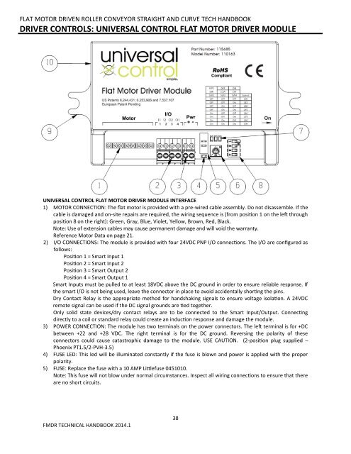
FLAT MOTOR DRIVEN ROLLER CONVEYOR STRAIGHT AND CURVE TECH HANDBOOKDRIVER CONTROLS: UNIVERSAL CONTROL FLAT MOTOR DRIVER MODULEUNIVERSAL CONTROL FLAT MOTOR DRIVER MODULE INTERFACE1) MOTOR CONNECTION: The flat motor is provided with a pre-wired cable assembly. Do not disassemble. If thecable is damaged and on-site repairs are required, the wiring sequence is (from position 1 on the left throughposition 8 on the right): Green, Gray, Blue, Violet, Yellow, Brown, Red, Black.Note: Use of extension cables may cause permanent damage and will void the warranty.Reference Motor Data on page 21.2) I/O CONNECTIONS: The module is provided with four 24VDC PNP I/O connections. The I/O are configured asfollows:Position 1 = Smart Input 1Position 2 = Smart Input 2Position 3 = Smart Output 2Position 4 = Smart Output 1Smart Inputs must be pulled to at least 18VDC above the DC ground in order to ensure reliable response. Ifthe smart I/O is not being used, leave the connector in place to avoid accidentally shorting the pins.Dry Contact Relay is the appropriate method for handshaking signals to ensure voltage isolation. A 24VDCremote signal can be used if the DC signal grounds are tied together.Only solid state devices/dry contact relays are to be connected to the Smart Input/Output. Connectingdirectly to a coil or standard relay could create an induction response and damage the module.3) POWER CONNECTION: The module has two terminals on the power connectors. The left terminal is for +DCbetween +22 and +28 VDC. The right terminal is for the DC ground. Reversing the polarity of theseconnectors could cause catastrophic damage to the module. USE CAUTION. (2-position plug supplied –Phoenix PT1.5/2-PVH-3.5)4) FUSE LED: This led will be illuminated constantly if the fuse is blown and power is applied with the properpolarity.5) FUSE: Replace the fuse with a 10 AMP Littlefuse 0451010.Note: This fuse will not blow under normal circumstances. Inspect all wiring connections to ensure that thereare no short circuits.<strong>FMDR</strong> TECHNICAL HANDBOOK 2014.138