Actuator Guide - Norgren Pneumatics. Motion Control Equipment ...
Actuator Guide - Norgren Pneumatics. Motion Control Equipment ...
Actuator Guide - Norgren Pneumatics. Motion Control Equipment ...

Create successful ePaper yourself
Turn your PDF publications into a flip-book with our unique Google optimized e-Paper software.
pressure build up would be slow,<br />
as the only path would be back<br />
past the cushion screw.<br />
High mass loads, operated at<br />
3<br />
2 1<br />
high speed with long stroke<br />
cylinders, may need special<br />
4<br />
circuitry to provide cushioning. 6<br />
See (Figure 40). This circuitry<br />
5<br />
switches in a pre set restrictor to Figure 40:<br />
start slowing the cylinder down<br />
before the normal cushioning is<br />
External cushioned circuit<br />
engaged. Sometimes it is necessary to control a cylinder at a<br />
variety of speeds selected at different points in the stroke. For<br />
this, valve and flow regulator branches can be set up and<br />
switched in to operation either singly or in combination to<br />
provide the speed required.<br />
17<br />
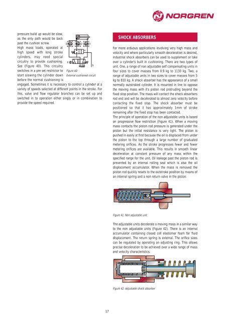
SHOCK ABSORBERS<br />
For more arduous applications involving very high mass and<br />
velocity and where particularly smooth deceleration is desired,<br />
industrial shock absorbers can be used to supplement or take<br />
over a cylinder’s built in cushioning. There are two types of<br />
unit. One, a range of non adjustable self compensating units in<br />
four sizes to cover masses from 0.9 kg to 1130 kg. Two, a<br />
range of adjustable units in two sizes to cover masses from 5<br />
kg to 810 kg. A shock absorber has the appearance of a small<br />
normally outstroked cylinder. It is mounted in line to oppose<br />
the moving mass with it’s piston rod protruding beyond the<br />
fixed stop position. The mass will contact the shock absorbers<br />
rod end and will be decelerated to almost zero velocity before<br />
contacting the fixed stop. The shock absorber must be<br />
positioned so that it has approximately 1mm of stroke<br />
remaining after the fixed stop has been contacted.<br />
The principle of operation of the non adjustable units is based<br />
on progressive flow restriction (Figure 41). When a moving<br />
mass contacts the piston rod pressure is generated under the<br />
piston but the initial resistance is very light. The piston is<br />
pushed in easily at first because the oil is displaced from under<br />
the piston to the top through a large number of graduated<br />
metering orifices. As the stroke progresses fewer and fewer<br />
metering orifices are available. This results in smooth linear<br />
deceleration at constant pressure of any mass within the<br />
specified range for the unit. Oil leakage past the piston rod is<br />
prevented by an internal rolling seal which is also the oil<br />
displacement accumulator. When the mass is removed the<br />
piston rod quickly resets to the outstroke position by means of<br />
an internal spring and a non return valve in the piston.<br />
Figure 41: Non adjustable unit<br />
The adjustable units decelerate a moving mass in a similar way<br />
to the non adjustable units (Figure 42). There is an internal<br />
accumulator containing closed cell elastomer foam for fluid<br />
displacement. The return spring is external. The orifice sizes<br />
can be regulated by operating an adjusting ring. This allows<br />
precise deceleration to be achieved over a wide range of mass<br />
and velocity characteristics.<br />
Figure 42: Adjustable shock absorber