Actuator Guide - Norgren Pneumatics. Motion Control Equipment ...
Actuator Guide - Norgren Pneumatics. Motion Control Equipment ...
Actuator Guide - Norgren Pneumatics. Motion Control Equipment ...

You also want an ePaper? Increase the reach of your titles
YUMPU automatically turns print PDFs into web optimized ePapers that Google loves.
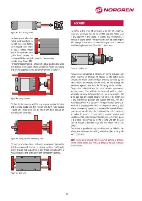
Figure 61: Non-rotating VDMA<br />
the bearing and when the<br />
rod is outstroked twist in<br />
the rod can occur. Within<br />
the Compact range there<br />
is also a guided model<br />
which incorporates twin<br />
guide bars running in<br />
bearings within the extruded Figure 62: Compact guided<br />
cylinder body (Figure 62).<br />
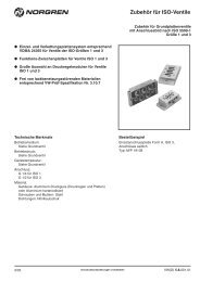
For higher loads there is a choice of add on guide block units<br />
with slide or roller guides. These provide non rotational guiding<br />
and greater support against bending moments (Figure 63).<br />
Figure 63: ISO guide block<br />
For low friction running and the best support against bending<br />
and torsional loads, use the version with twin roller guides<br />
(Figure 64). These units can be fitted with twin passive or<br />
active locking cartridges.<br />
Figure 64: ISO guide block with locking units<br />
For precise actuation, linear slide units incorporate high quality<br />
slide bearings which provide exceptional torsional rigidity with<br />
a twin through-rod layout (Figure 65). These units also offer a<br />
magnetic piston and a choice of port connection positions.<br />
Figure 65: Slide unit<br />
23<br />
LOCKING<br />
For safety in the event of air failure or as part of a machine<br />
sequence, a cylinder may be required to stop and hold a load<br />
at any position in the stroke. To satisfy this requirement, a<br />
passive or active piston rod locking unit can be used (Figure<br />
66). A range of these add on units is designed to suit ISO and<br />
ISO/VDMA cylinders from 12mm to 125mm bore.<br />
Figure 66: Locking unit<br />
The passive units contain a normally-on spring activated lock<br />
which requires air pressure to release it. The active units<br />
contain a normally sprung off lock which is activated by the<br />
application of air pressure. In both types, the lock clamps the<br />
piston rod against loads up to the full rating for the cylinder.<br />
The passive locking unit can be connected with a permanent<br />
pressure supply. This will hold the brake off and the cylinder<br />
will stroke normally. In the event of a failure of the supply, a fail<br />
to the safe lock-on position occurs. This will lock the piston rod<br />
at any intermediate position and support the load. Part of a<br />
machine sequence may consist of a long stroke cylinder that is<br />
required to progressively move a component under a tool<br />
where an assembly operation is repeated in several different<br />
locations. At each location the position of the piston rod must<br />
be locked to prevent it from drifting against varying load<br />
conditions. If an active lock cylinder is used, each time it stops<br />
at a location, the air supply to the locking unit can then be<br />
applied through a suitable valve and the piston rod will be<br />
locked.<br />
Twin active or passive locking cartridges can be added to the<br />
roller guide unit where the locking action is applied to the guide<br />
bars (Figure 64).<br />
Note: These units should not be used to achieve a braking<br />
action on the piston rod. They are designed to give a locking<br />
function only.