Actuator Guide - Norgren Pneumatics. Motion Control Equipment ...
Actuator Guide - Norgren Pneumatics. Motion Control Equipment ...
Actuator Guide - Norgren Pneumatics. Motion Control Equipment ...

Create successful ePaper yourself
Turn your PDF publications into a flip-book with our unique Google optimized e-Paper software.
A right angle mounting allows the carriages of two rodless<br />
cylinders to be joined to provide movement in two planes.<br />
Other mounting arrangements not illustrated include, a<br />
secondary free running carriage style ‘W’ which can be fixed to<br />
the opposite side of the cylinder. This can be connected to the<br />
main carriage by a side mounting plate style ‘UW’. Also an end<br />
plate kit for mounting shock absorbers.<br />
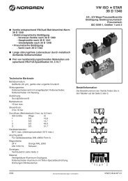
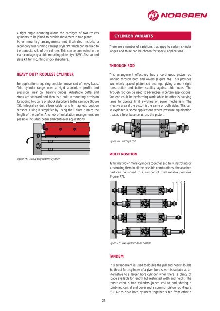
HEAVY DUTY RODLESS CYLINDER<br />
For applications requiring precision movement of heavy loads.<br />
This cylinder range uses a rigid aluminium profile and<br />
precision linear ball bearing guides. Adjustable buffer end<br />
stops are standard and there is a built in mounting provision<br />
for adding two pairs of shock absorbers to the carriage (Figure<br />
75). Integral conduit allows cable runs to magnetic position<br />
sensors. Fixing is simplified by using the T slots running the<br />
length of the profile. A variety of installation arrangements are<br />
possible including beam and cantilever applications.<br />
Figure 75: Heavy duty rodless cylinder<br />
25<br />
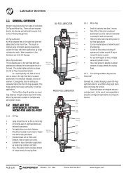
CYLINDER VARIANTS<br />
There are a number of variations that apply to certain cylinder<br />
ranges and these can be chosen for special applications.<br />
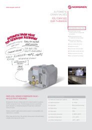
THROUGH ROD<br />
This arrangement effectively has a continuous piston rod<br />
running through both end covers (Figure 76). This provides<br />
two widely spaced piston rod bearings giving a more rigid<br />
construction and better stability against side loads. The<br />
through rod can be used to advantage in certain applications.<br />
One end could be performing work while the other is carrying<br />
cams to operate limit switches or some mechanism. The<br />
effective area of the piston is the same on both sides. This can<br />
be exploited in some applications where pressure equalisation<br />
creates a force balance across the piston.<br />
Figure 76: Through rod<br />
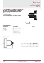
MULTI POSITION<br />
By fixing two or more cylinders together and fully instroking or<br />
outstroking them in all the possible combinations, the attached<br />
load can be moved to a number of fixed reliable positions<br />
(Figure 77).<br />
, y<br />
, y<br />
, y<br />
, y<br />
, y<br />
, y<br />
, y<br />
, y<br />
Figure 77: Two cylinder multi position<br />
TANDEM<br />
1 2 3 4<br />
This arrangement is used to double the pull and nearly double<br />
the thrust for a cylinder of a given bore size. It is suitable as an<br />
alternative to a larger bore cylinder when there is plenty of<br />
space available for length but restricted width and height. The<br />
construction is two cylinders joined end to end sharing a<br />
combined central end cover and a common piston rod (Figure<br />
78). Air to drive both cylinders together is fed from either a