Actuator Guide - Norgren Pneumatics. Motion Control Equipment ...
Actuator Guide - Norgren Pneumatics. Motion Control Equipment ...
Actuator Guide - Norgren Pneumatics. Motion Control Equipment ...

Create successful ePaper yourself
Turn your PDF publications into a flip-book with our unique Google optimized e-Paper software.
INTRODUCTION<br />
Pneumatic actuators, of which cylinders are the most common,<br />
are the devices providing power and movement to automated<br />
systems, machines and processes. A pneumatic cylinder is a<br />
simple, low cost, easy to install device that is ideal for<br />
producing powerful linear movement over a wide range of<br />
velocities, and can be stalled without causing internal damage.<br />
Adverse conditions can be easily tolerated such as high<br />
humidity, dry and dusty environments and repetitive<br />
cleandown with high pressure hoses.<br />
The diameter or bore of a cylinder determines the maximum<br />
force that it can exert and the stroke determines the maximum<br />
linear movement that it can produce. Cylinders are designed to<br />
work at different maximum pressures up to 16 bar. The<br />
pressure actually supplied to a cylinder will normally be<br />
reduced through a pressure regulator to control the thrust to a<br />
suitable level. As an example of cylinder power, a 40mm bore<br />
cylinder working at 6 bar could easily lift an 80kg man.<br />
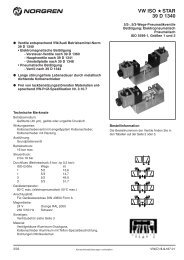
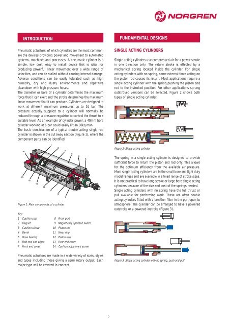
The basic construction of a typical double acting single rod<br />
cylinder is shown in the cut away section (Figure 1), where the<br />
component parts can be identified.<br />
13<br />
14<br />
12<br />
11<br />
Figure 1: Main components of a cylinder<br />
10<br />
1<br />
9<br />
Key:<br />
1 Cushion seal 8 Front port<br />
2 Magnet 9 Magnetically operated switch<br />
3 Cushion sleeve 10 Piston rod<br />
4 Barrel 11 Wear ring<br />
5 Nose bearing 12 Piston seal<br />
6 Rod seal and wiper 13 Rear end cover<br />
7 Front end cover 14 Cushion adjustment screw<br />
2<br />
8<br />
Pneumatic actuators are made in a wide variety of sizes, styles<br />
and types including those giving a semi rotary output. Each<br />
major type will be covered in concept.<br />
3<br />
7<br />
4<br />
5<br />
6<br />
5<br />
FUNDAMENTAL DESIGNS<br />
SINGLE ACTING CYLINDERS<br />
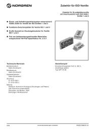
Single acting cylinders use compressed air for a power stroke<br />
in one direction only. The return stroke is effected by a<br />
mechanical spring located inside the cylinder. For single<br />
acting cylinders with no spring, some external force acting on<br />
the piston rod causes its return. Most applications require a<br />
single acting cylinder with the spring pushing the piston and<br />
rod to the instroked position. For other applications sprung<br />
outstroked versions can be selected. Figure 2 shows both<br />
types of single acting cylinder.<br />
Figure 2: Single acting cylinder<br />
The spring in a single acting cylinder is designed to provide<br />
sufficient force to return the piston and rod only. This allows<br />
for the optimum efficiency from the available air pressure.<br />
Most single acting cylinders are in the small bore and light duty<br />
model ranges and are available in a fixed range of stroke sizes.<br />
It is not practical to have long stroke or large bore single acting<br />
cylinders because of the size and cost of the springs needed.<br />
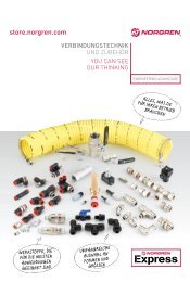
Single acting cylinders with no spring have the full thrust or<br />
pull available for performing work. These are often double<br />
acting cylinders fitted with a breather filter in the port open to<br />
atmosphere. The cylinder can be arranged to have a powered<br />
outstroke or a powered instroke (Figure 3).<br />
Figure 3. Single acting cylinder with no spring, push and pull