Actuator Guide - Norgren Pneumatics. Motion Control Equipment ...
Actuator Guide - Norgren Pneumatics. Motion Control Equipment ...
Actuator Guide - Norgren Pneumatics. Motion Control Equipment ...

Create successful ePaper yourself
Turn your PDF publications into a flip-book with our unique Google optimized e-Paper software.
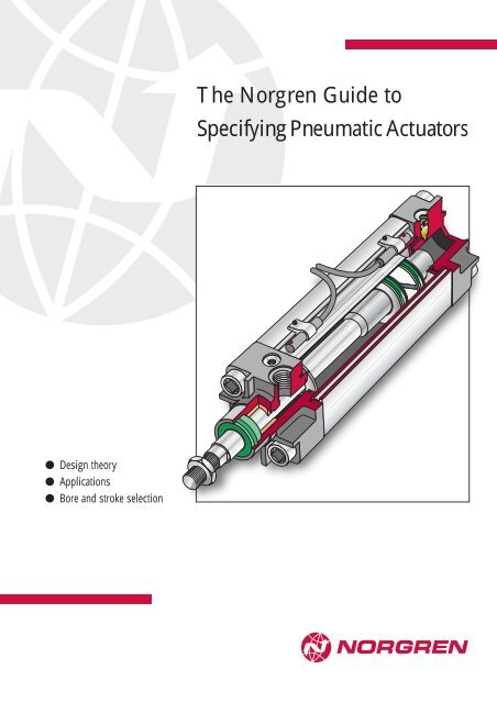
● Design theory<br />
● Applications<br />
● Bore and stroke selection<br />
The <strong>Norgren</strong> <strong>Guide</strong> to<br />
SpecifyingPneumatic <strong>Actuator</strong>s
CONTENTS<br />
Introduction 5<br />
Fundamental designs 5<br />
Single acting cylinders 5<br />
Double acting cylinders 6<br />
Magnetic cylinders 6<br />
Rodless cylinders 6<br />
Rotary actuators 6<br />
Clamping cylinders 7<br />
Bellows 7<br />
Cylinder sizing for thrust 8<br />
Useable thrust 8<br />
Clamping applications 9<br />
Dynamic applications 9<br />
Piston rod buckling 9<br />
Speed control 9<br />
Increasing speed 12<br />
Cycle times 12<br />
Cylinder air consumption 13<br />
Seals 14<br />
‘O’ ring piston seals 14<br />
Cup seals 15<br />
‘Z’ rings 15<br />
‘O’ ring barrel seals 15<br />
Cushion seals 15<br />
Piston rod seals 15<br />
Piston rod bellows 15<br />
Extreme operating temperatures 16<br />
Wear ring 16<br />
Cushion design 16<br />
Shock absorbers 17<br />
Standards 18<br />
Non standard dimensions 18<br />
Types of construction 19<br />
Sealed for life 19<br />
Micro cylinders 19<br />
Round line cylinders 19<br />
Small bore ISO 19<br />
Compact cylinders 12-40mm bore 19<br />
3<br />
Serviceable 20<br />
Light and medium duty 20<br />
Compact cylinders 50-100mm bore 20<br />
ISO/VDMA profile 20<br />
ISO/VDMA (exposed tie rod) 20<br />
Heavy Duty 20<br />
Mountings 21<br />
Rigid mountings 21<br />
Articulated mountings 21<br />
Installation 22<br />
Non rotational guiding 22<br />
Locking 23<br />
Rodless cylinders 24<br />
Rodless cylinder with brake 24<br />
Integrated valves 24<br />
Heavy duty rodless cylinder 25<br />
Cylinder variants 25<br />
Through rod 25<br />
Multi position 25<br />
Tandem 25<br />
Duplex 26<br />
Custom piston rod end 26<br />
Extreme operating temperatures 26<br />
Special Purpose <strong>Actuator</strong>s 26<br />
Double stroke cylinders 26<br />
Positioners and servo cylinders 27<br />
Open loop applications 27<br />
Closed loop applications 27<br />
In line positioners 28<br />
Servo cylinders 29<br />
Universal positioner 29<br />
Hollow piston rod cylinders 30<br />
Impact cylinders 31<br />
Principal of operation 31<br />
Installation 32<br />
Common terminology variants 32
LIST OF ILLUSTRATIONS<br />
Adjustable cushion cylinder 6<br />
Adjustable shock absorber 42<br />
Banjo flow regulators 25<br />
Bellows 14<br />
Braking unit 72<br />
Calculating equivalent mass 43<br />
Closed loop control 84<br />
Compact cylinder 47<br />
Compact guided cylinder 62<br />
Conventional flow regulators 24<br />
Cushion seal 36<br />
Cycle times 28<br />
Cylinder installation arrangements 20<br />
Detail of sealing strip section 68<br />
Double acting clamp cylinder 13<br />
Double acting non cushioned cylinder 4<br />
Double rack and pinion 11<br />
Double stroke (fixed carriage design) 81<br />
Duplex cylinder 79<br />
Effective length, centrally mounted cylinder 19<br />
Effective length, rear mounted cylinder 18<br />
Energy graph 94<br />
Energy ratings 92<br />
External cushioned circuit 40<br />
External guide 70<br />
Fixed cushion cylinder 5<br />
Fixed range positioner 85<br />
Four pillar frame 96<br />
Full and restricted port aperture 22<br />
Heavy duty cylinder 51<br />
Heavy duty rodless cylinder 75<br />
Hollow rod cylinder 91<br />
Impact cylinder and valve 93<br />
Integrated valve 73<br />
Internal guide 69<br />
ISO guide block 63<br />
ISO guide block with locking units 64<br />
ISO RM/8000 series 46<br />
Locking unit 66<br />
Long stroke 57<br />
M/29000 detail 87<br />
M/30000 detail 86<br />
Magnetic cylinder 7<br />
Main components of a cylinder 1<br />
Maximum stroke length 21<br />
Micro cylinder 44<br />
Mountings for ISO/VDMA cylinders 53<br />
Mountings for small bore ISO cylinders 52<br />
4<br />
Non adjustable unit 41<br />
Non-rotating VDMA 61<br />
‘O’ Ring section 32<br />
Offset load bending moment 59<br />
Open loop 83<br />
Out of alignment bearing 58<br />
Piston and rod diameters 15<br />
PRA/8000/M cylinder 49<br />
Pre-exhaust circuit 29<br />
Precision roller guide 71<br />
Proportional band graph 90<br />
Quick exhaust valve section 27<br />
RA/8000/M cylinder 50<br />
Rack and pinion 10<br />
Rigid mounting styles 54<br />
Rod bellows 38<br />
Rod/wiper seal 37<br />
Rodless cylinder 8<br />
Rodless cylinder mountings 74<br />
Rotary vane 9<br />
Round line cylinders 45<br />
Section of a ‘Z’ ring 34<br />
Section of a cup seal 33<br />
Section of barrel seal 35<br />
Section of Lintra 67<br />
Sequence of cushioning 39<br />
Serviceable compact 48<br />
Single acting clamp cylinder 12<br />
Single acting cylinder 2<br />
Single acting cylinder with no spring, push and pull 3<br />
Slide unit 65<br />
Speed graph 26<br />
Speed/pressure graph 23<br />
Swivel mounting styles 55<br />
Table of consumption 30<br />
Table of thrust and pulls, single acting cylinders 16<br />
Table of thrust and pulls, double acting cylinders 17<br />
Tandem cylinder 78<br />
Three stages of operation 95<br />
Three thread types 80<br />
Through rod 76<br />
Twin stroke principle 82<br />
Two cylinder multi position 77<br />
Types of seals 31<br />
Universal positioner 88<br />
Weight of cylinder 60<br />
Weight on the end of the rod 56<br />
Zero adjustment graph 89
INTRODUCTION<br />
Pneumatic actuators, of which cylinders are the most common,<br />
are the devices providing power and movement to automated<br />
systems, machines and processes. A pneumatic cylinder is a<br />
simple, low cost, easy to install device that is ideal for<br />
producing powerful linear movement over a wide range of<br />
velocities, and can be stalled without causing internal damage.<br />
Adverse conditions can be easily tolerated such as high<br />
humidity, dry and dusty environments and repetitive<br />
cleandown with high pressure hoses.<br />
The diameter or bore of a cylinder determines the maximum<br />
force that it can exert and the stroke determines the maximum<br />
linear movement that it can produce. Cylinders are designed to<br />
work at different maximum pressures up to 16 bar. The<br />
pressure actually supplied to a cylinder will normally be<br />
reduced through a pressure regulator to control the thrust to a<br />
suitable level. As an example of cylinder power, a 40mm bore<br />
cylinder working at 6 bar could easily lift an 80kg man.<br />
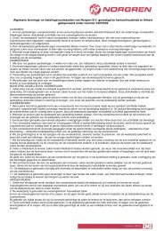
The basic construction of a typical double acting single rod<br />
cylinder is shown in the cut away section (Figure 1), where the<br />
component parts can be identified.<br />
13<br />
14<br />
12<br />
11<br />
Figure 1: Main components of a cylinder<br />
10<br />
1<br />
9<br />
Key:<br />
1 Cushion seal 8 Front port<br />
2 Magnet 9 Magnetically operated switch<br />
3 Cushion sleeve 10 Piston rod<br />
4 Barrel 11 Wear ring<br />
5 Nose bearing 12 Piston seal<br />
6 Rod seal and wiper 13 Rear end cover<br />
7 Front end cover 14 Cushion adjustment screw<br />
2<br />
8<br />
Pneumatic actuators are made in a wide variety of sizes, styles<br />
and types including those giving a semi rotary output. Each<br />
major type will be covered in concept.<br />
3<br />
7<br />
4<br />
5<br />
6<br />
5<br />
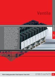
FUNDAMENTAL DESIGNS<br />
SINGLE ACTING CYLINDERS<br />
Single acting cylinders use compressed air for a power stroke<br />
in one direction only. The return stroke is effected by a<br />
mechanical spring located inside the cylinder. For single<br />
acting cylinders with no spring, some external force acting on<br />
the piston rod causes its return. Most applications require a<br />
single acting cylinder with the spring pushing the piston and<br />
rod to the instroked position. For other applications sprung<br />
outstroked versions can be selected. Figure 2 shows both<br />
types of single acting cylinder.<br />
Figure 2: Single acting cylinder<br />
The spring in a single acting cylinder is designed to provide<br />
sufficient force to return the piston and rod only. This allows<br />
for the optimum efficiency from the available air pressure.<br />
Most single acting cylinders are in the small bore and light duty<br />
model ranges and are available in a fixed range of stroke sizes.<br />
It is not practical to have long stroke or large bore single acting<br />
cylinders because of the size and cost of the springs needed.<br />
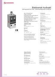
Single acting cylinders with no spring have the full thrust or<br />
pull available for performing work. These are often double<br />
acting cylinders fitted with a breather filter in the port open to<br />
atmosphere. The cylinder can be arranged to have a powered<br />
outstroke or a powered instroke (Figure 3).<br />
Figure 3. Single acting cylinder with no spring, push and pull
DOUBLE ACTING CYLINDERS<br />
Double acting cylinders use compressed air to power both the<br />
outstroke and instroke. This makes them ideal for pushing and<br />
pulling within the same application. Superior speed control is<br />
possible with a double acting cylinder, achieved by controlling<br />
the exhausting back pressure.<br />
Non cushioned cylinders will make metal to metal contact<br />
between the piston and end covers at the extreme ends of<br />
stroke. They are suitable for full stroke working only at slow<br />
speeds which result in gentle contact at the ends of stroke<br />
(Figure 4). For faster speed, external stops with shock<br />
absorption are required. These should be positioned to prevent<br />
internal contact between the piston and end covers.<br />
Figure 4: Double acting non cushioned cylinder<br />
Cushioned cylinders have a built in method of shock<br />
absorption. Small bore light duty cylinders have fixed cushions<br />
which are simply shock absorbing discs fixed to the piston or<br />
end cover (Figure 5).<br />
Figure 5: Fixed cushion cylinder<br />
Other cylinders have adjustable cushioning. This progressively<br />
slows the piston rod down over the last part of the stroke by<br />
controlling the escape of a trapped cushion of air (Figure 6).<br />
The cushion action is covered in detail later (Figure 38).<br />
Figure 6: Adjustable cushion cylinder<br />
MAGNETIC CYLINDERS<br />
Magnetic cylinders have a band of magnetic material around<br />
the circumference of the piston and are fitted with a nonmagnetic<br />
cylinder barrel. The magnetic field can be imagined<br />
as the shape of a donut around the barrel. This will travel with<br />
the piston as the piston rod moves in and out. By placing<br />
6<br />
magnetically operated switches on the outside of the barrel,<br />
one at each end for example, signals will be received each<br />
time the piston rod completes a stroke (Figure 7).<br />
Figure 7: Magnetic cylinder<br />
RODLESS CYLINDERS<br />
For some applications it is desirable to contain the movement<br />
produced by a cylinder within the same overall length taken up<br />
by the cylinder body. For example, action across a conveyor<br />
belt, or for vertical lifting in spaces with confined headroom.<br />
The novel design of a rodless cylinder is ideal in these<br />
circumstances. The object to be moved is attached to a<br />
carriage running on the side of the cylinder barrel. A slot, the<br />
full length of the barrel, allows the carriage to be connected to<br />
the piston. Long sealing strips on the inside and outside of the<br />
cylinder tube prevent loss of air and ingress of dust. The slot is<br />
unsealed only between the lip seals on the piston as it moves<br />
backwards and forwards (Figure 8). Direction and speed<br />
control is by the same techniques as applied to conventional<br />
cylinders.<br />
Figure 8: Rodless cylinder<br />
ROTARY ACTUATORS<br />
S<br />
There are many applications that require a turning or twisting<br />
movement such as turning components over in a drilling jig or<br />
providing a wrist action on a pick and place device. Rotary<br />
actuators provide angular rotation up to 360°. A typical rotary<br />
vane design is shown in (Figure 9).<br />
Figure 9: Rotary vane
Another form of rotary actuator is the rack and pinion design.<br />
The basic double acting rack and pinion design is shown in<br />
(Figure 10). These larger actuators are often used in the<br />
process industry to operate quarter turn valves.<br />
Figure 10: Rack and pinion<br />
The torque output can be doubled by adding a second actuator<br />
to drive the same pinion (Figure 11).<br />
Figure 11: Double rack and pinion<br />
CLAMPING CYLINDERS<br />
For use in confined spaces where only a short stroke is<br />
required these cylinders have a small axial overall dimension<br />
for their bore size. They are mostly used in single acting<br />
versions (Figure 12), but are also available as double acting<br />
through-rod styles (Figure 13). They are usually used in light<br />
duty applications.<br />
Figure 12: Figure 13:<br />
Single acting clamp cylinder Double acting clamp cylinder<br />
7<br />
BELLOWS<br />
Bellows are durable single acting concertina like actuators<br />
which extend when inflated and are similar to the air<br />
suspension units seen on<br />
large trucks. They provide<br />
powerful short strokes and<br />
have all round compliance<br />
allowing them to bend in<br />
any direction (Figure 14).<br />
Single, double and triple<br />
convolution types provide a<br />
range of strokes with power Figure 14: Bellows<br />
developed from nominal<br />
diameters in the range 70mm to 546mm. Loads varying in<br />
angle up to a maximum of 30° from the actuator axis can be<br />
accommodated.<br />
These actuators can be used as air springs and are ideal for<br />
isolating the vibration of supported loads from the actuators<br />
base mounting. To avoid the accumulation of moisture if used<br />
with wet air, bellows should be installed with the port facing<br />
down, to assist expulsion with the exhaust on each cycle.<br />
Caution: The maximum extension and compression of the<br />
bellows must be limited by external restraints. The bellows<br />
must never be pressurised while unrestrained as it will over<br />
extend and the end plate is likely to be blown free and could<br />
cause serious injuries. When the bellows are exhausted the<br />
load must be prevented from crushing it by means of external<br />
stops.
CYLINDER SIZING FOR THRUST<br />
The theoretical thrust (outstroke) or pull (instroke) of a cylinder<br />
is calculated by multiplying the effective area of the piston by the<br />
working pressure. The effective area for thrust is the full area of<br />
the cylinder bore. The effective area for pull is reduced by the<br />
cross section area of the piston rod (Figure 15).<br />
Figure 15: Piston and rod diameters<br />
Current practice specifies bore (D) and piston rod diameter (d)<br />
in millimetres and working pressure (P) in bar gauge. In the<br />
formula, P is divided by 10 to express pressure in Newtons per<br />
square millimetre (1 bar = 0.1 N/mm 2 )<br />
The theoretical force (F) is given by<br />
Thrust F =<br />
Pull F =<br />
Where<br />
D = Cylinder bore in millimetres<br />
d = Piston rod diameter in millimetres<br />
P = Pressure in bar<br />
F = Thrust or Pull in Newtons<br />
Example:<br />
Find the theoretical thrust and pull of a 50mm bore cylinder<br />
supplied with a pressure of 8 bar<br />
Thrust F =<br />
Pull F =<br />
d<br />
D<br />
πD<br />
40<br />
2P Newtons<br />
π(D<br />
40<br />
2-d 2 )P<br />
Newtons<br />
π 50<br />
40<br />
2 . 8<br />
= 1571 Newtons<br />
π(50<br />
40<br />
2-20 2 ).8<br />
= 1319 Newtons<br />
Calculating the thrust or pull of single acting cylinders with a<br />
spring is more complicated. The spring force opposing the thrust<br />
or pull will progressively increase as more of the stroke is<br />
achieved. This must be subtracted to find the theoretical force.<br />
In practice thrust and pull values for double acting and single<br />
acting cylinders can be obtained from the catalogue covering<br />
the selected cylinder range. These will be given for a<br />
particular pressure, usually 6 bar. The values for other<br />
pressures can be easily calculated by multiplying by the new<br />
pressure divided by 6.<br />
When estimating the relative thrusts of cylinders with different<br />
bore sizes, it can be useful to remember that thrust increases<br />
with the square of the diameter. In other words if you double the<br />
bore you will quadruple the thrust (Figures 16&17).<br />
8<br />
Cylinder bore<br />
mm<br />
Figure 16: Table of thrust and pulls, single acting cylinders<br />
Cylinder bore<br />
mm (inches)<br />
Thrust N<br />
at 6 bar<br />
Figure 17: Table of thrust and pulls, double acting cylinders<br />
USABLE THRUST<br />
Piston rod<br />
diameter<br />
mm (inches)<br />
Min pull of<br />
spring N<br />
10 37 3<br />
12 59 4<br />
16 105 7<br />
20 165 14<br />
25 258 23<br />
32 438 27<br />
40 699 39<br />
50 1102 48<br />
63 1760 67<br />
80 2892 86<br />
100 4583 99<br />
Thrust N<br />
at 6 bar<br />
Pull N<br />
at 6 bar<br />
8 3 30 25<br />
10 4 47 39<br />
12 6 67 50<br />
16 6 120 103<br />
20 8 188 158<br />
25 10 294 246<br />
32 12 482 414<br />
40 16 753 633<br />
44.45 (1.75) 16 931 810<br />
50 20 1178 989<br />
63 20 1870 1681<br />
76.2 (3) 25 2736 2441<br />
80 25 3015 2721<br />
100 25 4712 4418<br />
125 32 7363 6881<br />
152.4 (6) (1 1 /2) 10944 10260<br />
160 40 12063 11309<br />
200 40 18849 18095<br />
250 50 29452 28274<br />
304.8 (12) (2 1 /4) 43779 42240<br />
320 63 48254 46384<br />
355.6 (14) (2 1 /4) 59588 58049<br />
When selecting a cylinder size and suitable operating pressure,<br />
an estimation must be made of the actual thrust required. This<br />
is then taken as a percentage of the theoretical thrust of a<br />
suitably sized cylinder. The percentage chosen will depend on<br />
whether the thrust is required at the end of movement as in a<br />
clamping application or during movement such as when lifting<br />
a load.
CLAMPING APPLICATIONS<br />
In a clamping application the force is developed as the cylinder<br />
stops. This is when the pressure differential across the piston<br />
reaches a maximum. The only losses from the theoretical<br />
thrust will be those caused by friction. These can be assumed<br />
to be acting even after the piston has stopped. As a general<br />
rule, make an allowance of 10% for friction. This may be more<br />
for very small bore cylinders and less for very large ones.<br />
If the cylinder is operating vertically up or down the mass of<br />
any clamping plates will diminish or augment the clamping<br />
force.<br />
DYNAMIC APPLICATIONS<br />
The actual thrust and speed from a moving cylinder are<br />
determined by friction and the rate at which air can flow in and<br />
out of the cylinder’s ports. The thrust or pull developed is<br />
divided into two components. One for moving the load, the<br />
other for creating a back pressure to help expel the air on the<br />
exhausting side of the piston.<br />
For a lightly loaded cylinder, most of the thrust is used to expel<br />
the back pressure and will result in a moderately fast speed.<br />
This is self limiting however as the faster the speed, the less<br />
will be the pressure differential across the piston. This is due<br />
to the increasing resistance through the ports, tubing, fittings<br />
and valve as the rate of flow increases.<br />
For a heavily loaded cylinder most of the thrust is used to move<br />
the load. The exhausting pressure will fall considerably to give a<br />
higher pressure differential before movement starts. The<br />
acceleration and speed will be determined by the inertia of the<br />
load and rate at which the lower back pressure is expelled. A<br />
heavy load simply diverts a greater proportion of the power of<br />
the cylinder away from creating a back pressure to moving the<br />
load. Although the speed for a heavily loaded cylinder is going to<br />
be slower it is not unreasonably so, providing the cylinder has<br />
been correctly chosen. As a general rule, the estimated thrust<br />
requirement should be between 50% and 75% of the theoretical<br />
thrust. This should give sufficient back pressure for a wide range<br />
of adjustable speed control when fitting flow regulators.<br />
9<br />
PISTON ROD BUCKLING<br />
Some applications require very long stroke cylinders. If there is<br />
a compressive axial load applied to the piston rod, care must<br />
be taken to ensure that the system parameters of length,<br />
diameter and load are within the safety limits to prevent<br />
buckling.<br />
There was a long standing belief that cylinder stroke lengths<br />
were limited to a maximum of 15 times the diameter of the<br />
bore. Whilst this gave a general indication of maximum stroke<br />
length, it did not take into account mounting support factors.<br />
In many instances the nature of the application and the style of<br />
mounting to be used allow greater stroke lengths, whilst in<br />
others the stroke length is considerably less.<br />
To calculate maximum stroke length the following formula<br />
should be used:<br />
F k =<br />
L 2 π<br />
. S<br />
2 . E . J<br />
Where<br />
Fk = Permissible buckling force in Newtons<br />
E = Modulus of Elasticity<br />
J = Moment of Inertia<br />
L = Effective length in millimetres<br />
S = Safety factor, normally 5<br />
One of the elements in this formula, Effective length, needs<br />
some explanation.<br />
Effective length x support factor = MAX STROKE LENGTH<br />
Figure 18 shows an extended cylinder, with a clevis mounted at<br />
the piston rod end and a trunnion mounted at the rear end. The<br />
load being moved is rigidly guided. The distance L is the total<br />
length that has the buckling force applied to it. This cylinder<br />
mounting arrangement has a support factor of 0.6.<br />
Figure 18: Effective length, rear mounted cylinder<br />
Figure 19 shows a different mounting. The piston rod is<br />
directly mounted to the load and the cylinder is central trunnion<br />
mounted. The load applied is rigidly guided. This configuration<br />
has a support factor of 1.3.<br />
l<br />
l<br />
Figure 19: Effective length, centrally mounted cylinder
The effective length and the support factor have a direct effect<br />
upon the maximum permissible stroke length. A full table of<br />
support factors is shown in Figure 20.<br />
Figure 20: Cylinder installation arrangements<br />
Support factor<br />
0.5<br />
1.2<br />
1.2<br />
0.5<br />
1.2<br />
1.2<br />
0.5<br />
2.0<br />
1.4<br />
0.8<br />
0.7<br />
0.6<br />
0.7<br />
1.1<br />
1.3<br />
The following graph (Figure 21) is based on the formula<br />
mentioned above. It allows calculation of the effective length<br />
(and thus maximum stroke length), piston rod diameter or<br />
permissible buckling force when two of the three factors are<br />
known.<br />
The table of support factors MUST be used in conjunction with<br />
the graph.<br />
Example:<br />
The requirement is for a cylinder, piston rod diameter 16mm,<br />
stroke length 1100mm. The force exerted on the piston rod is<br />
10<br />
100000<br />
Effective Length* mm<br />
10000<br />
1000<br />
100<br />
9<br />
8<br />
7<br />
6<br />
5<br />
4<br />
3<br />
2<br />
9<br />
8<br />
7<br />
6<br />
5<br />
4<br />
3<br />
2<br />
9<br />
8<br />
7<br />
6<br />
5<br />
4<br />
3<br />
2<br />
9<br />
8<br />
7<br />
6<br />
5<br />
4<br />
3<br />
2<br />
10 2 3 4 5 6 7 89 2 3 4 5 6 7 89 2 3 4 5 6 7 89 2 3 4 5 6 7 89<br />
10 100 1000 10000 100000<br />
Figure 21: Maximum stroke length<br />
3000N and the mounting style gives a support factor of 2.0.<br />
From the horizontal axis F = 3000N read vertically up to the<br />
intersection point with the 16mm piston rod diameter line.<br />
From the point of intersection read horizontally to the left to<br />
establish the effective length L. Multiply this effective length by<br />
the support factor 2.0 to give the Maximum Stroke Length for<br />
the cylinder.<br />
650 x 2.0 = 1300mm Maximum stroke length.<br />
Therefore a cylinder stroke length of 1100mm is acceptable in<br />
this application.<br />
A further requirement is for a stroke length of 1200mm on a<br />
cylinder with a piston rod diameter of 12mm. The force exerted<br />
on the piston rod is 290N and the cylinder mounting style has<br />
a support factor of 0.6.<br />
Using the same method as described previously we find that<br />
the effective length L = 1180.<br />
1180 x 0.6 = 708 Maximum stroke length.<br />
Therefore this cylinder is unsuitable for this application.<br />
There are two solutions:<br />
1. Improve the support factor by changing the mounting<br />
arrangement, or<br />
2. Use a larger bore cylinder which has a piston rod diameter<br />
of 16mm or above.<br />
In order to avoid undue vibration and shock loading during<br />
cushioning, it is recommended that operating speed is<br />
regulated and cushion action is as smooth as possible. It<br />
should be accepted that cylinder stroke lengths are, in practice,<br />
limited by the maximum single length of barrel which is<br />
available in raw material form.<br />
4<br />
Applied Force N<br />
6<br />
63<br />
50<br />
40<br />
32<br />
25<br />
20<br />
16 22<br />
12 18<br />
10<br />
8 Piston Rod Diameter<br />
* Effective length given here must be multiplied by support factor to give Actual Stroke Length
SPEED CONTROL<br />
For many applications, cylinders can be allowed to run at their<br />
own maximum natural speed. This results in rapid mechanism<br />
movement and quick overall machine cycle times. However,<br />
there will be applications where uncontrolled cylinder speed<br />
can give rise to shock fatigue, noise and extra wear and tear to<br />
the machine components. The factors governing natural piston<br />
speed and the techniques for controlling it are covered in this<br />
section.<br />
The maximum natural speed of a cylinder is determined by:<br />
• cylinder size<br />
• port size<br />
• inlet and exhaust valve flow<br />
• air pressure<br />
• bore and length of the hoses<br />
• load against which the cylinder is working.<br />
From this natural speed it is possible to either increase speed<br />
or as is more often the requirement, reduce it.<br />
First we will look at how the natural speed for any given load<br />
can be changed by valve selection. Generally, the smaller the<br />
selected valve the slower the cylinder movement. When<br />
selecting for a higher speed however, the limiting factor will be<br />
the aperture in the cylinder ports (Figure 22). Valves with flow<br />
in excess of this limitation will give little or no improvement in<br />
cylinder speed. The aperture in the cylinder ports is determined<br />
by the design. Robustly constructed cylinders will often be<br />
designed with full bore ports. This means that the most<br />
restrictive part of the flow path will be the pipe fitting. These<br />
cylinders are the type to specify for fast speed applications and<br />
would be used with a valve having at least the same size ports<br />
as the cylinder. Lighter duty designs, particularly small bore<br />
sizes, will have the port aperture much smaller than the port’s<br />
nominal thread size. This has the desired effect of limiting the<br />
speed of the cylinder to prevent it from self destructing through<br />
repeated high velocity stroking. The maximum natural speed of<br />
these cylinders can often be achieved with a valve that is one<br />
or two sizes down from the cylinder port size.<br />
Figure 22: Full and restricted port aperture<br />
Larger bore cylinders are designed with port sizes large<br />
enough to allow fast maximum speeds. In many applications<br />
however they are required to operate at relatively low speeds.<br />
For an application like this, a cylinder can be driven from a<br />
valve with smaller sized ports than those of the cylinder.<br />
Once a cylinder/valve combination has been chosen, and the<br />
load is known, the natural maximum speed will be dependent<br />
on pressure. For an installed cylinder and load, an experiment<br />
can be carried out. Connect a control valve that will cause the<br />
cylinder to self reciprocate. Then start the system running at a<br />
low pressure and gradually increase it. The cylinder will cycle<br />
faster and faster until a limiting speed is reached. This is the<br />
11<br />
optimum pressure for that application. Increase the pressure<br />
further and the cylinder starts to slow down. This is caused by<br />
too much air entering the cylinder on each stroke. More time is<br />
therefore taken to exhaust it and results in a slower cylinder<br />
speed.<br />
With any fixed combination of valve, cylinder, pressure and<br />
load, it is usually necessary to have adjustable control over the<br />
cylinder speed. This is effected with flow regulators, and allows<br />
speed to be tuned to the application.<br />
For the majority of applications, best controllability results<br />
from uni-directional flow regulators fitted to restrict the flow<br />
out of the cylinder and allow free flow in. The regulator fitted to<br />
the front port controls the outstroke speed and the one fitted to<br />
the rear port controls the instroke speed. Speed is regulated by<br />
controlling the flow of air to exhaust which maintains a higher<br />
back pressure. The higher the back pressure the more constant<br />
the velocity against variations in load, friction and driving force.<br />
On the other side of the piston full power driving pressure is<br />
quickly reached. Many flow regulators are designed specifically<br />
for this convention.<br />
The graph below (Figure 23), shows the behaviour of pressure<br />
and speed during the stroke of a typical cylinder fitted with flow<br />
regulators.<br />
bar<br />
10<br />
8<br />
6<br />
4<br />
2<br />
0<br />
0<br />
a<br />
Differential to maintain velocity<br />
against load and friction<br />
movement starts<br />
valve switched<br />
P1: pressure driving<br />
the piston forward<br />
P2: back pressure on the<br />
annular side of the piston<br />
P1<br />
P2<br />
Figure 23: Speed/pressure graph<br />
Velocity<br />
Time<br />
movement ends<br />
V m/s<br />
If speed is controlled by fitting uni-directional flow regulators<br />
the other way round, velocity will not be as constant or as<br />
controllable. The back pressure will quickly exhaust and the<br />
restricted flow on the other side of the piston will slowly build<br />
to just enough pressure differential to cause movement.<br />
Precise speeds are difficult to adjust as the variables in load<br />
and friction represent a higher percentage of the total load.<br />
Also, for fast speeds on adjustable cushion types the<br />
cushioning will be less effective. For very slow speeds and light<br />
loads the movement can be jerky. It is caused by the difference<br />
between static and dynamic friction. Pressure builds up to<br />
break the piston out of static friction then the lower dynamic<br />
friction allows it to accelerate. The restricted flow cannot keep<br />
up with it so the pressure drops and the piston stops. The<br />
sequence is then repeated.<br />
1,0<br />
0,8<br />
0,6<br />
0,4<br />
0,2<br />
0<br />
Load
There are however applications that require the unconventional<br />
restriction of flow into a cylinder for speed control and will be<br />
acceptable for moderate and fast speed settings. One example<br />
is the power stroke of a single acting cylinder where there is no<br />
back pressure side to control. Another example is a special<br />
case for a double acting cylinder, which has the back pressure<br />
side pre-exhausted. A flow regulator controlling the back<br />
pressure will have little effect as the back pressure starts at<br />
atmosphere and has to be built by the stroke of the cylinder. A<br />
further example is the control of some small bore double acting<br />
cylinders. With conventional flow control the piston rod gives<br />
a characteristic leap forward at the beginning of the outstroke.<br />
This is due to the relatively large diameter of the rod to bore<br />
ratio and therefore large differential area across the piston. The<br />
leap forward intensifies the exhausting pressure to balance the<br />
forces before speed control is effective. This problem is solved<br />
by regulating the flow in to the cylinder.<br />
The most versatile type of adjustable flow regulator is the unidirectional,<br />
line mounted model (Figure 24).<br />
z,yz<br />
Figure 24: Conventional flow regulators<br />
The line mounted flow regulator can be fitted at any position in<br />
the line between the valve and cylinder ports determined by the<br />
application. It can be fitted either way round to suit<br />
conventional exhaust or special inlet regulation requirements.<br />
It consists of a screw with a<br />
tapered needle end. As the<br />
taper is screwed further into<br />
the orifice, so flow is<br />
increasingly restricted. When<br />
flow is reversed, the orifice<br />
disc which also forms a non<br />
return valve, lifts to allow<br />
unrestricted flow.<br />
A popular alternative design is<br />
the elbow banjo flow regulator<br />
(Figure 25). This regulator is<br />
designed to fit directly in to the<br />
cylinder port, so placing<br />
adjustment at the appropriate<br />
cylinder end. It gives conventional<br />
Figure 25: Banjo flow regs<br />
flow restriction out of the cylinder and free flow in.<br />
As an approximate guide, the graph (Figure 26), shows the<br />
likely maximum speeds that can be achieved with typical<br />
combinations of valve Cv and cylinder bore against percentage<br />
loading.<br />
zz{ ||,y z | {<br />
,yz,y zz || {<br />
,yz{|,y<br />
{<br />
{| ,y<br />
12<br />
Speed mm / s<br />
2,000<br />
1,800<br />
1,600<br />
1,400<br />
1,200<br />
1,000<br />
800<br />
600<br />
400<br />
200<br />
0<br />
100 80 50<br />
Load %<br />
30 10<br />
Figure 26: Speed graph<br />
INCREASING SPEED<br />
In some applications cylinder speed can be improved by using<br />
a quick exhaust valve.<br />
This allows air to flow from the control valve in to the cylinder<br />
past a poppet lip seal (Figure 27). When the control valve is<br />
operated to reverse the cylinder, the lower pressure on the<br />
valve side of the poppet seal allows it to rapidly open<br />
exhausting the air in the cylinder through the large exhaust port<br />
and silencer. Because this bypasses the tubing and main<br />
control valve, the flow is faster and the back pressure is less.<br />
This allows the cylinder to accelerate more rapidly. Increases of<br />
up to 50% of the cylinder’s natural speed can be achieved<br />
depending on the cylinder type and loading. A quick exhaust<br />
valve must be fitted directly to the cylinder port. If high speed<br />
is required in both directions, both of the cylinder’s ports must<br />
be fitted with quick exhaust valves.<br />
Figure 27: Quick exhaust valve section<br />
Warning: A cylinder’s in built cushioning will be less effective<br />
when used in conjunction with a quick exhaust valve. This is<br />
due to the increased speed and lower back pressure. External<br />
cushioning is likely to be required.<br />
CYCLE TIMES<br />
z,yz , y,yz<br />
z , y<br />
{|,yz, z|<br />
y{|,yz, z|<br />
y{ ,y,y z ,yz<br />
2<br />
2<br />
{<br />
2<br />
1<br />
1<br />
1<br />
Lintra<br />
Piston rod<br />
Cylinders<br />
Cv 0.4 & 25 dia<br />
Cv 1.0 & 32 dia<br />
Cv 4.0 & 80 dia<br />
Cv 0.4 & 50 dia<br />
Cv 0.35 & 25 dia<br />
Cv 6.0 & 250 dia<br />
For estimating the likely cycle time of a cylinder in an<br />
application, it is necessary to take into account the response<br />
time of the valve and cylinder in combination.<br />
The table of cycle times (Figure 28), are for double acting<br />
cylinders with a 150mm stroke. They perform one cycle
(outstroke and instroke)<br />
controlled by 5/2<br />
solenoid/spring valves.<br />
Bore Valve<br />
ports<br />
Cv Time<br />
m secs<br />
Connection is with a 6- 20 1/8 0.3 225<br />
bar pressure supply and 50 1/8 0.4 700<br />
1m of tubing between<br />
valve and cylinder. The<br />
63 1/4 1.0 525<br />
piston rod is not loaded. 100 1/4 1.0 1100<br />
Another way of 160 1/2 3.5 950<br />
increasing the speed of<br />
a cylinder is to preexhaust<br />
it. This involves<br />
200<br />
200<br />
1/2<br />
1<br />
3.5<br />
7.8<br />
1560<br />
650<br />
using a separate valve<br />
for each end of the<br />
320 1 7.8 1280<br />
cylinder (Figure 29). The Figure 28: Cycle times<br />
pressurised end of the<br />
cylinder is first exhausted so there is no back pressure. Then<br />
the valve on the other end is operated to drive the piston.<br />
2<br />
2<br />
12 10<br />
10 12<br />
3<br />
Figure 29: Pre-exhaust circuit<br />
This technique can result in some very fast speeds due to the<br />
higher pressure differential across the piston. It is the basis of<br />
a control used in high speed rodless cylinder applications<br />
producing up to 20 metres/second and is also the basis of the<br />
special Impact cylinder.<br />
Warning: A cylinder’s in built cushioning will be less effective<br />
when the cylinder is used pre exhausted. External cushioning<br />
is likely to be required.<br />
CYLINDER AIR CONSUMPTION<br />
The need to calculate the consumption of a cylinder is most<br />
often for estimating the total consumption of an application.<br />
There are two parts to the air consumption of a cylinder. One is<br />
the volume displaced by the piston multiplied by the absolute<br />
working pressure. The other is the unswept volume such as<br />
cavities in the end cover and piston, the cylinder ports, tubing<br />
and valve cavities, all multiplied by the gauge pressure. The<br />
unswept part is likely to be a small percentage and will vary<br />
with individual installations. A general allowance of around 5%<br />
can be added to cover this.<br />
For a double acting cylinder the volume of free air displaced by<br />
the piston in one complete cycle will be:<br />
Push stroke πD<br />
V =<br />
4<br />
2 . S . (Ps+Pa) . 10 -6<br />
1<br />
1 3<br />
13<br />
Pull stroke<br />
V =<br />
π (D<br />
4<br />
2 - d 2 ) . S . (Ps+Pa) . 10 -6<br />
Where V = volume in dm 3 free air<br />
D = cylinder bore mm<br />
d = rod diameter mm<br />
S = stroke mm<br />
Ps = supply gauge pressure (bar gauge)<br />
Pa = atmospheric pressure (assumed to be 1 bar<br />
absolute)<br />
If a cylinder is part of an automatic system, its average<br />
consumption rate in dm 3 /s free air per cycle of the system can<br />
be found. Multiply the consumption of one cycle by the number<br />
of cycles of the cylinder per cycle of the system, then divide by<br />
the system cycle time in seconds.<br />
To estimate the total average air consumption of a pneumatic<br />
system carry out the above procedure for each cylinder in the<br />
system. Add these values together and add 5%.<br />
It is important to understand that the instantaneous flow<br />
requirement for a system will be higher than the average and in<br />
some cases very much higher.<br />
For example, a machine has a 2 minute cycle time and is<br />
working at a line pressure of 8 bar. It has a large cylinder<br />
(200mm bore and 1000mm stroke) which outstrokes and<br />
instrokes once, consuming 554 dm 3 free air in each machine<br />
cycle.<br />
Over the 2 minute machine cycle time this is an average<br />
consumption of 4.6 dm 3 /s free air. Consider two cases for this<br />
machine.<br />
In case (1) it takes 30 seconds for the cylinder to complete one<br />
cycle and is dormant for 90 seconds. The average flow it<br />
requires per cycle of the machine is still 4.6 dm 3 /s free air.<br />
In case (2) it completes one cycle in only 6 seconds and is<br />
dormant for 114 seconds. The average consumption is the<br />
same again, 4.6 dm 3 /s free air.<br />
In each case it has performed just one cycle in 2 minutes.<br />
However if we look at the average dynamic demand (the flow<br />
requirement while the cylinder is moving), then in the first case<br />
this is 18.5 dm 3 /s free air and in the second case is 92.4 dm 3 /s<br />
free air. This shows that the air supply capacity to the machine<br />
for case (2) must be substantially larger than that which is<br />
suitable for case (1) although both consume the same amount<br />
of air per machine cycle or per hour.<br />
For a whole machine it is important to ensure that the worst<br />
case demand can be satisfied, otherwise there will be air<br />
starvation at that time and performance may suffer. To estimate<br />
the flow requirement to a machine, first find the average<br />
dynamic demand for each cylinder and any other devices<br />
consuming air. Plot them on a time based machine function<br />
diagram. The worst case point, where overlapping functions<br />
are taking place, must be found and the individual demand<br />
rates added together. The result will be the minimum capacity<br />
the air supply needs to be for the application. If this value is<br />
very high and of a relatively short duration, it could be satisfied<br />
by a supply with enough capacity for the average machine<br />
cycle demand flowing in to a local air receiver. This will take in<br />
a charge during instances of low demand and give it out during<br />
instances of high demand.
Clearly during the operation of individual cylinders there will be<br />
instantaneous peaks above the dynamic average values. These<br />
can be complicated to calculate as they are dependent on the<br />
load characteristics of each cylinder. In any case they will not<br />
last for very long and can usually be ignored.<br />
In general it is good practice to connect pneumatic applications<br />
to a supply line with capacity well in excess of their calculated<br />
requirement. This will ensure good performance is maintained<br />
in the event of future extensions to the machine and the<br />
addition of other machines or equipment to the same air line.<br />
The table of consumption of free air dm 3/mm of stroke/cycle<br />
(Figure 30), will serve as a ready source of data for a typical<br />
range of cylinders. Take each figure and multiply by the stroke<br />
in mm. For pressures other than 6 bar multiply by the absolute<br />
pressure divided by seven.<br />
Bore<br />
mm<br />
Rod<br />
mm<br />
Push stroke<br />
consumption<br />
dm 3 /mm of<br />
stroke at 6 bar<br />
Figure 30: Table of consumption<br />
Pull stroke<br />
consumption<br />
dm 3 /mm of<br />
stroke at 6 bar<br />
Combined<br />
consumption<br />
dm 3 /mm of<br />
stroke/cycle<br />
10 4 0.00054 0.00046 0.00100<br />
12 6 0.00079 0.00065 0.00144<br />
16 6 0.00141 0.00121 0.00262<br />
20 8 0.00220 0.00185 0.00405<br />
25 10 0.00344 0.00289 0.00633<br />
32 12 0.00563 0.00484 0.01047<br />
40 16 0.00880 0.00739 0.01619<br />
50 20 0.01374 0.01155 0.02529<br />
63 20 0.02182 0.01962 0.04144<br />
80 25 0.03519 0.03175 0.06694<br />
100 25 0.05498 0.05154 0.10652<br />
125 32 0.08590 0.08027 0.16617<br />
160 40 0.14074 0.13195 0.27269<br />
200 40 0.21991 0.21112 0.43103<br />
250 50 0.34361 0.32987 0.67348<br />
SEALS<br />
There are a variety of seals required within a pneumatic<br />
cylinder. Single acting non cushioned cylinders use the least,<br />
double acting adjustable cushioned cylinders use the most<br />
(Figure 31).<br />
z {<br />
|<br />
14<br />
{ Figure 31: Types of seals<br />
,y<br />
1 2 3 4<br />
,y<br />
5 6<br />
zz<br />
{ | {|{<br />
Key:<br />
1) Cushion screw seal 4) Piston seal<br />
2) Cushion seal 5) Barrel seal<br />
3) Wear ring 6) Piston rod/wiper seal<br />
A sliding seal such as fitted to a piston, has to push outwards<br />
against the sliding surface with enough force to prevent<br />
compressed air from escaping, but keep that force as low as<br />
possible to minimise the frictional resistance. This is a difficult<br />
trick to perform, since the seal is expected to be pressure tight<br />
from zero pressure to 10 bar or more.<br />
There is a large difference between static and dynamic friction.<br />
Static friction or break-out friction as it is sometimes called<br />
builds up when the piston stops moving. Seals inherently need<br />
to exert a force radially outward to maintain a seal. This force<br />
gradually squeezes out any lubricants between the seal and the<br />
barrel wall and allows the seal to settle in to the fine surface<br />
texture. After the piston has been standing for a while, the<br />
pressure required to start movement is therefore higher than it<br />
would be if it is moved again immediately after stopping. To<br />
minimise this effect, seals should have a low radial force and<br />
high compliance. High compliance allows the seal to<br />
accommodate differences in tolerance of the seal moulding and<br />
machined parts without affecting the radial force by a great<br />
degree.<br />
Non-lube cylinders are assembled with a coating of grease on the<br />
bore of the barrel and the seals. If the compressed air supply is<br />
clean and dry this will give the seals a long life without adding oil<br />
through an air line lubricator. If however, the compressed air<br />
supply contains water droplets, these can gradually wash out the<br />
original grease lubricant and shorten the life of the seals. A micro<br />
fog air line lubricator can then be fitted to continuously refresh the<br />
moving parts with lubricated air.<br />
‘O’ RING PISTON SEALS<br />
A simple ‘O’-ring piston seal needs to be a loose fit in the<br />
groove, with the outer diameter just in contact with the cylinder<br />
bore (Figure 32). When pressure is applied to one side of the<br />
piston the ‘O’-ring is pushed sideways and outwards to seal the<br />
clearance between the outer diameter of the piston and the<br />
cylinder wall.
This design will not seal well at<br />
low pressure differentials, a<br />
minimum of 0.5 bar is usually<br />
required. If the seal were<br />
designed to be a tight fit in the<br />
groove and bore the friction<br />
would be too high.<br />
CUP SEALS<br />
Figure 32: ‘O’ Ring section<br />
Cup seals are used for piston seals on medium and large bore<br />
cylinders. They seal against air pressure in one direction only,<br />
therefore in a single acting<br />
cylinder, one is required but in<br />
a double acting cylinder two<br />
are required (Figure 33).<br />
The wide angled lips provide a<br />
low radial exertion to reduce<br />
the static break out friction. The<br />
seal lips have high compliance Figure 33: Section of a cup seal<br />
to allow side loads to be taken<br />
by the wear ring. This also allows them to cope with the<br />
concentricity and ovality tolerances of the barrel. On larger<br />
cylinders it has been known for functional operation to<br />
continue even with a slight dent in the barrel.<br />
Z RINGS<br />
Z Rings are used for piston<br />
seals on smaller bore cylinders,<br />
these seal against pressure on<br />
either side of the piston and<br />
take up considerably less space<br />
than cup seals (Figure 34).The<br />
Z shape acts as a light radial<br />
spring providing low radial<br />
exertion and high compliance.<br />
Figure 34: Section of a ‘Z’ ring<br />
‘O’ RING BARREL SEALS<br />
These are static seals and will be a tight fit in their groove<br />
locations (Figure 35).<br />
Figure 35: Section of barrel seal<br />
15<br />
CUSHION SEALS<br />
These seals perform a dual<br />
,, |<br />
role of seal and non return<br />
valve, sealing on the inside<br />
diameter and on the inner<br />
face only. This allows<br />
sealing in one direction<br />
z|,, yy {{ ,y{ {<br />
only. In the other direction<br />
air flows freely around the<br />
outside diameter and other Figure 36: Cushion seal<br />
face which have grooves in<br />
them. See (Figure 36).<br />
PISTON ROD SEALS<br />
,, yy zz<br />
These one piece seals<br />
serve the dual role of<br />
pressure seal and<br />
wiper (Figure 37).<br />
{{ || ,, yy zz<br />
The outer body of the<br />
seal is a pressure tight<br />
fit within the bearing<br />
housing. The inner lip<br />
around the piston rod<br />
{{ ||<br />
prevents the escape of Figure 37: Rod/wiper seal<br />
compressed air from the<br />
clearance between the piston rod and the bearing. The outer lip<br />
around the rod cleans the rod each time it is drawn into the<br />
cylinder. The cleaning action is very important since abrasive<br />
particles can settle and stick to the thin film of lubricant on the<br />
rod when it is outstroked. If they are allowed to be drawn back<br />
into the cylinder they will considerably shorten the life of the<br />
bearing and internal seals. For particularly harsh environments<br />
a special seal can be specified. This has a higher pre-load or<br />
tighter grip of the rod and is suitable for cylinders that are fitted<br />
to the exterior of commercial vehicles, cement plant and<br />
automotive welding lines. Such a seal will have a long life<br />
where sand and cement dust have settled on the rod and it can<br />
cut through plaster drips, frost and ice.<br />
On heavy duty cylinders separate wiper and piston rod seals<br />
are used.<br />
PISTON ROD BELLOWS<br />
yy z{{<br />
z|<br />
As an alternative to special wiper seals a cylinder piston rod can<br />
be protected by fitting bellows, also referred to as gaiters. These<br />
are made in a variety of styles and materials (Figure 38).<br />
Bellows need to be specified as original equipment, as the<br />
cylinder usually requires a slightly longer than standard piston<br />
rod to accommodate them when the rod is instroked. This is an<br />
ideal solution for applications where the outstroked piston rod<br />
surface is likely to be scratched or abraded by falling debris.<br />
The bellows need to breath as they concertina in and out, so<br />
they are fitted with a breather hole and dust filter. Regular<br />
inspection of rod bellows is particularly important. If a tear or<br />
split develops the bellows can inhale dust and light weight
particles that will increase the wear on the rod and wiper seal<br />
and may become compacted and restrict the stroke of the<br />
cylinder.<br />
Figure 38: Rod bellows<br />
EXTREME OPERATING TEMPERATURES<br />
Standard seals are generally recommended for continuous<br />
running in the range +2°C to +80°C. Higher temperatures will<br />
soften the seals so that they wear more quickly and produce<br />
more friction. Lower temperatures will harden the seals which<br />
make them brittle and liable to splitting and cracking. For high<br />
temperature applications with continuous running at an<br />
ambient up to 150°C, cylinders fitted with “Viton” seals should<br />
be specified. For continuous running at lower temperature<br />
applications down to -20°C, soft low temperature nitrile seals<br />
or PTFE seals can be specified. PTFE seals can not be stretched<br />
therefore they require a special piston design to allow<br />
assembly. When working at low temperatures it is important<br />
that the compressed air has been dried to a dewpoint of less<br />
than the ambient temperature. If this is not the case water will<br />
be condensed from the compressed air and freeze. Ice inside<br />
the cylinder will tear the seals and block or restrict small flow<br />
paths.<br />
WEAR RING<br />
A wear ring is an open band fitted around the piston. It is made<br />
from a hard plastic material such as a polyamide/ graphite<br />
compound. In the event of a high side load, it becomes a<br />
bearing that prevents distortion of the seals and protects<br />
against scoring of the barrel from the piston.<br />
16<br />
CUSHION DESIGN<br />
In a non cushioned cylinder the piston comes to a stop by<br />
hitting the end cover. This must dissipate the kinetic energy of<br />
the piston and rod, plus the load if it is attached. It is noisy and<br />
will fatigue the piston and end cover material, eventually<br />
leading to the break down of these components. To prevent<br />
this, the piston needs to be cushioned in some way over the<br />
final part of stroke. Small light duty cylinders will have less<br />
mass in their components and load, therefore fixed cushioning<br />
is adequate to solve the problem.<br />
For larger cylinders with more work to do, the piston needs<br />
progressively slowing down over the last 20mm of stroke. This<br />
is achieved with an adjustable cushioned cylinder.<br />
There are a variety of cushion designs but the principle of<br />
operation is the same. The explanation here (Figure 39) is for a<br />
type with the cushion seals captive in the end covers (A). The<br />
piston is moving right to left at speed towards the rear end<br />
cover. Back pressure is flowing freely through the cushion seal.<br />
This flow path is suddenly interrupted when the cushion sleeve<br />
enters the cushion seal (B). The exhausting air can only<br />
escape through a<br />
much smaller path<br />
A<br />
incorporating the<br />
adjustable cushion<br />
screw with it’s tapered<br />
restrictor. The rapidly<br />
moving piston is<br />
displacing more air<br />
B<br />
than the cushion<br />
screw can cope with<br />
so the pressure builds<br />
up and cushions the<br />
piston. The adjustment<br />
C<br />
allows the right<br />
amount of restriction<br />
to be set to bring the<br />
piston, rod and load to<br />
a smooth gentle halt<br />
against the end cover<br />
(C). If the cushion<br />
D<br />
screw is too severely<br />
set the piston may<br />
bounce slightly before<br />
completing the stroke<br />
or not complete the<br />
E<br />
final part of stroke at all.<br />
The cushion seal is a<br />
Figure 39: Sequence of cushioning<br />
special design with grooves on the outer diameter and flats<br />
and grooves on the edge facing the piston. When the sleeve<br />
enters the seal the seal is pushed to make contact against the<br />
outer edge and inner diameter therefore blocking flow past the<br />
sleeve throughout the cushion stroke. The piston is powered in<br />
the other direction (D). Compressed air enters the end cover<br />
and pushes the seal to contact the inside edge. Air can then<br />
flow through the grooves around the outside of the seal to<br />
pressurise the piston over the full area (E). This allows normal<br />
starting thrust. If it was not for these grooves, full area
pressure build up would be slow,<br />
as the only path would be back<br />
past the cushion screw.<br />
High mass loads, operated at<br />
3<br />
2 1<br />
high speed with long stroke<br />
cylinders, may need special<br />
4<br />
circuitry to provide cushioning. 6<br />
See (Figure 40). This circuitry<br />
5<br />
switches in a pre set restrictor to Figure 40:<br />
start slowing the cylinder down<br />
before the normal cushioning is<br />
External cushioned circuit<br />
engaged. Sometimes it is necessary to control a cylinder at a<br />
variety of speeds selected at different points in the stroke. For<br />
this, valve and flow regulator branches can be set up and<br />
switched in to operation either singly or in combination to<br />
provide the speed required.<br />
17<br />
SHOCK ABSORBERS<br />
For more arduous applications involving very high mass and<br />
velocity and where particularly smooth deceleration is desired,<br />
industrial shock absorbers can be used to supplement or take<br />
over a cylinder’s built in cushioning. There are two types of<br />
unit. One, a range of non adjustable self compensating units in<br />
four sizes to cover masses from 0.9 kg to 1130 kg. Two, a<br />
range of adjustable units in two sizes to cover masses from 5<br />
kg to 810 kg. A shock absorber has the appearance of a small<br />
normally outstroked cylinder. It is mounted in line to oppose<br />
the moving mass with it’s piston rod protruding beyond the<br />
fixed stop position. The mass will contact the shock absorbers<br />
rod end and will be decelerated to almost zero velocity before<br />
contacting the fixed stop. The shock absorber must be<br />
positioned so that it has approximately 1mm of stroke<br />
remaining after the fixed stop has been contacted.<br />
The principle of operation of the non adjustable units is based<br />
on progressive flow restriction (Figure 41). When a moving<br />
mass contacts the piston rod pressure is generated under the<br />
piston but the initial resistance is very light. The piston is<br />
pushed in easily at first because the oil is displaced from under<br />
the piston to the top through a large number of graduated<br />
metering orifices. As the stroke progresses fewer and fewer<br />
metering orifices are available. This results in smooth linear<br />
deceleration at constant pressure of any mass within the<br />
specified range for the unit. Oil leakage past the piston rod is<br />
prevented by an internal rolling seal which is also the oil<br />
displacement accumulator. When the mass is removed the<br />
piston rod quickly resets to the outstroke position by means of<br />
an internal spring and a non return valve in the piston.<br />
Figure 41: Non adjustable unit<br />
The adjustable units decelerate a moving mass in a similar way<br />
to the non adjustable units (Figure 42). There is an internal<br />
accumulator containing closed cell elastomer foam for fluid<br />
displacement. The return spring is external. The orifice sizes<br />
can be regulated by operating an adjusting ring. This allows<br />
precise deceleration to be achieved over a wide range of mass<br />
and velocity characteristics.<br />
Figure 42: Adjustable shock absorber
Shock absorbers are selected by the equivalent mass in Kg to<br />
be decelerated over the stroke of the unit.<br />
Self compensating Adjustable<br />
0.9 to 10 Kg 5 to 450 Kg<br />
2.3 to 25 Kg 10 to 810 Kg<br />
9 to 136 Kg<br />
105 to 1130 Kg<br />
To calculate the equivalent mass use this formula<br />
Where me = equivalent mass (kg)<br />
W3 = total energy W1 + W2 (Nm)<br />
W1 = kinetic energy = 1/2m.v2 me =<br />
v<br />
(Nm)<br />
W2 = energy of the force = F.s (Nm)<br />
m = mass (Kg)<br />
v = velocity (m/s)<br />
F = propelling force (N)<br />
s = stroke of shock absorber (m)<br />
2<br />
2 W 3<br />
Example:<br />
A cylinder is moving a mass of 10 kg horizontally with a force<br />
of 100N and will contact the shock absorber with a velocity of<br />
1 m/s, (Figure 43). The stroke of the self adjusting unit is a<br />
nominal 0.025m.<br />
Figure 43: Calculating equivalent mass<br />
W1 = 10 x 12 ÷ 2 = 5 Nm<br />
W2 = 100 x 0.025 = 2.5 Nm<br />
W3 = 2.5 + 5 = 7.5 Nm<br />
me = 2 x 7.5 ÷ 12 zzzzz ,,,, yyyy<br />
s = 0.025 m<br />
F = 100 N<br />
m =<br />
10 Kg<br />
v = 1 m/s<br />
||||| {{{{<br />
= 15 kg<br />
Choose a unit with the 2.3 to 25 Kg range self compensating or<br />
5 to 450 Kg range adjustable from the selection above.<br />
18<br />
STANDARDS<br />
ISO 6431 and 6432 standardise the installation dimensions of<br />
specified pneumatic cylinders and their fitted mountings. This<br />
is to provide easier sourcing and replacement of cylinders with<br />
the same bore, stroke and fitted mountings from a wide range<br />
of manufacturers. These standards do not include the<br />
attachment of the mountings to the cylinder, therefore the<br />
mountings from one manufacturer may not fit with the cylinder<br />
from another manufacturer.<br />
VDMA 24562 is a refinement of ISO 6431, covering bore sizes<br />
from Ø32mm to 320mm, further defining dimensions,<br />
particularly tie rod centres and the attachment of mountings to<br />
them. A cylinder to this standard is therefore also<br />
interchangeable with mountings to this standard.<br />
ISO 6009 relates to the dimensional codes used in<br />
manufacturers dimension data sheets for specified cylinders<br />
and mountings. The codes cover the main mounting<br />
dimensions, envelope dimensions and cylinder fitting<br />
dimensions. Many cylinder ranges will include additional<br />
mountings beyond the scope of this standard.<br />
NON STANDARD DIMENSIONS<br />
There are many ranges of cylinder designs not bound by the<br />
dimensional restrictions of a standard. This enables users to<br />
take advantage of cylinders incorporating the latest innovations<br />
in neat and compact designs resulting in smaller overall sizes.
TYPES OF CONSTRUCTION<br />
SEALED FOR LIFE<br />
Low cost, light duty, small to medium bore cylinders. The<br />
piston is pre-greased for life on assembly and can be operated<br />
with non lubricated or lubricated air.<br />
MICRO CYLINDERS<br />
Very small bore 2.5mm to 6mm diameter, mainly single acting<br />
sprung to the instroke (Figure 44). For use in light duty<br />
miniature assembly and manufacturing, such as small<br />
component jig and mould ejectors, interlocks and test fingers.<br />
They are particularly useful in applications that require test<br />
probes placed closely together in a high density matrix. For<br />
operation in the pressure range 2.5 bar to 7 bar.<br />
Typically manufactured with brass end caps and barrel,<br />
stainless steel piston rod and nitrile rubber seals.<br />
Figure 44: Micro cylinder<br />
ROUND LINE CYLINDERS<br />
Low cost, light duty, small to medium bore cylinders in the<br />
range 8mm to 63mm diameter (Figure 45). The cylinders are<br />
assembled by rolling the barrel ends and end covers down to<br />
make a pressure tight seal. For operation in the pressure range<br />
1 to 10 bar.<br />
Manufactured with stainless steel (Martensitic) piston rod,<br />
aluminium end covers, non magnetic (Austenitic) stainless<br />
steel barrel, polyurethane wiper seal, nitrile piston seal and ‘O’rings.<br />
Figure 45: Round line<br />
19<br />
SMALL BORE ISO<br />
ISO dimensioned cylinders in the range 10mm to 25mm bore<br />
both single acting and double acting (Figure 46). A threaded<br />
rear end cover provides a choice of mounting by clamp nut or<br />
built in rear eye. For operation with non-lubricated or lubricated<br />
air in the pressure range from 1 bar to 10 bar.<br />
Manufactured with stainless steel (Martensitic) piston rod.<br />
A choice of fixed or adjustable cushioning is also available.<br />
Figure 46: ISO RM/8000 series<br />
COMPACT CYLINDERS 12 – 40 MM BORE<br />
This design provides a short overall dimension that is<br />
approximately one third of the basic length of a comparable ISO<br />
design. A magnetic piston is standard on both single and double<br />
acting versions (Figure 47). The extruded body has integral<br />
grooves for fixing<br />
reed switches and<br />
magnetic sensors.<br />
Bore sizes range<br />
from 12mm to<br />
40mm diameter.<br />
For operation with<br />
non-lubricated or<br />
lubricated air in the<br />
pressure range from Figure 47: Compact<br />
1 bar to 10 bar.<br />
Manufactured with stainless steel piston rod, anodised<br />
aluminium alloy barrel, nickel plated brass or anodised<br />
aluminium alloy end covers, polyurethane seals and acetal<br />
wear ring.
SERVICEABLE<br />
LIGHT AND MEDIUM DUTY<br />
These designs can be dismantled and reassembled by the user.<br />
It can be economical to service these cylinders and extend their<br />
life by replacing worn seals and regreasing. In the event of<br />
damage to part of a cylinder, replacement of component parts<br />
can be undertaken. Typical types of construction are:<br />
• screwed barrel and end covers<br />
• end covers retained by circlips<br />
• end covers clamped by tie rods<br />
COMPACT CYLINDERS 50 – 100MM BORE<br />
Similar to the smaller bore range<br />
but with removable front end<br />
cover retained by a circlip. This<br />
allows for the replacement of<br />
seals (Figure 48).<br />
Figure 48: Serviceable compact<br />
ISO/VDMA PROFILE<br />
Lightweight profile, single and double acting cylinders with<br />
integral tie rod construction, in magnetic and non-magnetic<br />
versions. Conforming to ISO and VDMA dimensions and with a<br />
wide range of mounting options (Figure 49). Adjustable<br />
pneumatic cushions on both ends. Bore sizes range from 32mm<br />
to 125mm diameter. For operation with non-lubricated or<br />
lubricated air in the pressure range 1 to 16 bar.<br />
Manufactured with stainless steel piston rod, extruded anodised<br />
aluminium profile barrel, die cast aluminium end covers, seals in<br />
polyurethane for the piston and rod and nitrile ‘O’-rings.<br />
Figure 49: PRA/8000/M cylinder<br />
20<br />
ISO/VDMA (EXPOSED TIE ROD)<br />
Figure 50: RA/8000/M cylinder<br />
Double acting range from 32mm to 320mm diameter, external<br />
tie rod design (Figure 50). For operation with non-lubricated or<br />
lubricated air in the pressure range 1 bar to 16 bar (32mm to<br />
200mm bore) and 1 bar to 10 bar (250mm to 320mm bore).<br />
Manufactured with stainless steel (Martensitic) piston rod and<br />
tie rods, aluminium barrel, die cast aluminium end covers and<br />
nitrile rubber seals. Also available in single acting style.<br />
HEAVY DUTY<br />
Extremely rugged, hard wearing, heavy weight tie rod<br />
construction. Featuring large diameter piston rod and long<br />
adjustable cushioning. Bore sizes 2” to 12” diameter (Figure<br />
51). For operation with non-lubricated or lubricated air in the<br />
pressure range from 1 bar to 10 bar.<br />
Manufactured with stainless steel (Martensitic) piston rod and<br />
piston, and cast iron end covers. For units above 3” bore, end<br />
covers and piston are cast iron, with a 3 piece construction for<br />
the piston. Bearing housings are either integral with the end<br />
cover or brass forgings and incorporate a bronze bush bearing.<br />
Barrels are normally cold drawn steel with a hard chrome<br />
plated bore. This type of cylinder is intended for the most<br />
arduous work in mines, quarries, steel plants, foundries and<br />
other demanding applications. They are of exceptionally robust<br />
construction.<br />
Figure 51: Heavy duty cylinder
MOUNTINGS<br />
According to the application a<br />
cylinder is either going to be<br />
rigidly fixed to the structure of a<br />
machine or allowed to swivel to<br />
form part of a linkage. The points<br />
AK B C<br />
of fixing will be the cylinder body<br />
and the piston rod end. In many<br />
F G L<br />
applications the mechanism<br />
attached to the piston rod end<br />
UF LOCKNUT<br />
will be allowed to hinge in one Figure 52: Mountings for<br />
or more planes. In a few applications<br />
however the piston rod end is<br />
small bore ISO cylinders<br />
left free, such as in a simple pushing application. Figures 52<br />
and 53 show a typical range of mountings for small bore<br />
cylinders and tie rod style cylinders together with their<br />
reference codes.<br />
Figure 53: Mountings for ISO/VDMA cylinders<br />
RIGID MOUNTINGS<br />
A cylinder can be rigidly fixed by side mountings, or front or<br />
rear flange plates (Figure 54). Alternatively, if the cylinder has<br />
a thread on the front or rear end cover, it can be clamped to a<br />
structure with a locknut.<br />
Tie rod cylinders can be fitted with tie rod extensions for fixing<br />
through a flat plate.<br />
A Tie rod extension<br />
B Rear Flange<br />
Figure 54: Rigid mounting styles<br />
C Foot<br />
G Front Flange<br />
21<br />
ARTICULATED MOUNTINGS<br />
If the cylinder is forming part of a linkage, then it must be free<br />
to swivel in one or more planes at the mounting point. Different<br />
degrees of balance can be achieved for the cylinder and load<br />
system by choosing between rear hinge, front clevis and<br />
central trunnion. A front hinge, clevis or universal eye allows<br />
swivelling attachments at the end of the piston rod (Figure 55).<br />
D Rear Clevis F Rod Clevis<br />
H Central Trunnion<br />
L Rear Hinge M Front Hinge<br />
Figure 55: Swivel mounting styles<br />
UF Universal Rod Eye<br />
R Rear Eye<br />
UR Universal Eye
INSTALLATION<br />
The mechanics of cylinder installations will vary considerably<br />
with their application. A cylinder should be installed so that<br />
side loads on the piston rod bearing are reduced to an absolute<br />
minimum or eliminated entirely. A side load is a force<br />
component acting laterally across the axis of the bearing. The<br />
illustrations show five typical situations that will produce a side<br />
load on the piston rod bearing and their possible solutions.<br />
1. Avoid attaching an unsupported load to the piston rod<br />
(Figure 56a). Wherever possible support the load on slide or<br />
roller guides (Figure 56b).<br />
A<br />
,,, yyy zzz<br />
Figure 59: Offset load bending moment<br />
{{{ |||<br />
B<br />
5. A horizontally mounted rear hinged cylinder will have the<br />
weight of the cylinder body creating a bending moment (Figure<br />
60a). It would be better if a central trunnion were fitted at the<br />
{{{{{ ||||<br />
point of balance (Figure 60b). Side loads can rarely be<br />
Figure 56: Weight on the end of the rod<br />
eliminated completely, but by employing good engineering<br />
practice they can be reduced to an acceptable level, well within<br />
2. The weight of a long outstroked piston rod alone can the design parameters of the cylinder. This will give a long<br />
produce a high bending moment (Figure 57a). It may be reliable life.<br />
possible to hang the rod end from a roller track (Figure 57b). A<br />
A<br />
B<br />
Figure 57: Long stroke<br />
,,,,,,<br />
yyyyyy<br />
3. Misalignment of the cylinder and a guided load can easily<br />
jam the cylinder completely (Figure 58a). Installation of a front<br />
fork and slot will eliminate this type of side load (Figure 58b).<br />
A<br />
B<br />
,,,,, yyyyy<br />
,,,,,,<br />
yyyyyy<br />
Figure 58: Out of alignment bearing<br />
4. An offset load is a common source of bending moment<br />
acting on the end of a piston rod (Figure 59a). Install external<br />
heavy duty bearings to relieve the side load on the cylinder<br />
bearing (Figure 59b).<br />
A<br />
,,,, yyyy<br />
B<br />
,,,, yyyy<br />
22<br />
,y<br />
B<br />
,y<br />
Figure 60: Weight of cylinder<br />
NON ROTATIONAL GUIDING<br />
There are many applications where loads attached to the piston<br />
rod end need guiding simply to maintain orientation. As an<br />
example of this, consider a gripper unit attached to the end of<br />
an unguided piston rod for the purpose of picking up a<br />
rectangular component. The complete gripper assembly could<br />
become partially rotated so that the gripper fingers collide with<br />
the component they were supposed to pick up. To solve this<br />
problem there are a variety of designs providing built in or add<br />
on guiding. For Compact, small bore ISO 6432 and ISO/VDMA<br />
Ø32 to 100mm bore cylinders there is a version with a non<br />
rotating piston rod. This has continuous flats running the<br />
length of the rod and runs in a bearing with a matching shape<br />
(Figure 61). This design is intended to prevent light torsional<br />
loads only. Higher torsion will cause more rapid wear of
Figure 61: Non-rotating VDMA<br />
the bearing and when the<br />
rod is outstroked twist in<br />
the rod can occur. Within<br />
the Compact range there<br />
is also a guided model<br />
which incorporates twin<br />
guide bars running in<br />
bearings within the extruded Figure 62: Compact guided<br />
cylinder body (Figure 62).<br />
For higher loads there is a choice of add on guide block units<br />
with slide or roller guides. These provide non rotational guiding<br />
and greater support against bending moments (Figure 63).<br />
Figure 63: ISO guide block<br />
For low friction running and the best support against bending<br />
and torsional loads, use the version with twin roller guides<br />
(Figure 64). These units can be fitted with twin passive or<br />
active locking cartridges.<br />
Figure 64: ISO guide block with locking units<br />
For precise actuation, linear slide units incorporate high quality<br />
slide bearings which provide exceptional torsional rigidity with<br />
a twin through-rod layout (Figure 65). These units also offer a<br />
magnetic piston and a choice of port connection positions.<br />
Figure 65: Slide unit<br />
23<br />
LOCKING<br />
For safety in the event of air failure or as part of a machine<br />
sequence, a cylinder may be required to stop and hold a load<br />
at any position in the stroke. To satisfy this requirement, a<br />
passive or active piston rod locking unit can be used (Figure<br />
66). A range of these add on units is designed to suit ISO and<br />
ISO/VDMA cylinders from 12mm to 125mm bore.<br />
Figure 66: Locking unit<br />
The passive units contain a normally-on spring activated lock<br />
which requires air pressure to release it. The active units<br />
contain a normally sprung off lock which is activated by the<br />
application of air pressure. In both types, the lock clamps the<br />
piston rod against loads up to the full rating for the cylinder.<br />
The passive locking unit can be connected with a permanent<br />
pressure supply. This will hold the brake off and the cylinder<br />
will stroke normally. In the event of a failure of the supply, a fail<br />
to the safe lock-on position occurs. This will lock the piston rod<br />
at any intermediate position and support the load. Part of a<br />
machine sequence may consist of a long stroke cylinder that is<br />
required to progressively move a component under a tool<br />
where an assembly operation is repeated in several different<br />
locations. At each location the position of the piston rod must<br />
be locked to prevent it from drifting against varying load<br />
conditions. If an active lock cylinder is used, each time it stops<br />
at a location, the air supply to the locking unit can then be<br />
applied through a suitable valve and the piston rod will be<br />
locked.<br />
Twin active or passive locking cartridges can be added to the<br />
roller guide unit where the locking action is applied to the guide<br />
bars (Figure 64).<br />
Note: These units should not be used to achieve a braking<br />
action on the piston rod. They are designed to give a locking<br />
function only.
RODLESS CYLINDERS<br />
This design is a departure from conventional cylinder design in<br />
that the actuation is produced by a carriage moving along the<br />
side of the barrel. This is a huge advantage for many<br />
applications as it allows movement to take place within the<br />
length of the cylinder body. For example when lifting in areas<br />
with restricted head room or for cutting strip material drawn<br />
from a roll where the cylinder can simply straddle the strip.<br />
Figure 67: Section of lintra<br />
The barrel has a slot along its full length to allow the piston to<br />
connect with and drive the external carriage (Figure 67). The<br />
slot is sealed against pressure and dust with inner and outer<br />
self retaining sealing strips (Figure 68). These are continuously<br />
parted and resealed by the piston<br />
within its own length as it is driven<br />
backwards and forwards. The slot is<br />
only ever unsealed in the unpressurised<br />
space between the main Figure 68: Detail of<br />
piston seals.Bore sizes range from sealing strip section<br />
16mm to 80mm with maximum strokes<br />
up to 8.5 metres depending on bore.<br />
Adjustable cushioning is standard,<br />
comprising cushion sleeves built in<br />
to the end covers and cushion seals<br />
carried by the piston. One of the two<br />
end covers can contain an extra port.<br />
This is an alternative to the port in the<br />
other end cover, and provides the Figure 69: Internal guide<br />
option to make both port connections<br />
to one end.<br />
Magnetic versions can have sensors<br />
fixed anywhere in grooves running the<br />
length of the cylinder barrel. Direction<br />
and speed control is as for<br />
conventional cylinders. The lightweight<br />
extruded cylinder barrel is strong<br />
and rigid and can be used as an<br />
engineering beam.<br />
The internally guided carriage is suitable Figure 70: External guide<br />
for light duty applications (Figure 69).<br />
For those more demanding, the<br />
externally guided carriage provides a<br />
long bearing length making use of the<br />
‘V’ slots extruded in the barrel (Figure<br />
70). This option allows high axial and<br />
radial loads to be applied. The guides<br />
contain durable plastic wear strips<br />
and are adjustable. Figure 71:<br />
Wipers are fitted to remove particles Precision roller guide<br />
from the surface of the guides. For<br />
precision conditions, roller guides can be specified (Figure 71).<br />
24<br />
RODLESS CYLINDER WITH BRAKE<br />
For holding the carriage firmly in any<br />
position against a fixed or variable<br />
load, versions with a passive or<br />
active brake can be used. The<br />
passive brake is held off by applied<br />
air pressure and clamped on by a<br />
spring. The active brake is held off by<br />
a spring and clamped on by the<br />
application of air pressure (Figure 72). Figure 72: Braking unit<br />
Braking is achieved through an<br />
asbestos free brake pad acting on a stainless steel strip. This can<br />
also be used for locking the drive carriage in varying positions.<br />
INTEGRATED VALVES<br />
For convenience and a<br />
compact layout, a version<br />
can be used which has the<br />
end covers fitted with built in<br />
3/2 solenoid valves (Figure<br />
73). These can be used<br />
where fast response is<br />
required on a remotely sited<br />
unit.<br />
MOUNTINGS<br />
Figure 73: Integrated valve<br />
A variety of mounting styles for fixing the cylinder body and<br />
load are shown (Figure 74). Foot mountings style ‘C’ for<br />
securing the cylinder at the end covers.<br />
Carriage mounting plate style ‘UV’ for fixing to loads<br />
suspended below the cylinder or for mounting the carriage to<br />
a static construction and allowing the cylinder body to move.<br />
Centre support style ‘V’ for fixing the cylinder body at mid span<br />
to provide extra rigidity. More than one pair can be used spaced<br />
at suitable intervals.<br />
Swinging bridge style ‘S’ for mounting loads to the carriage<br />
that need some angular movement. Up to 8° either side of<br />
vertical can be accommodated in the axis of the cylinder.<br />
S<br />
C V UV<br />
Figure 74: Rodless cylinder mountings<br />
X
A right angle mounting allows the carriages of two rodless<br />
cylinders to be joined to provide movement in two planes.<br />
Other mounting arrangements not illustrated include, a<br />
secondary free running carriage style ‘W’ which can be fixed to<br />
the opposite side of the cylinder. This can be connected to the<br />
main carriage by a side mounting plate style ‘UW’. Also an end<br />
plate kit for mounting shock absorbers.<br />
HEAVY DUTY RODLESS CYLINDER<br />
For applications requiring precision movement of heavy loads.<br />
This cylinder range uses a rigid aluminium profile and<br />
precision linear ball bearing guides. Adjustable buffer end<br />
stops are standard and there is a built in mounting provision<br />
for adding two pairs of shock absorbers to the carriage (Figure<br />
75). Integral conduit allows cable runs to magnetic position<br />
sensors. Fixing is simplified by using the T slots running the<br />
length of the profile. A variety of installation arrangements are<br />
possible including beam and cantilever applications.<br />
Figure 75: Heavy duty rodless cylinder<br />
25<br />
CYLINDER VARIANTS<br />
There are a number of variations that apply to certain cylinder<br />
ranges and these can be chosen for special applications.<br />
THROUGH ROD<br />
This arrangement effectively has a continuous piston rod<br />
running through both end covers (Figure 76). This provides<br />
two widely spaced piston rod bearings giving a more rigid<br />
construction and better stability against side loads. The<br />
through rod can be used to advantage in certain applications.<br />
One end could be performing work while the other is carrying<br />
cams to operate limit switches or some mechanism. The<br />
effective area of the piston is the same on both sides. This can<br />
be exploited in some applications where pressure equalisation<br />
creates a force balance across the piston.<br />
Figure 76: Through rod<br />
MULTI POSITION<br />
By fixing two or more cylinders together and fully instroking or<br />
outstroking them in all the possible combinations, the attached<br />
load can be moved to a number of fixed reliable positions<br />
(Figure 77).<br />
, y<br />
, y<br />
, y<br />
, y<br />
, y<br />
, y<br />
, y<br />
, y<br />
Figure 77: Two cylinder multi position<br />
TANDEM<br />
1 2 3 4<br />
This arrangement is used to double the pull and nearly double<br />
the thrust for a cylinder of a given bore size. It is suitable as an<br />
alternative to a larger bore cylinder when there is plenty of<br />
space available for length but restricted width and height. The<br />
construction is two cylinders joined end to end sharing a<br />
combined central end cover and a common piston rod (Figure<br />
78). Air to drive both cylinders together is fed from either a
single direction control valve or a pair of valves when there is<br />
insufficient flow from one. Care would be needed to ensure that<br />
the higher max thrust that is developed is within the limits for<br />
rod buckling.<br />
Figure 78: Tandem cylinder<br />
DUPLEX<br />
This design is similar in construction to a tandem cylinder<br />
except that the piston rods are not joined and the rear most<br />
cylinder is of a shorter stroke. Nearly double the starting thrust<br />
is achieved and maintained throughout the stroke of the<br />
shorter cylinder, from there on the longer cylinder carries on at<br />
normal thrust. Uses include setting an intermediate position by<br />
operating the short cylinder only. The longer cylinder can be<br />
operated from that point (Figure 79).<br />
Figure 79: Duplex cylinder<br />
CUSTOM PISTON ROD END<br />
Occasionally the device or<br />
mechanism that is to be<br />
connected to the cylinder’s<br />
piston rod cannot be adapted<br />
to fit a standard piston rod end.<br />
In these cases a custom made<br />
piston rod can be specified.<br />
Typical arrangements include<br />
special thread forms, internal<br />
(female) threads and special<br />
thread lengths (Figure 80).<br />
Figure 80: Three thread types<br />
EXTREME OPERATING TEMPERATURES<br />
Special thread form<br />
Internal (female) thread<br />
Special thread length<br />
The seals are the components most affected by extreme<br />
ambient temperatures in which a cylinder is operating. High<br />
temperatures result in softening and rapid wear, low<br />
temperatures cause hardening and seal break up. Cylinders<br />
specially fitted with heat resistant or low temperature resistant<br />
seals can be specified. See the earlier section on seals.<br />
26<br />
SPECIAL PURPOSE ACTUATORS<br />
For specific applications there are cylinder types and ranges<br />
specially designed to meet these needs. These include double<br />
stroke cylinders, positioning cylinders, hollow rod cylinders<br />
and impact cylinders.<br />
DOUBLE STROKE CYLINDERS<br />
To satisfy applications where a long reach is required, double<br />
stroke cylinders are available in rodless designs. Double stroke<br />
cylinders give twice the stroke of conventional cylinders of the<br />
same overall length. The double stroke is achieved by a belt<br />
running over pullies at each end of the cylinder and is<br />
connected to both the powered carriage and the free carriage<br />
(the one not directly connected to the piston).<br />
Two methods of operation can be achieved with this<br />
configuration.<br />
By mounting the cylinder on<br />
the powered carriage, the free<br />
carriage will advance and,<br />
through the belt, will pull the<br />
cylinder body forward. This<br />
will give a stroke length twice<br />
that of a conventional rodless<br />
cylinder at the same length. It<br />
must be remembered that due<br />
to the mechanical advantage<br />
of doubling the stroke the<br />
thrust will be halved (Figure<br />
81).<br />
2s<br />
The other method of twin<br />
s<br />
stroke design is to fix the<br />
body of the cylinder in a static<br />
position. When operated the<br />
two carriages will move in<br />
opposite directions, each giving Figure 81: Double stroke<br />
a single stroke length (Figure 82). (fixed carriage design)<br />
Figure 82: Twin stroke principle
POSITIONERS AND SERVO CYLINDERS<br />
A positioner cylinder is controlled from a servo valve and can<br />
move to any stroke position. This position is maintained even<br />
under changing load conditions. The servo valve receives an<br />
analogue instrument control signal in the range (0.2 to 1 bar or<br />
0.2 to 2 bar pneumatic) or (4 to 20mA electronic) which<br />
determines the percentage of piston rod stroke in proportion to<br />
the signal. If the load applied to the piston rod changes, the<br />
servo valve will change the pressure conditions within the<br />
cylinder to ensure that the position is maintained. As soon as<br />
the control signal changes, the servo valve will adjust the<br />
pressures to bring the piston rod to the new proportional<br />
position.<br />
OPEN LOOP APPLICATIONS<br />
An open loop system is where the control signal is derived<br />
independently, and is free from any automatic feedback link to the<br />
process it is controlling. For example, a servo cylinder is operating<br />
a butterfly valve (Figure 83). The control signal is set manually<br />
with a precision pressure regulator. The positioner will move to an<br />
angle of opening and hold it in proportion to the control signal. In<br />
this type of application the pressure gauge showing the control<br />
signal is often recalibrated to display the angle of opening of the<br />
butterfly valve. This allows the operator to set any valve opening<br />
and know that it will be reliably held in that position.<br />
1<br />
Figure 83: Open loop<br />
4<br />
20<br />
Key:<br />
1 Positioner 3 Precision pressure regulator<br />
2 Butterfly valve 4 Pressure gauge<br />
CLOSED LOOP APPLICATIONS<br />
40<br />
0<br />
60<br />
% OPEN<br />
100<br />
80<br />
2<br />
3<br />
A closed loop system is where the result of a process is<br />
continuously monitored and any deviations from the desired<br />
state are fed back to effect correction. In this example also, the<br />
positioner is controlling a butterfly valve (Figure 84). The valve<br />
is supplying cooling water to a heat exchanger for a liquid<br />
product. It is the temperature of the product that must be held<br />
constant not the angle of the valve. If the temperature of the<br />
product starts to increase, the temperature transmitter will<br />
increase its control signal. This will cause a corresponding<br />
increase in the angle of the valve, so supplying more cooling<br />
water to bring the temperature down. Conversely if the<br />
temperature of the product began to drop, the temperature<br />
27<br />
transmitter will reduce the control signal. This will reduce the<br />
angle of butterfly valve opening so supplying less cooling<br />
water. In operation the positioner is continuously making fine<br />
adjustments to the valve angle to maintain a near constant<br />
product temperature.<br />
Figure 84: Closed loop control<br />
1<br />
Key:<br />
1 Positioner 5 Hot liquid in<br />
2 Butterfly valve 6 Cooled liquid out<br />
3 Temperature transmitter 7 Cooling water in<br />
4 Heat exchanger 8 Cooling water out<br />
IN-LINE POSITIONERS<br />
These are fixed range devices with a choice of two bore sizes<br />
2 1 /2" and 4", each available in six stroke lengths from 75mm to<br />
320mm.<br />
Typical applications are the remote positional operation of<br />
dampers, variable speed gear boxes, burners, engine speed<br />
and power control, and quarter turn valves such as butterfly<br />
valves. In this design a low friction double acting cylinder, has<br />
a 5 port proportional flow servo valve mounted integrally in line<br />
with its rear end cover. Feedback of the piston rod position to<br />
the servo valve is force balance. This is from a tension spring<br />
located within the hollow piston rod (Figure 85). The analogue<br />
input control signal can be manually set or automatic. It can<br />
remain at any particular setting or can be continuously<br />
variable, within the response rate of the positioner system. The<br />
position of the piston rod within its stroke will always follow in<br />
proportion to the value of the control signal.<br />
Figure 85: Fixed range positioner<br />
6<br />
8<br />
3<br />
7<br />
4<br />
2<br />
5
On the pneumatically controlled model, if the signal pressure at<br />
the control port (12) is increased to a higher set value, the<br />
control diaphragm and spool assembly is displaced to the<br />
right. <strong>Control</strong>led flow of main air is supplied to the rear of the<br />
piston whilst the front side is under controlled flow to exhaust.<br />
The piston starts moving to the left and the feedback spring is<br />
extended, so exerting a counter acting force on the diaphragm<br />
and spool assembly. This progressively increasing counter<br />
acting force allows the spool to move towards the centre<br />
position. so gradually closing down the rate of flow in to and<br />
out of the cylinder. When the piston and rod have achieved a<br />
position proportional to the value of the control signal, the<br />
force exerted by the spring exactly balances the force created<br />
by that control signal. At this condition of balance the spool is<br />
centred and blocks flow in and out of the cylinder so locking<br />
the pressure conditions and stabilising position. Any change to<br />
the control signal, higher or lower, will upset the force balance<br />
on the spool. This will cause the spool to move to the right or<br />
left so increasing or decreasing the stroke of the cylinder until<br />
a new position is found that restores the force balance and<br />
centre position of the spool. The resulting new position will be<br />
in proportion to the new control signal. For any given held<br />
control signal, the slightest drift caused by changes in load, will<br />
cause a corresponding change in the spring force and spool<br />
position. This allows air flow across the valve until the position<br />
has been restored again. The position of the cylinder can be<br />
continuously changed by continuously changing the control<br />
signal. Within the response time limits of the system the<br />
position of the piston rod will follow the time/signal<br />
characteristics of the control signal. The maximum response time<br />
is 10 seconds for a full 200mm stroke change or 50 ms/mm.<br />
On the electronically controlled model the positioner cylinder is<br />
fitted with an I/P (current to pressure) converter. This device<br />
converts the incoming 4 to 20 mA control signal to a 0.2 to 1 bar<br />
control signal directly connected to the servo valve.<br />
For both types, should the control signal fail to zero pressure<br />
or zero current, the cylinder will automatically return to an<br />
instroked position.<br />
SERVO CYLINDERS<br />
There are many applications that require a positional cylinder<br />
of a larger bore and with a stroke outside the range of the in<br />
line models. To satisfy these applications servo cylinders can<br />
be used. They are available in a choice of two types the<br />
M/30000 series in three bore sizes 63, 80 and 100mm<br />
(Figure 86), and the M/29000 series in eight bore sizes from<br />
2” to 12” (Figure 87). Either type is available in any stroke<br />
from 50 to 1000mm. Applications include open and closed<br />
loop process control in power stations, chemical plants, gas<br />
works, sugar refineries, paper mills, textile industries, steel<br />
works, air conditioning, and water purifying.<br />
28<br />
Figure 86: M/30000 detail<br />
Figure 87: M/29000 detail<br />
A servo-cylinder assembly consists of a universal position<br />
controller mounted on a low friction double acting cylinder,<br />
fitted piping and positional feedback mechanism linking the<br />
controller to the piston rod. Two controllers are available type<br />
M/1841 receiving a 0.2 bar to 2 bar control signal and type<br />
M/1842 receiving a 0.2 bar to 1 bar signal. Whichever one is<br />
chosen, the full range of the signal gives a corresponding<br />
proportional full range of the stroke of the cylinder. For any<br />
given stable signal, the proportional position of the piston rod<br />
will be held and is self compensating for changes in load<br />
applied to the piston rod. For open loop applications, the<br />
control signal can be generated manually from a precision<br />
regulator or applied automatically with preset values or a<br />
particular signal profile. Most applications however are closed<br />
loop. These connect to a transmitting instrument generating a<br />
control signal in proportion to some condition such as<br />
temperature, weight or displacement.<br />
UNIVERSAL POSITIONER<br />
The universal positioner is the controller that mounts on the<br />
cylinder. This consists of a proportional flow servo valve,<br />
control signal actuating bellows, monitoring pressure gauges<br />
and a mechanical feedback mechanism. Adjustments are<br />
possible for zero position and proportional band. When looking<br />
at the piston rod end of the cylinder, the controller and<br />
feedback mechanism can be specified as left or right hand<br />
mounted. This is for convenience of viewing the pressure<br />
gauges.<br />
The working principles of the controller and cylinder system<br />
can be seen from the illustration (Figure 88).
Valve<br />
Feedback cam<br />
and follower<br />
2<br />
4<br />
1<br />
<strong>Control</strong> diaphragm<br />
or bellows, area A<br />
12<br />
F1 L1 L2<br />
Figure 88: Universal positioner<br />
<strong>Control</strong> signal, P<br />
Displacement (S)<br />
Sliding fulcrum<br />
Feedback lever<br />
Zero adjustment<br />
Feedback spring in tension<br />
Balance lever<br />
Fixed fulcrum<br />
Load<br />
The piston is holding a part stroked position. This means that<br />
the servo valve’s spool is centred to stop air flow in or out of<br />
the cylinder. The centre position of the spool is achieved by a<br />
balance of forces on the balance lever. On one side of the<br />
fulcrum is the pushing force applied by the control signal<br />
through the bellows. On the other side is the pulling force from<br />
the feedback tension spring. The spring is tensioned by the<br />
feedback lever. The further outstroked the cylinder the greater<br />
the tension. Feedback is derived from a wedge shaped<br />
feedback cam attached to the cylinder’s piston rod. As the rod<br />
outstrokes or instrokes, so the roller follower displaces one<br />
end of the feedback lever to increase or decrease tension in the<br />
spring. If the control signal pressure is increased, the balance<br />
lever will initially push the valve spool in. This will deliver more<br />
air to the rear of the cylinder and vent some from the front. As<br />
a result the piston rod will move in the outstroked direction. As<br />
it does so the cam follower pushes on the feedback lever so<br />
increasing the tension in the feedback spring. The balance lever<br />
is now being pulled back and the valve spool progressively<br />
backs off slowing the change of movement in the cylinder. At<br />
the point where the balance of forces on the balance lever is<br />
restored the valve spool will again be in the centre and the<br />
cylinder will stop.<br />
If the control signal pressure is reduced, the balance lever will<br />
pull the valve spool out. This will deliver more air to the front<br />
of the cylinder and vent some from the back. As a result the<br />
cylinder will move in the instroked direction. As it does so the<br />
cam follower will progressively relax the tension in the spring<br />
and restore the balance of forces to the balance lever. As this<br />
happens the spool moves towards it’s centre position so<br />
slowing the movement of the cylinder. At the point where the<br />
balance of forces is restored the spool will be centred and the<br />
cylinder will stop. For every value of control pressure there will<br />
be a corresponding proportional position of the cylinder that<br />
will produce a balanced stable position.<br />
From a stable position, the smallest change of displacement<br />
will be transmitted to the valve spool. Displacement may be<br />
brought about by an increase or decrease of axial load on the<br />
piston rod. This will cause a movement of the spool which will<br />
continue to change the pressure balance until the position of<br />
the cylinder is restored.<br />
F2<br />
29<br />
The lift of the cam over the full stroke of the piston rod, is the<br />
same for all stroke lengths. Long stroke cylinders will have a<br />
long cam with a shallow angle. Short stroke cylinders will have<br />
a short cam with a steep angle.<br />
Zero adjustment is possible<br />
by altering the initial tension<br />
100%<br />
in the spring. This enables<br />
B<br />
an installed cylinder to have<br />
50<br />
A<br />
a starting point that may not<br />
C<br />
be the fully instroked 0<br />
position. Adjustment is in<br />
the range -50% of stroke to<br />
50 100%<br />
+50% of stroke illustrated<br />
by the graph (Figure 89).<br />
-50<br />
Proportional band is the<br />
percentage of stroke that<br />
-100%<br />
the full signal range will give.<br />
It is adjustable between<br />
25% and 150% as shown<br />
Figure 89: Zero adjustment graph<br />
on the graph (Figure 90).<br />
Adjustment is by setting<br />
the sliding fulcrum on<br />
100%<br />
75<br />
Proportional band 25%<br />
Proportional band 150%<br />
which the feedback lever 50<br />
pivots.<br />
25<br />
A servo cylinder can be<br />
assembled to act in<br />
0<br />
25 50 75 100%<br />
reverse.<br />
Signal – P<br />
This will give a fully outstroked<br />
position for the minimum<br />
Figure 90: Proportional band graph<br />
control signal and a fully instroked position for a maximum<br />
control signal. This is achieved by swapping the front and rear<br />
cylinder pipe connections and turning round the feedback<br />
wedge cam.<br />
For very special applications proportional control can be<br />
replaced by a customised characteristic. This is achieved by<br />
specially shaping the feedback cam to the characteristic<br />
required.<br />
Displacement – S<br />
Piston rod movement – S
HOLLOW PISTON ROD CYLINDERS<br />
In many mechanical handling applications which involve pick<br />
and place systems and robotic arms, vacuum cups are used as<br />
end effectors. A neat method of advancing and retracting the<br />
vacuum cup as well as integrating it to the vacuum system is<br />
to attach it to the rod end of a pneumatic cylinder with a hollow<br />
piston rod. The rear end of the cylinder is threaded to connect<br />
to a switchable vacuum line. This is ducted down the internally<br />
telescopic piston rod to the vacuum cup (Figure 91). This<br />
feature could alternatively connect to a pressure source and<br />
service a single acting pneumatic gripper fitted to the end of<br />
the piston rod.<br />
Figure 91: Hollow rod cylinder<br />
30<br />
IMPACT CYLINDERS<br />
The impact cylinder is designed to accelerate the piston and<br />
rod very rapidly and deliver a hammer blow. By fitting suitable<br />
tooling to the piston rod, the impact cylinder can carry out<br />
certain types of presswork that would otherwise require<br />
substantially larger and more costly presses.<br />
Impact cylinders are given energy ratings in Nm. The larger the<br />
impact cylinder and the higher the operating pressure, the<br />
higher will be the energy rating. The energy rating of the<br />
hammer blow represents a force/distance potential. The<br />
shorter the distance through which work is performed, the<br />
higher will be the average force during that work. It is therefore<br />
short stroke applications that are best suited to an impact<br />
cylinder, they include shearing, blanking, punching, piercing,<br />
coining, cold forming, embossing, stamping, staking, marking,<br />
rivetting, swaging, bending, nailing, flattening, cropping, hot<br />
forming, crimping, and flying shear.<br />
Warning: There will be a pause before an impact cylinder fires.<br />
Also it is possible to hold an impact cylinder in balance at the<br />
point of firing, then vibration, extra load, a very slight change<br />
in the pressure balance or other disturbance will set it off. The<br />
working area should be guarded at all times and an indicator<br />
installed to warn when the top reservoir is charged.<br />
Bore sizes range from 2” to 6” diameter which can give an<br />
average equivalent thrust of 25 KN to 253 KN, when working<br />
through material of 1.0mm thickness, at 5.5 bar gauge working<br />
pressure. Materials of construction are steel barrel, die cast<br />
end covers and high tensile steel piston and rod. The piston is<br />
shrunk onto the piston rod to ensure a bonded joint that will<br />
withstand the repeated shock of each impact.<br />
The energy rating for each size of cylinder is shown (Figure<br />
92). The values are for air pressure at 5.5 bar and a free<br />
running piston rod with no additional guide friction.<br />
Cylinder Bore<br />
(inch)<br />
M/3020 2 25 18<br />
M/3030 3 63 46<br />
M/3040 4 126 93<br />
M/3060 6 253 186<br />
Figure 92: Energy ratings<br />
Adding mass to the piston rod will not necessarily reduce the<br />
energy developed but there will be a trade off against peak<br />
velocity. The energy output from an impact cylinder can be<br />
controlled by adjusting the air pressure.<br />
PRINCIPLE OF OPERATION<br />
Energy rating<br />
Nm Ft/lb<br />
The impact cylinder is able to accelerate the piston and rod<br />
rapidly for two reasons.<br />
One, before the piston moves, the air under the piston is<br />
allowed to almost completely pre-exhaust.
Two, before the piston moves, a charge of compressed air is<br />
allowed to build up on top of the piston.<br />
The impact cylinder has an orifice plate fixed at approximately<br />
one third of the barrel length from the rear end cover. This acts<br />
as an end stop for the piston. The orifice has a raised<br />
circumferential seating ring which seals with a flat sealing disc<br />
in the end of the piston. This forms a large diameter poppet<br />
valve where the piston is the poppet. The cylinder is operated<br />
from a 5/2 valve in the same way as a conventional cylinder.<br />
When the impact cylinder is instroked, line pressure will be<br />
under the piston holding it in position so closing the poppet<br />
(Figure 93).<br />
When the control valve is<br />
operated the chamber on<br />
top of the piston is<br />
pressurised and the<br />
volume under the piston<br />
is vented. The area ratio<br />
of the poppet orifice to<br />
the annular area under the<br />
piston is approximately 1<br />
to 9. This means that the<br />
pressure ratio in the<br />
cylinder must be more<br />
than 9 on top of the<br />
piston, to 1 under the Figure 93: Impact cyl and valve<br />
piston, before the piston<br />
can start moving. This gives a slight pause after operating the<br />
control valve while the pressures are attaining this ratio. At a<br />
line pressure of 5.5 bar the pressure under the piston must<br />
drop to below 0.6 bar before the piston starts to move. As soon<br />
as it does so the poppet valve is open and the effective area<br />
presented to the charged volume on top is instantly expanded<br />
by nine times. This sudden application of force coupled with<br />
very little back pressure under the piston gives rise to the rapid<br />
acceleration. If the cylinder is freely operated it will reach a max<br />
velocity at about 75mm of stroke and then completely cushion<br />
itself. The cushion is created by the small amount of air that<br />
remains under the piston. This is compressed at a faster rate<br />
than it can escape through the port in the front end cover. This<br />
cushioning effect is useful to have for a cylinder that is fired<br />
freely, otherwise it would destroy itself. In most applications<br />
however, the piston and rod will be brought to a dead stop by<br />
the tooling at the end of the working stroke. The graph (Figure<br />
94) shows typical kinetic energy characteristics of the<br />
Energy(%)<br />
200<br />
150<br />
100<br />
50<br />
0<br />
Figure 94: Energy graph<br />
10 bar (150 psig)<br />
7 bar (100 psig)<br />
5,5 bar (80 psig)<br />
4 bar (60 psig)<br />
2,7 bar (40 psig)<br />
0 25 50 75 100 125 150<br />
Stroke (mm)<br />
31<br />
piston and rod against stroke at varying line pressures.<br />
The firing of an impact cylinder is illustrated in three stages<br />
showing the cylinder only (Figure 95).<br />
Stage 1. The control valve is in its normal state, directing air<br />
pressure to the front end of the cylinder holding the piston<br />
instroked with the rear end exhausted. The flat seat in the end<br />
of the piston is sealed. The small annular volume between the<br />
poppet seat and the top piston lip seal is vented to atmosphere<br />
through a small hole in the bleed plug.<br />
Stage 2. The control valve has operated and switches air<br />
pressure to the rear end of the cylinder and exhausts the front<br />
end. Movement will not take place immediately because the<br />
pressure differential has to reach beyond the 9 : 1 balance of<br />
forces ratio.<br />
Stage 3. The continued change in pressure differential has<br />
produced enough force to move the piston off the seat. This<br />
has suddenly exposed the full area of the top of the piston to<br />
the fully charged top reservoir. Because the pressure in the<br />
front of the cylinder is now very low, the piston and rod<br />
assembly accelerate extremely rapidly, reaching a peak velocity<br />
and energy at between 50mm and 75mm of stroke. On<br />
completion of the work, the control valve can be reset and the<br />
cylinder will return to the conditions in stage 1.<br />
1 2 3<br />
Figure 95: Three stages of operation<br />
INSTALLATION<br />
Although an impact cylinder can be used in any attitude,<br />
generally fewer problems are involved when it is used to<br />
impact vertically up or vertically down. At the point of impact<br />
the piston rod and tooling could be considered to be in free<br />
flight so the reaction between the top and bottom plates of a<br />
mounting frame will be only the thrust developed over the<br />
piston area by the air pressure on top of the piston. The frame,<br />
however, must be stiff enough to take the recoil force<br />
generated in the cylinder’s body at the instant of firing. This can<br />
be enough to lift a light weight frame, and makes it necessary<br />
to either fix the frame to a heavy bench or separate stand, or<br />
make the frame itself very heavy. The whole construction<br />
should be bolted to the floor. This is particularly important<br />
when using the larger impact cylinders. The installation may
otherwise walk when operated repeatedly. Frames should be<br />
fabricated from flame cut steel and welded. Any butt joints in<br />
the frame or stand should be in compression not shear.<br />
Lightweight cast frames must not be used as there will be a<br />
danger of them failing due to shock fatigue.<br />
Four pillar frames are the most economical to construct and in<br />
their simplest form consist of two plates separated by four<br />
pillars (Figure 96). A thick top plate will give better resistance<br />
to flexing when the cylinder is fired and will have the advantage<br />
of adding mass to the cylinder<br />
body.<br />
To form a combined four pillar<br />
frame and tool set, precision<br />
pillars can be used with a<br />
third plate moving on ball<br />
cage or plain bearings and<br />
attached to the piston rod.<br />
Due to the rapid acceleration<br />
imposed, the moving plate<br />
and tooling should be<br />
dynamically balanced about<br />
the attachment point of the<br />
piston rod. For example fixing<br />
the piston rod to a rear pillar<br />
die-set will give offset frictional<br />
resistance and is likely to jam<br />
on firing the cylinder. Figure 96: Four pillar frame<br />
32
Notes
Notes
a subsidiary of IMI plc<br />
<strong>Norgren</strong> is a leading world manufacturer<br />
and supplier of pneumatic solutions,<br />
offering a comprehensive range of<br />
pneumatic control and automation<br />
components via a global sales and<br />
service network which covers 70<br />
countries worldwide. The company is<br />
a principal member of the diverse and<br />
internationally successful £1 billion<br />
IMI Group<br />
IMI <strong>Norgren</strong> Limited<br />
P.O. Box 22, Eastern Avenue, Lichfield, WS13 6SB<br />
Telephone: 01543 414333 Fax: 01543 268052<br />
The Roundel, ‘<strong>Norgren</strong>’ and ‘IMI’ are registered trade marks. © IMI <strong>Norgren</strong> Limited 1998<br />
Due to our policy of continued development, <strong>Norgren</strong> reserve the right to change specifications without prior notice.