Actuator Guide - Norgren Pneumatics. Motion Control Equipment ...
Actuator Guide - Norgren Pneumatics. Motion Control Equipment ...
Actuator Guide - Norgren Pneumatics. Motion Control Equipment ...

Create successful ePaper yourself
Turn your PDF publications into a flip-book with our unique Google optimized e-Paper software.
Two, before the piston moves, a charge of compressed air is<br />
allowed to build up on top of the piston.<br />
The impact cylinder has an orifice plate fixed at approximately<br />
one third of the barrel length from the rear end cover. This acts<br />
as an end stop for the piston. The orifice has a raised<br />
circumferential seating ring which seals with a flat sealing disc<br />
in the end of the piston. This forms a large diameter poppet<br />
valve where the piston is the poppet. The cylinder is operated<br />
from a 5/2 valve in the same way as a conventional cylinder.<br />
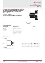
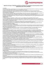
When the impact cylinder is instroked, line pressure will be<br />
under the piston holding it in position so closing the poppet<br />
(Figure 93).<br />
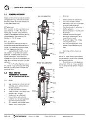
When the control valve is<br />
operated the chamber on<br />
top of the piston is<br />
pressurised and the<br />
volume under the piston<br />
is vented. The area ratio<br />
of the poppet orifice to<br />
the annular area under the<br />
piston is approximately 1<br />
to 9. This means that the<br />
pressure ratio in the<br />
cylinder must be more<br />
than 9 on top of the<br />
piston, to 1 under the Figure 93: Impact cyl and valve<br />
piston, before the piston<br />
can start moving. This gives a slight pause after operating the<br />
control valve while the pressures are attaining this ratio. At a<br />
line pressure of 5.5 bar the pressure under the piston must<br />
drop to below 0.6 bar before the piston starts to move. As soon<br />
as it does so the poppet valve is open and the effective area<br />
presented to the charged volume on top is instantly expanded<br />
by nine times. This sudden application of force coupled with<br />
very little back pressure under the piston gives rise to the rapid<br />
acceleration. If the cylinder is freely operated it will reach a max<br />
velocity at about 75mm of stroke and then completely cushion<br />
itself. The cushion is created by the small amount of air that<br />
remains under the piston. This is compressed at a faster rate<br />
than it can escape through the port in the front end cover. This<br />
cushioning effect is useful to have for a cylinder that is fired<br />
freely, otherwise it would destroy itself. In most applications<br />
however, the piston and rod will be brought to a dead stop by<br />
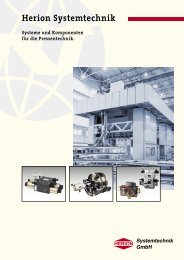
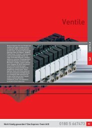
the tooling at the end of the working stroke. The graph (Figure<br />
94) shows typical kinetic energy characteristics of the<br />
Energy(%)<br />
200<br />
150<br />
100<br />
50<br />
0<br />
Figure 94: Energy graph<br />
10 bar (150 psig)<br />
7 bar (100 psig)<br />
5,5 bar (80 psig)<br />
4 bar (60 psig)<br />
2,7 bar (40 psig)<br />
0 25 50 75 100 125 150<br />
Stroke (mm)<br />
31<br />
piston and rod against stroke at varying line pressures.<br />
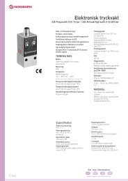
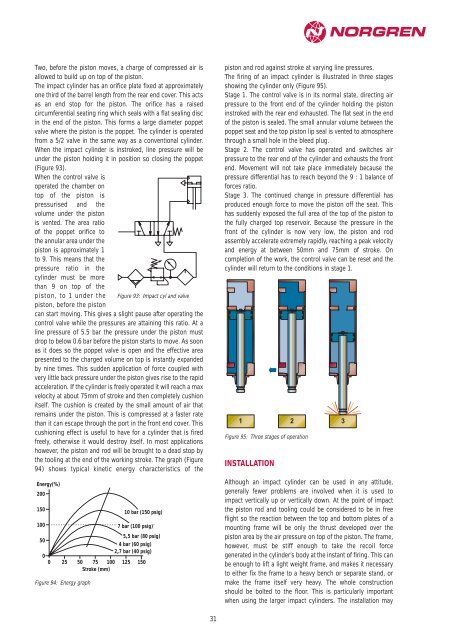
The firing of an impact cylinder is illustrated in three stages<br />
showing the cylinder only (Figure 95).<br />
Stage 1. The control valve is in its normal state, directing air<br />
pressure to the front end of the cylinder holding the piston<br />
instroked with the rear end exhausted. The flat seat in the end<br />
of the piston is sealed. The small annular volume between the<br />
poppet seat and the top piston lip seal is vented to atmosphere<br />
through a small hole in the bleed plug.<br />
Stage 2. The control valve has operated and switches air<br />
pressure to the rear end of the cylinder and exhausts the front<br />
end. Movement will not take place immediately because the<br />
pressure differential has to reach beyond the 9 : 1 balance of<br />
forces ratio.<br />
Stage 3. The continued change in pressure differential has<br />
produced enough force to move the piston off the seat. This<br />
has suddenly exposed the full area of the top of the piston to<br />
the fully charged top reservoir. Because the pressure in the<br />
front of the cylinder is now very low, the piston and rod<br />
assembly accelerate extremely rapidly, reaching a peak velocity<br />
and energy at between 50mm and 75mm of stroke. On<br />
completion of the work, the control valve can be reset and the<br />
cylinder will return to the conditions in stage 1.<br />
1 2 3<br />
Figure 95: Three stages of operation<br />
INSTALLATION<br />
Although an impact cylinder can be used in any attitude,<br />
generally fewer problems are involved when it is used to<br />
impact vertically up or vertically down. At the point of impact<br />
the piston rod and tooling could be considered to be in free<br />
flight so the reaction between the top and bottom plates of a<br />
mounting frame will be only the thrust developed over the<br />
piston area by the air pressure on top of the piston. The frame,<br />
however, must be stiff enough to take the recoil force<br />
generated in the cylinder’s body at the instant of firing. This can<br />
be enough to lift a light weight frame, and makes it necessary<br />
to either fix the frame to a heavy bench or separate stand, or<br />
make the frame itself very heavy. The whole construction<br />
should be bolted to the floor. This is particularly important<br />
when using the larger impact cylinders. The installation may