Actuator Guide - Norgren Pneumatics. Motion Control Equipment ...
Actuator Guide - Norgren Pneumatics. Motion Control Equipment ...
Actuator Guide - Norgren Pneumatics. Motion Control Equipment ...

You also want an ePaper? Increase the reach of your titles
YUMPU automatically turns print PDFs into web optimized ePapers that Google loves.
CLAMPING APPLICATIONS<br />
In a clamping application the force is developed as the cylinder<br />
stops. This is when the pressure differential across the piston<br />
reaches a maximum. The only losses from the theoretical<br />
thrust will be those caused by friction. These can be assumed<br />
to be acting even after the piston has stopped. As a general<br />
rule, make an allowance of 10% for friction. This may be more<br />
for very small bore cylinders and less for very large ones.<br />
If the cylinder is operating vertically up or down the mass of<br />
any clamping plates will diminish or augment the clamping<br />
force.<br />
DYNAMIC APPLICATIONS<br />
The actual thrust and speed from a moving cylinder are<br />
determined by friction and the rate at which air can flow in and<br />
out of the cylinder’s ports. The thrust or pull developed is<br />
divided into two components. One for moving the load, the<br />
other for creating a back pressure to help expel the air on the<br />
exhausting side of the piston.<br />
For a lightly loaded cylinder, most of the thrust is used to expel<br />
the back pressure and will result in a moderately fast speed.<br />
This is self limiting however as the faster the speed, the less<br />
will be the pressure differential across the piston. This is due<br />
to the increasing resistance through the ports, tubing, fittings<br />
and valve as the rate of flow increases.<br />
For a heavily loaded cylinder most of the thrust is used to move<br />
the load. The exhausting pressure will fall considerably to give a<br />
higher pressure differential before movement starts. The<br />
acceleration and speed will be determined by the inertia of the<br />
load and rate at which the lower back pressure is expelled. A<br />
heavy load simply diverts a greater proportion of the power of<br />
the cylinder away from creating a back pressure to moving the<br />
load. Although the speed for a heavily loaded cylinder is going to<br />
be slower it is not unreasonably so, providing the cylinder has<br />
been correctly chosen. As a general rule, the estimated thrust<br />
requirement should be between 50% and 75% of the theoretical<br />
thrust. This should give sufficient back pressure for a wide range<br />
of adjustable speed control when fitting flow regulators.<br />
9<br />
PISTON ROD BUCKLING<br />
Some applications require very long stroke cylinders. If there is<br />
a compressive axial load applied to the piston rod, care must<br />
be taken to ensure that the system parameters of length,<br />
diameter and load are within the safety limits to prevent<br />
buckling.<br />
There was a long standing belief that cylinder stroke lengths<br />
were limited to a maximum of 15 times the diameter of the<br />
bore. Whilst this gave a general indication of maximum stroke<br />
length, it did not take into account mounting support factors.<br />
In many instances the nature of the application and the style of<br />
mounting to be used allow greater stroke lengths, whilst in<br />
others the stroke length is considerably less.<br />
To calculate maximum stroke length the following formula<br />
should be used:<br />
F k =<br />
L 2 π<br />
. S<br />
2 . E . J<br />
Where<br />
Fk = Permissible buckling force in Newtons<br />
E = Modulus of Elasticity<br />
J = Moment of Inertia<br />
L = Effective length in millimetres<br />
S = Safety factor, normally 5<br />
One of the elements in this formula, Effective length, needs<br />
some explanation.<br />
Effective length x support factor = MAX STROKE LENGTH<br />
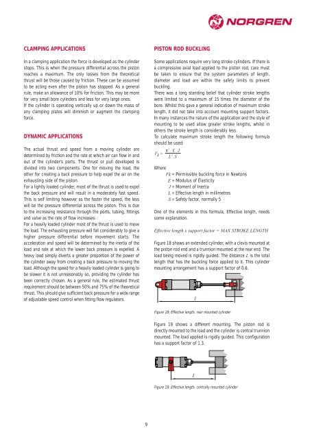
Figure 18 shows an extended cylinder, with a clevis mounted at<br />
the piston rod end and a trunnion mounted at the rear end. The<br />
load being moved is rigidly guided. The distance L is the total<br />
length that has the buckling force applied to it. This cylinder<br />
mounting arrangement has a support factor of 0.6.<br />
Figure 18: Effective length, rear mounted cylinder<br />
Figure 19 shows a different mounting. The piston rod is<br />
directly mounted to the load and the cylinder is central trunnion<br />
mounted. The load applied is rigidly guided. This configuration<br />
has a support factor of 1.3.<br />
l<br />
l<br />
Figure 19: Effective length, centrally mounted cylinder