Actuator Guide - Norgren Pneumatics. Motion Control Equipment ...
Actuator Guide - Norgren Pneumatics. Motion Control Equipment ...
Actuator Guide - Norgren Pneumatics. Motion Control Equipment ...

Create successful ePaper yourself
Turn your PDF publications into a flip-book with our unique Google optimized e-Paper software.
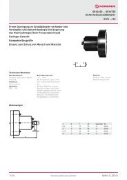
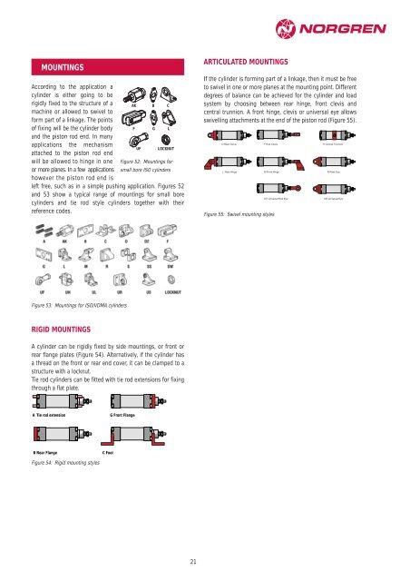
MOUNTINGS<br />
According to the application a<br />
cylinder is either going to be<br />
rigidly fixed to the structure of a<br />
machine or allowed to swivel to<br />
form part of a linkage. The points<br />
AK B C<br />
of fixing will be the cylinder body<br />
and the piston rod end. In many<br />
F G L<br />
applications the mechanism<br />
attached to the piston rod end<br />
UF LOCKNUT<br />
will be allowed to hinge in one Figure 52: Mountings for<br />
or more planes. In a few applications<br />
however the piston rod end is<br />
small bore ISO cylinders<br />
left free, such as in a simple pushing application. Figures 52<br />
and 53 show a typical range of mountings for small bore<br />
cylinders and tie rod style cylinders together with their<br />
reference codes.<br />
Figure 53: Mountings for ISO/VDMA cylinders<br />
RIGID MOUNTINGS<br />
A cylinder can be rigidly fixed by side mountings, or front or<br />
rear flange plates (Figure 54). Alternatively, if the cylinder has<br />
a thread on the front or rear end cover, it can be clamped to a<br />
structure with a locknut.<br />
Tie rod cylinders can be fitted with tie rod extensions for fixing<br />
through a flat plate.<br />
A Tie rod extension<br />
B Rear Flange<br />
Figure 54: Rigid mounting styles<br />
C Foot<br />
G Front Flange<br />
21<br />
ARTICULATED MOUNTINGS<br />
If the cylinder is forming part of a linkage, then it must be free<br />
to swivel in one or more planes at the mounting point. Different<br />
degrees of balance can be achieved for the cylinder and load<br />
system by choosing between rear hinge, front clevis and<br />
central trunnion. A front hinge, clevis or universal eye allows<br />
swivelling attachments at the end of the piston rod (Figure 55).<br />
D Rear Clevis F Rod Clevis<br />
H Central Trunnion<br />
L Rear Hinge M Front Hinge<br />
Figure 55: Swivel mounting styles<br />
UF Universal Rod Eye<br />
R Rear Eye<br />
UR Universal Eye