Fire-Lite Alarms MS-9600 Addressable Fire Control Panel
Fire-Lite Alarms MS-9600 Addressable Fire Control Panel
Fire-Lite Alarms MS-9600 Addressable Fire Control Panel
- No tags were found...

You also want an ePaper? Increase the reach of your titles
YUMPU automatically turns print PDFs into web optimized ePapers that Google loves.
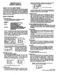
LOCA LCHARGERFLTHOT4XTM OPT BDCUT TOMONITOR 4XTMLCD DISPLAYNEUT EARTH+BATTERY-KEYPAD I/FOPT DACTOPT SLCInstallationSECTION 22.1 Mounting!See PageInstallationMountingThe cabinet may be either semi-flush or surface mounted. The cabinet mounts usingtwo key slots and two 0.250” (6.35 mm) diameter holes located in the backbox. Thekey slots are located at the top of the backbox and the two securing holes at the bottom.Carefully unpack the system and check for shipping damage. Mount the cabinet in aclean, dry, vibration-free area where extreme temperatures are not encountered. Thearea should be readily accessible with sufficient room to easily install and maintain thepanel. Locate the top of the cabinet approximately 5 feet (1.5 m) above the floor withthe hinge mounting on the left. Determine the number of conductors required for thedevices to be installed. Sufficient knockouts are provided for wiring convenience.Select the appropriate knockout(s) and pull the conductors into the box. All wiringshould be in accordance with the National and/or Local codes for fire alarm systems.The circuit board contains static-sensitive components. Always ground yourself with aproper wrist strap before handling any boards so that static charges are removed fromthe body. Use static suppressive packaging to protect electronic assemblies.✓ Mark and predrill holes in the wall for the top two keyhole mounting boltsusing the dimensions illustrated in Figure 2.2 on page 25✓ Install two upper fasteners in the wall with the screw heads protruding✓ Using upper ‘keyholes,’ place backbox over the two screws, level and secure✓ Mark and drill the lower two holes✓ Install remaining fasteners and tighten✓ Screw supplied standoffs onto mounting studs in locations indicated below✓ When the location is dry and free of construction dust, install the main circuitboard by aligning the 10 mounting holes in the circuit board with the 10mounting standoffs in the backbox as illustrated below✓ Secure the circuit board to the standoffs with the supplied screws and male/female standoff as indicated in following figureIMPORTANT!Secure circuit board to this standoff withsupplied male/female standoff<strong>MS</strong>-<strong>9600</strong> Main Circuit BoardTB3JP3CUT TODISABLEJP10TB4 TB5 TB6 TB7 TB8JP11JP5JP2DISABLEGNDJ17J16CB1JP6TB1J6TB2J2J8SW1J7J396brdmnt.cdrmounting studsmounting studs<strong>MS</strong>-<strong>9600</strong> BackboxFigure 2.1 <strong>MS</strong>-<strong>9600</strong> Main Circuit Board Installation24 <strong>MS</strong>-<strong>9600</strong> PN 51335:D 11/06/01