Fire-Lite Alarms MS-9600 Addressable Fire Control Panel
Fire-Lite Alarms MS-9600 Addressable Fire Control Panel
Fire-Lite Alarms MS-9600 Addressable Fire Control Panel
- No tags were found...

Create successful ePaper yourself
Turn your PDF publications into a flip-book with our unique Google optimized e-Paper software.
PN: 51335:D ECN 01-535<strong>Fire</strong> Alarm <strong>Control</strong> <strong>Panel</strong><strong>MS</strong>-<strong>9600</strong>/<strong>MS</strong>-<strong>9600</strong>EIMPORTANT! The SLC Manual Document #51309 must be referenced in addition to thismanual when installing or servicing the <strong>Fire</strong> Alarm <strong>Control</strong> <strong>Panel</strong>.Document #5133511/06/01 Revision:D
<strong>Fire</strong> Alarm System LimitationsAn automatic fire alarm system–typically made up of smokedetectors, heat detectors, manual pull stations, audible warningdevices, and a fire alarm control with remote notificationcapability–can provide early warning of a developing fire.Such a system, however, does not assure protection againstproperty damage or loss of life resulting from a fire.The Manufacturer recommends that smoke and/or heat detectorsbe located throughout a protected premise following therecommendations of the current edition of the National <strong>Fire</strong>Protection Association Standard 72 (NFPA 72),manufacturer's recommendations, State and local codes, andthe recommendations contained in the Guide for Proper Useof System Smoke Detectors, which is made available at nocharge to all installing dealers. A study by the Federal EmergencyManagement Agency (an agency of the United Statesgovernment) indicated that smoke detectors may not go off inas many as 35% of all fires. While fire alarm systems are designedto provide early warning against fire, they do not guaranteewarning or protection against fire. A fire alarm systemmay not provide timely or adequate warning, or simply may notfunction, for a variety of reasons:Smoke detectors may not sense fire where smoke cannotreach the detectors such as in chimneys, in or behind walls, onroofs, or on the other side of closed doors. Smoke detectorsalso may not sense a fire on another level or floor of a building.A second-floor detector, for example, may not sense afirst-floor or basement fire.Particles of combustion or "smoke" from a developing firemay not reach the sensing chambers of smoke detectors because:• Barriers such as closed or partially closed doors, walls, orchimneys may inhibit particle or smoke flow.• Smoke particles may become "cold," stratify, and not reachthe ceiling or upper walls where detectors are located.• Smoke particles may be blown away from detectors by airoutlets.• Smoke particles may be drawn into air returns beforereaching the detector.The amount of "smoke" present may be insufficient to alarmsmoke detectors. Smoke detectors are designed to alarm atvarious levels of smoke density. If such density levels are notcreated by a developing fire at the location of detectors, thedetectors will not go into alarm.Smoke detectors, even when working properly, have sensinglimitations. Detectors that have photoelectronic sensingchambers tend to detect smoldering fires better than flamingfires, which have little visible smoke. Detectors that have ionizing-typesensing chambers tend to detect fast-flaming firesbetter than smoldering fires. Because fires develop in differentways and are often unpredictable in their growth, neithertype of detector is necessarily best and a given type of detectormay not provide adequate warning of a fire.Smoke detectors cannot be expected to provide adequatewarning of fires caused by arson, children playing withmatches (especially in bedrooms), smoking in bed, and violentexplosions (caused by escaping gas, improper storage offlammable materials, etc.).While a fire alarm system may lower insurancerates, it is not a substitute for fire insurance!Heat detectors do not sense particles of combustion andalarm only when heat on their sensors increases at a predeterminedrate or reaches a predetermined level. Rate-of-riseheat detectors may be subject to reduced sensitivity over time.For this reason, the rate-of-rise feature of each detectorshould be tested at least once per year by a qualified fire protectionspecialist. Heat detectors are designed to protectproperty, not life.IMPORTANT! Smoke detectors must be installed in thesame room as the control panel and in rooms used by the systemfor the connection of alarm transmission wiring, communications,signaling, and/or power. If detectors are not so located,a developing fire may damage the alarm system, cripplingits ability to report a fire.Audible warning devices such as bells may not alert peopleif these devices are located on the other side of closed orpartly open doors or are located on another floor of a building.Any warning device may fail to alert people with a disability orthose who have recently consumed drugs, alcohol or medication.Please note that:• Strobes can, under certain circumstances, cause seizuresin people with conditions such as epilepsy.• Studies have shown that certain people, even when theyhear a fire alarm signal, do not respond or comprehend themeaning of the signal. It is the property owner's responsibilityto conduct fire drills and other training exercise to makepeople aware of fire alarm signals and instruct them on theproper reaction to alarm signals.• In rare instances, the sounding of a warning device cancause temporary or permanent hearing loss.A fire alarm system will not operate without any electricalpower. If AC power fails, the system will operate from standbybatteries only for a specified time and only if the batterieshave been properly maintained and replaced regularly.Equipment used in the system may not be technically compatiblewith the control. It is essential to use only equipmentlisted for service with your control panel.Telephone lines needed to transmit alarm signals from apremise to a central monitoring station may be out of serviceor temporarily disabled. For added protection against telephoneline failure, backup radio transmission systems are recommended.The most common cause of fire alarm malfunction is inadequatemaintenance. To keep the entire fire alarm system inexcellent working order, ongoing maintenance is required perthe manufacturer's recommendations, and UL and NFPA standards.At a minimum, the requirements of Chapter 7 of NFPA72 shall be followed. Environments with large amounts ofdust, dirt or high air velocity require more frequent maintenance.A maintenance agreement should be arrangedthrough the local manufacturer's representative. Maintenanceshould be scheduled monthly or as required by National and/or local fire codes and should be performed by authorized professionalfire alarm installers only. Adequate written recordsof all inspections should be kept.LimWarLg.p65 01/10/2000
Installation PrecautionsWARNING - Several different sources of power can be connectedto the fire alarm control panel. Disconnect all sourcesof power before servicing. <strong>Control</strong> unit and associated equipmentmay be damaged by removing and/or inserting cards,modules, or interconnecting cables while the unit is energized.Do not attempt to install, service, or operate this unit until thismanual is read and understood.CAUTION - System Reacceptance Test after SoftwareChanges. To ensure proper system operation, this productmust be tested in accordance with NFPA 72 Chapter 7 afterany programming operation or change in site-specific software.Reacceptance testing is required after any change, additionor deletion of system components, or after any modification,repair or adjustment to system hardware or wiring.All components, circuits, system operations, or software functionsknown to be affected by a change must be 100% tested.In addition, to ensure that other operations are not inadvertentlyaffected, at least 10% of initiating devices that are notdirectly affected by the change, up to a maximum of 50 devices,must also be tested and proper system operation verified.This system meets NFPA requirements for operation at0-49° C/32-120° F and at a relative humidity of 85% RH (noncondensing)at 30° C/86° F. However, the useful life of thesystem's standby batteries and the electronic componentsmay be adversely affected by extreme temperature rangesand humidity. Therefore, it is recommended that this systemand all peripherals be installed in an environment with a nominalroom temperature of 15-27° C/60-80° F.Verify that wire sizes are adequate for all initiating andindicating device loops. Most devices cannot tolerate morethan a 10% I.R. drop from the specified device voltage.Adherence to the following will aid in problem-freeinstallation with long-term reliability:Like all solid state electronic devices, this system mayoperate erratically or can be damaged when subjected to lightning-inducedtransients. Although no system is completelyimmune from lightning transients and interferences, propergrounding will reduce susceptibility. Overhead or outsideaerial wiring is not recommended, due to an increased susceptibilityto nearby lightning strikes. Consult with the TechnicalServices Department if any problems are anticipated orencountered.Disconnect AC power and batteries prior to removing or insertingcircuit boards. Failure to do so can damage circuits.Remove all electronic assemblies prior to any drilling, filing,reaming, or punching of the enclosure. When possible, makeall cable entries from the sides or rear. Before making modifications,verify that they will not interfere with battery, transformer,and printed circuit board location.Do not tighten screw terminals more than 9 in-lbs.Over-tightening may damage threads, resulting in reducedterminal contact pressure and difficulty with screw terminalremoval.Though designed to last many years, system componentscan fail at any time. This system contains static-sensitivecomponents. Always ground yourself with a proper wrist strapbefore handling any circuits so that static charges are removedfrom the body. Use static-suppressive packagingto protect electronic assemblies removed from the unit.Follow the instructions in the installation, operating, andprogramming manuals. These instructions must be followedto avoid damage to the control panel and associatedequipment. FACP operation and reliability depend uponproper installation by authorized personnel.FCC WarningWARNING: This equipment generates, uses, and canradiate radio frequency energy and if not installed andused in accordance with the instruction manual, maycause interference to radio communications. It hasbeen tested and found to comply with the limits for classA computing device pursuant to Subpart B of Part 15 ofFCC Rules, which is designed to provide reasonableprotection against such interference when operated in acommercial environment. Operation of this equipment ina residential area is likely to cause interference, in whichcase the user will be required to correct the interferenceat his own expense.Canadian RequirementsThis digital apparatus does not exceed the Class Alimits for radiation noise emissions from digitalapparatus set out in the Radio Interference Regulationsof the Canadian Department of Communications.Le present appareil numerique n'emet pas de bruitsradioelectriques depassant les limites applicables auxappareils numeriques de la classe A prescrites dans leReglement sur le brouillage radioelectrique edicte par leministere des Communications du Canada.LimWarLg.p65 01/10/2000
Notes4 <strong>MS</strong>-<strong>9600</strong> PN 51335:D 11/06/01
Table of ContentsSECTION 1: Product Description ........................................................................................................................121.1: Inventory .....................................................................................................................................................121.2: Features and Options...................................................................................................................................121.3: Specifications ..............................................................................................................................................141.3.1: Current Availability...........................................................................................................................151.4: <strong>Control</strong>s and Indicators ...............................................................................................................................161.5: Circuits ........................................................................................................................................................171.6: Components.................................................................................................................................................171.6.1: Intelligent <strong>Addressable</strong> Detectors: Newer Series..............................................................................181.6.2: Intelligent <strong>Addressable</strong> Modules: Newer Series...............................................................................191.6.3: 300 Series Intelligent <strong>Addressable</strong> Devices......................................................................................201.6.4: <strong>Addressable</strong> Device Accessories.......................................................................................................201.7: Optional Modules........................................................................................................................................201.8: Accessories..................................................................................................................................................211.8.1: PK-<strong>9600</strong> Programming Utility..........................................................................................................211.8.2: Dress <strong>Panel</strong>........................................................................................................................................211.8.3: Battery Box .......................................................................................................................................211.8.4: CHG-120F Battery Charger ..............................................................................................................221.8.5: Annunciators .....................................................................................................................................221.9: Getting Started.............................................................................................................................................23SECTION 2: Installation .......................................................................................................................................242.1: Mounting .....................................................................................................................................................242.2: Power...........................................................................................................................................................272.2.1: AC Power and Earth Ground Connection.........................................................................................272.2.2: Battery Power....................................................................................................................................272.2.3: DC Power Output Connection ..........................................................................................................272.3: Relays..........................................................................................................................................................282.4: Notification Appliance Circuits ..................................................................................................................282.5: UL Power-limited Wiring Requirements ....................................................................................................292.6: Optional Modules and Devices ...................................................................................................................302.6.1: 4XTMF Transmitter Module Installation..........................................................................................312.6.2: Auxiliary Trouble Input (J16 & J17).................................................................................................322.6.3: SLC-2 Expander Module ..................................................................................................................332.6.4: Printer/PC..........................................................................................................................................342.6.5: Digital Communicator and Annunciators .........................................................................................352.6.5.1 UDACT-F Digital Alarm Communicator/Transmitter ...........................................................352.6.5.2 ACM-8RF Relay <strong>Control</strong> Module ..........................................................................................352.6.5.3 BRKT-<strong>9600</strong> Universal Bracket Installation ............................................................................352.6.5.4 ACM and AFM Series Annunciators ......................................................................................37SECTION 3: Programming ...................................................................................................................................383.1: Programming Data Entry ............................................................................................................................383.2: User Programming ......................................................................................................................................393.3: Initial Power-up...........................................................................................................................................403.4: Programming Screens Description..............................................................................................................403.5: Programming and Passwords ......................................................................................................................403.6: Master Programming Level.........................................................................................................................423.6.1: Point Program ...................................................................................................................................433.6.1.1 Detector Programming ............................................................................................................433.6.1.1.1 Add Detector ........................................................................................................................433.6.1.1.2 Delete Detector ....................................................................................................................443.6.1.1.3 Edit Detector ........................................................................................................................443.6.1.2 Module Programming .............................................................................................................53<strong>MS</strong>-<strong>9600</strong> P/N: 51335:D 11/06/01 5
Table of Contents3.6.1.2.1 Add Module .........................................................................................................................533.6.1.2.2 Delete Module ......................................................................................................................543.6.1.2.3 Edit Module Screen for Monitor Module .............................................................................553.6.1.2.4 Edit Module Screen for <strong>Control</strong> Modules ............................................................................633.6.2: Zone Setup.........................................................................................................................................703.6.2.1 Enable ......................................................................................................................................703.6.2.2 Disable .....................................................................................................................................713.6.2.3 Zone 97, 98 and 99 ..................................................................................................................713.6.2.4 Zones Installed ........................................................................................................................723.6.2.5 Zones Enabled .........................................................................................................................723.6.2.6 Zones Disabled ........................................................................................................................723.6.2.7 Zone Type ...............................................................................................................................733.6.3: Loop Setup ........................................................................................................................................743.6.3.1 Style .........................................................................................................................................743.6.3.2 Loop Protocol ..........................................................................................................................743.6.4: System Setup.....................................................................................................................................753.6.4.1 Trouble Reminder ...................................................................................................................753.6.4.2 Banner .....................................................................................................................................763.6.4.3 Time-Date ...............................................................................................................................773.6.4.3.1 Time .....................................................................................................................................773.6.4.3.2 Date ......................................................................................................................................783.6.4.3.3 Clock Format ........................................................................................................................783.6.4.3.4 Daylight Savings Time .........................................................................................................783.6.4.4 Timers .....................................................................................................................................793.6.4.4.1 PAS (Positive Alarm Sequence) Delay ................................................................................793.6.4.4.2 Pre-signal Delay ...................................................................................................................803.6.4.4.3 Waterflow Delay ..................................................................................................................803.6.4.4.4 AC Loss Delay .....................................................................................................................813.6.4.5 NAC (Notification Appliance Circuit) ....................................................................................813.6.4.5.1 Enabled .................................................................................................................................823.6.4.5.2 Type ......................................................................................................................................833.6.4.5.3 Silenceable ...........................................................................................................................833.6.4.5.4 Auto Silence .........................................................................................................................843.6.4.5.5 Coding ..................................................................................................................................843.6.4.5.6 Zone ......................................................................................................................................853.6.4.5.7 Silence Inhibited ...................................................................................................................853.6.4.5.8 Synced Type .........................................................................................................................853.6.4.6 Relays ......................................................................................................................................863.6.5: Autoprogram .....................................................................................................................................873.6.6: Verify Loops......................................................................................................................................883.6.7: History...............................................................................................................................................883.6.7.1 View Events ............................................................................................................................893.6.7.2 Erase History ...........................................................................................................................893.6.8: Walktest.............................................................................................................................................903.6.9: Option Modules................................................................................................................................913.6.9.1 Annunciators/UDACT ............................................................................................................913.6.9.2 Printer/PC ................................................................................................................................923.6.10: Password Change ............................................................................................................................933.6.11: Clear Program..................................................................................................................................943.6.12: Program Check................................................................................................................................953.7: Maintenance Programming Level ...............................................................................................................973.7.1: Disable Point .....................................................................................................................................983.7.2: History...............................................................................................................................................993.7.3: Program Check..................................................................................................................................1003.7.4: Walktest.............................................................................................................................................1016 <strong>MS</strong>-<strong>9600</strong> P/N: 51335:D 11/06/01
Table of Contents3.7.5: System...............................................................................................................................................1013.7.6: Zone Setup ........................................................................................................................................103SECTION 4: Operating Instructions ....................................................................................................................1054.1: <strong>Panel</strong> <strong>Control</strong> Buttons .................................................................................................................................1054.1.1: Acknowledge/Step ............................................................................................................................1054.1.2: Alarm Silence....................................................................................................................................1054.1.3: Drill/Hold 2 Sec ................................................................................................................................1054.1.4: Reset..................................................................................................................................................1054.2: LED Indicators ............................................................................................................................................1064.3: Normal Operation........................................................................................................................................1074.4: Trouble Operation .......................................................................................................................................1074.5: Alarm Operation..........................................................................................................................................1094.6: Supervisory Operation.................................................................................................................................1104.7: Process Monitor Operation..........................................................................................................................1114.8: Hazard Condition Operation .......................................................................................................................1114.9: Medical Alert Condition Operation.............................................................................................................1114.10: NAC Operation .........................................................................................................................................1114.11: Programmed Zone Operation ....................................................................................................................1124.12: Disable/Enable Operation .........................................................................................................................1124.13: Waterflow Circuits Operation ...................................................................................................................1124.14: Detector Functions ....................................................................................................................................1124.15: Time Functions: Real-Time Clock ............................................................................................................1124.16: Synchronized NAC Operation ..................................................................................................................1134.17: Coded Operation .......................................................................................................................................1134.18: Presignal ....................................................................................................................................................1134.19: Positive Alarm Sequence ..........................................................................................................................1144.20: Special System Timers ..............................................................................................................................1154.20.1: Silence Inhibit Timer.......................................................................................................................1154.20.2: Autosilence Timer...........................................................................................................................1154.20.3: Trouble Reminder ...........................................................................................................................1154.20.4: Waterflow Retard Timer..................................................................................................................1154.20.5: Alarm Verification (None or Two Minutes)....................................................................................1164.21: Walktest.....................................................................................................................................................1164.22: Read Status................................................................................................................................................1174.22.1: System Point ...................................................................................................................................1184.22.2: Zones...............................................................................................................................................1194.22.3: Power...............................................................................................................................................1204.22.4: Trouble Reminder ...........................................................................................................................1204.22.5: Timers..............................................................................................................................................1214.22.6: NAC ................................................................................................................................................1214.22.7: Relays..............................................................................................................................................1224.22.8: Program Check................................................................................................................................1224.22.9: History.............................................................................................................................................1224.22.10: Annunciators .................................................................................................................................1234.22.11: Printer/PC......................................................................................................................................1234.22.12: Print...............................................................................................................................................1244.22.13: Time-Date......................................................................................................................................126SECTION 5: Power Supply Calculations .............................................................................................................1275.1: Overview .....................................................................................................................................................1275.2: Calculating the AC Branch Circuit .............................................................................................................1275.3: Calculating the System Current Draw.........................................................................................................1285.3.1: Overview...........................................................................................................................................1285.3.2: How to Use Table 5.3 on page 129 to Calculate System Current Draw ...........................................1285.4: Calculating the Battery Size........................................................................................................................130<strong>MS</strong>-<strong>9600</strong> P/N: 51335:D 11/06/01 7
Table of Contents5.4.1: NFPA Battery Requirements .............................................................................................................1305.4.2: Selecting and Locating Batteries.......................................................................................................130APPENDIX A: Software Zones ............................................................................................................................131A.1: Correlations ...............................................................................................................................................131APPENDIX B: Default Programming .................................................................................................................139APPENDIX C: Wire Requirements .....................................................................................................................1408 <strong>MS</strong>-<strong>9600</strong> P/N: 51335:D 11/06/01
It is imperative that the installer understand the requirements of the Authority Having Jurisdiction(AHJ) and be familiar with the standards set forth by the following regulatory agencies:• Underwriters Laboratories Standards• NFPA 72 National <strong>Fire</strong> Alarm Code• CAN/ULC - S527M Standard for <strong>Control</strong> Units for <strong>Fire</strong> Alarm SystemsBefore proceeding, the installer should be familiar with the following documents.NFPA StandardsNFPA 72 National <strong>Fire</strong> Alarm CodeNFPA 70 National Electrical CodeUnderwriters Laboratories Documents:UL 38 Manually Actuated Signaling BoxesUL 217 Smoke Detectors, Single and Multiple StationUL 228 Door Closers–Holders for <strong>Fire</strong> Protective Signaling SystemsUL 268 Smoke Detectors for <strong>Fire</strong> Protective Signaling SystemsUL 268A Smoke Detectors for Duct ApplicationsUL 346 Waterflow Indicators for <strong>Fire</strong> Protective Signaling SystemsUL 464 Audible Signaling AppliancesUL 521 Heat Detectors for <strong>Fire</strong> Protective Signaling SystemsUL 864 Standard for <strong>Control</strong> Units for <strong>Fire</strong> Protective Signaling SystemsUL 1481 Power Supplies for <strong>Fire</strong> Protective Signaling SystemsUL 1610 Central Station Burglar Alarm UnitsUL 1638 Visual Signaling AppliancesUL 1971 Signaling Devices for Hearing ImpairedCAN/ULC - S524M Standard for Installation of <strong>Fire</strong> Alarm SystemsCAN/ULC S527M Standard for <strong>Control</strong> Units for <strong>Fire</strong> Alarm SystemsNote: <strong>MS</strong>-<strong>9600</strong>E is not ULC listed for Canadian applicationsOther:EIA-232E Serial Interface StandardEIA-485 Serial Interface StandardNEC Article 250 GroundingNEC Article 300 Wiring MethodsNEC Article 760 <strong>Fire</strong> Protective Signaling SystemsApplicable Local and State Building CodesRequirements of the Local Authority Having Jurisdiction (LAHJ)<strong>Fire</strong>-<strong>Lite</strong> Documents:<strong>Fire</strong>-<strong>Lite</strong> Device Compatibility Document #15384SLC Wiring Manual Document #51309AFM-16ATF & AFM-32AF Document #15970AFM-16AF Annunciator Document #15210ACS Series Annunciators Document #51480UDACT-F Communicator/Transmitter Document #50049CHG-120F Battery Charger Document #50888LDM Series Lamp Driver Modules Document #50055LCD-80F Remote <strong>Fire</strong> Annunciator Document #51338ACM-8RF Relay <strong>Control</strong> Module Document #50362<strong>MS</strong>-<strong>9600</strong> PN 51335:D 11/06/01 9
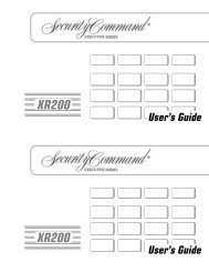
<strong>MS</strong>-<strong>9600</strong> Basic System ConnectionsDC Power Outputs (24 VDC)Supervise with a power supervision relay A77-716BNonresettable Power #2 - 24 VDC filtered,power-limited (3.00 amps maximum)Supervision required. Suitable forpowering annunciators.Nonresettable Power #1 - 24 VDC filtered,power-limited (3.00 amps maximum)Supervision required. Suitable forpowering annunciators.Resettable Power - 24 VDC filtered, power-limited(3.00 amps maximum) to smoke detectors (IDC).Supervision required.654321Notification Appliance CircuitsNAC #1Style Y (shown)or Style Z3.0 amps max.ELR 4.7K, ½W+ ++NAC #2Style Y orStyle Z (shown)3.0 amps max.+2 Programmable Relays &1 Fixed Trouble RelayContact Ratings:2.0 amps @ 30 VDC (resistive)0.5 amps @ 30 VAC (resistive)Contacts shown below in normalcondition (AC power with no alarm,trouble or supervisory activity).A Fail Safe Troublerelay switches to theNO position duringtrouble conditions andunder loss of all power.NC NO CEIA-232to printer orpersonal computerFor EDP-listed equipment orpersonal computer with FACPUpload/Download Utility.50 foot maximum within same room.5 4 3 2 19 8 7 6DB9FRedWhiteGreenOR13 12 11 10 9 8 7 6 5 4 3 2 125 24 23 22 21 20 19 18 17 16 15 14TERM(EIA-485)to LCD-80FTXRCVDTRGND+TB7 (option to DB-25)T R D G I I O OX CV TR ND N+ Ṉ UT+ UṮ+ACS (EIA-485)to ACS Annunc.or UDACT-F Black(power-limited,supervised) B A A Ḇ B A A Ḇ+ - + - + - + + - + + -Alarm* Trouble Supervisory*NO NC C NC NO C NO NC C + -A + A A -B+ Ḇ BshieldTB3JP3CUT TODISABLELOCALCHARGERCut this jumper to disable theFACP battery charger whenusing external charger.TB4 TB5 TB6 TB7(*CUT TOMONITOR 4XTMFJP6Factory default relay programmingas shown on circuit board )JP5TB84XTMF OPT BDJ10 J11Connectors for 4XTMF option moduleCut this jumper to enableSupervisory relay when4XTMF module is installedCut this jumper to supervisethe 4XTMF module wheninstalled (see JP10 & JP11)To disable ground fault detection,remove jumper/shunt from JP2JP2DISABLEGNDFLTJ2OPT DACTConnector for Optional 2ndSignalling Line Circuit ModuleOPT SLCJ17 J16LCD DISPLAYTB1 TB2J6 J8KEYPAD I/FSW1Flash Memory Load Enable Switch.UP is normal position for switch.DOWN position allows loading offactory software upgradesJ3<strong>9600</strong>layE.cdrCAUTION! HIGH VOLTAGECB1HOTNEUT EARTH120 VAC, 60 HZ, 3.2 amps220/240 VAC, 50 Hz, 1.6 amps+BATTERY-Battery24 VDC, 25 Amp Hour maximumJ7PS2 Keyboard InterfaceSLC LoopRefer to the SLC WiringManual for detailedinformation on wiringaddressable devicesfor Style 4, 6 and 7.10 <strong>MS</strong>-<strong>9600</strong> PN 51335:D 11/06/01
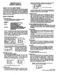
Ack/Step Sil ence Drill ResetHold 2 sec.1Peripheral Devices and Their Documents:AFM-16ATF &AFM-32AFDoc. # 15970ACM-16ATF &ACM-32ATFDoc. # 51480ACM-8RFDoc. # 50362ACS (EIA-485)AnnunciatorsUDACT-FDoc. # 50049AFM-16AFDoc. # 15210LDM-32FDoc. # 50055TERM (EIA-485)AnnunciatorsLCD-80FDoc. # 51338SLC Loop<strong>Addressable</strong> Devices and SLC WiringDoc. # 51309<strong>9600</strong>peri.cdrBattery ConnectorCHG-120F ChargerDoc. # 50888<strong>MS</strong>-<strong>9600</strong> PN 51335:D 11/06/01 11
Product DescriptionInventorySECTION 1Product DescriptionThe <strong>Fire</strong>•<strong>Lite</strong> <strong>MS</strong>-<strong>9600</strong> is a compact, cost effective, intelligent addressable FACP (<strong>Fire</strong>Alarm <strong>Control</strong> <strong>Panel</strong>) with an extensive list of powerful features. The combination of<strong>Fire</strong>•<strong>Lite</strong>’s newer series devices and legacy 300 Series devices, along with the <strong>MS</strong>-<strong>9600</strong>FACP, offer the latest in fire protection technology. The power supply and allelectronics are contained on a single circuit board housed in a metal cabinet, providinga complete fire control system for most applications. Optional modules, which pluginto the main circuit board, are available for special functions. Available accessoriesinclude LED, graphic and LCD annunciators, reverse polarity/city box transmitter,digital alarm communicator/transmitter, SLC expansion module, local and remoteupload/download software and remote power expansion. The <strong>MS</strong>-<strong>9600</strong>E offers thesame features as the <strong>MS</strong>-<strong>9600</strong> but allows connection to 220/240 VAC input.Note: Unless otherwise specified, the term <strong>MS</strong>-<strong>9600</strong> is used in this manual to refer toboth the <strong>MS</strong>-<strong>9600</strong> and the <strong>MS</strong>-<strong>9600</strong>E FACPs.1.1 Inventory1.2 Features and OptionsWhen the <strong>MS</strong>-<strong>9600</strong> shipment is received, check to make certain that all parts have beenincluded in the shipment. The <strong>MS</strong>-<strong>9600</strong> shipment should consist of one of each of thefollowing:✓ main circuit board with display✓ backbox with door✓ plastic bag containing screws, cables, key, etc.✓ manual• Single standard addressable SLC loop which meets NFPA Style 4, 6 and 7requirements• Optional module for adding a second SLC loop which meets NFPA Style 4, 6 and7 requirements• 318 addressable device capacity for each SLC loop (159 detectors and 159control/monitor modules)• 99 software zones• Two onboard NACs (Notification Appliance Circuits) with additional NACcapability using control modules• 6.0 amps total power for NACs and 24 VDC auxiliary power outputs• 7.2 amps total system power (includes battery charger)• Two programmable relay outputs and one fixed trouble relay• EIA-232 Printer/PC interface (variable baud rate)• 80-character LCD display (backlit)• Real-time clock/calendar with daylight savings time control• History file with 1,000 event capacity• Advanced fire technology features:✓ Automatic drift compensation✓ Maintenance alert✓ Detector sensitivity test capability (NFPA 72 compliant)✓ Automatic device type-code verification✓ Point trouble identification• Waterflow selection per module point12 <strong>MS</strong>-<strong>9600</strong> PN 51335:D 11/06/01
Features and OptionsProduct Description• Alarm verification selection per detector point• Walktest, silent or audible• PAS (Positive Alarm Sequence) and Pre-signal per point (NFPA 72 compliant)• Annunciators:✓ ACM Series-LED Zone Annunciators✓ LDM Graphic Annunciator Series✓ LCD-80F Liquid Crystal Display point annunciator✓ ACM-8RF Relay Module• Silence inhibit timer option per NAC• Autosilence timer option per NAC• Continuous, March Time, Temporal or California code for main circuit boardNACs with two-stage capability• Selectable strobe synchronization per NAC• Remote Acknowledge, Alarm Silence, Reset and Drill via addressable modules,AFM annunciators or LCD-80F Remote annunciator• Auto-program (learn mode) reduces installation time. Reports two devices set tothe same address• Password and key-protected nonvolatile memory• User programmable password• Fully programmable from local keypad or keyboard or local PC• SLC operates up to 10,000 ft. (3,000 m) with twisted, shielded wire or 3,000 ft(900 m) with untwisted, unshielded wire• Compatible with <strong>Fire</strong>•<strong>Lite</strong> newer series devices (CLIP Mode)✓ CP350: addressable Ionization Smoke Detector✓ SD350(T): addressable Photo Smoke Detector (T= with Thermal Sensor)✓ H350(R): Fast Response Heat Detector (R=Rate-of-Rise option)✓ D350P(R): addressable Photo Duct Detector (R=alarm relay option)✓ B501BH & B501BHT Sounder Base✓ BB224RB Relay Base✓ BB224BI Isolator Base✓ MMF-300: Monitor Module✓ MDF-300: Dual Monitor Module (uses two consecutive SLC addresses)✓ MMF-301: Miniature Monitor Module✓ MMF-302: 2-wire Detector Module✓ CMF-300: <strong>Control</strong> Module✓ CRF-300: Relay Module✓ BG-12LX: Manual Pull Station✓ I300: Isolator Module• Compatible with legacy <strong>Fire</strong>•<strong>Lite</strong> 300 Series devices (CLIP Mode only):✓ CP300: addressable Ionization Smoke Detector✓ SD300(T): addressable Photoelectric Smoke Detector (T= Thermal Sensor)✓ C304: <strong>Control</strong> Module✓ M300: Monitor Module✓ M301: Miniature Monitor Module✓ M302: 2-wire Detector Module✓ BG-10LX: Manual Pull Station• Optional 4XTMF module (conventional reverse polarity/city box transmitter)<strong>MS</strong>-<strong>9600</strong> PN 51335:D 11/06/01 13
Product DescriptionSpecifications1.3 SpecificationsAC Power - TB1<strong>MS</strong>-<strong>9600</strong>: 120 VAC, 50/60 Hz, 3.2 amps<strong>MS</strong>-<strong>9600</strong>E: 240 VAC, 50 Hz, 1.6 ampsWire size: minimum 14 AWG (2.00 mm 2 ) with 600 V insulationBattery (Lead Acid Only) - TB2Maximum Charging Circuit: Normal Flat Charge - 27.6 VDC @ 1.00 ampMaximum Battery Charger Capacity: 25 Amp Hour (<strong>MS</strong>-<strong>9600</strong> cabinet holds maximumof two 18 Amp Hour batteries. For greater than 25 Amp Hour up to 120 Amp Hourbatteries, use the CHG-120F Battery Charger and BB-55F Battery Box.Note: Jumper JP3, on the FACP main circuit board, must be cut to disable the FACPbattery charger when using the CHG-120F.Communication Loop - (Standard ) TB8 and (Optional SLC Expander Module) J324 VDC nominal, 27.6 VDC maximumMaximum length is 10,000 ft. (3,000 m) total twisted, shielded pair length or 3,000 ft.(900 m) untwisted, unshielded pair lengthMaximum loop current is 400 mA (short circuit) or 100 mA (normal)Maximum loop resistance is 40 ohmsSupervised and power-limitedRefer to SLC Loop manual for wiring informationNotification Appliance Circuits - TB4Power-limited circuitryMaximum voltage drop in wiring: 2.0 VDCNominal operating voltage: 24 VDCCurrent-limit: fuseless, electronic, power-limited circuitryMaximum signaling current per circuit: 3.00 amps (see Figure 1.1 on page 15)End-of-Line Resistor: 4.7 kΩ, ½ watt (P/N 71252 UL listed) for NACsRefer to <strong>Fire</strong>•<strong>Lite</strong> Device Compatibility Document for listed compatible devicesTwo Programmable and One Fixed Output Relay - TB5Contact rating: 2.0 amps @ 30 VDC (resistive), 0.5 amps @ 30 VAC (resistive)Form-C relaysRefer to Figure 2.5 on page 28 for information on power-limited wiring for relaycircuitsFour-Wire Resettable Smoke Detector Power (24 VDC nominal) - TB3,Terminals 1 (+) & 2 (-)Maximum ripple voltage: 10 mV R<strong>MS</strong>Up to 3.0 amps is available for powering 4-wire smoke detectors (see Figure 1.1)Power-limited circuitRefer to <strong>Fire</strong>•<strong>Lite</strong> Device Compatibility Document for listed compatible devicesNonresettable Power #1 (24 VDC Nominal) - TB3, Terminals 3 (+) & 4 (-)Maximum ripple voltage: 10mV R<strong>MS</strong>Total DC current available from each output is up to 3.00 amps (see Figure 1.1)Power-limited circuitNonresettable Power #2 (24 VDC Nominal) - TB3, Terminals 5 (+) & 6 (-)Maximum ripple voltage: 10mV R<strong>MS</strong>Total DC current available from each output is up to 3.00 amps (see Figure 1.1)Power-limited circuit14 <strong>MS</strong>-<strong>9600</strong> PN 51335:D 11/06/01
SpecificationsProduct DescriptionEIA-485 (ACS) - TB6ACS annunciator connector, Terminal 1 (+) and Terminal 2 (-)EIA-485 (TERM) - TB7Terminal Mode annunciator connector, Terminal 5 (In +), 6 (In -), 7 (Out +), 8 (Out -)EIA-232 (ACS) - TB7PC/Printer Connector, Terminal 1 (Transmit), 2 (Receive), 3 (DTR), 4 (Ground)Auxiliary Trouble Inputs - J16 & J17Two-pin connectors which can be used to monitor trouble conditions on auxiliaryequipment. They can be connected to the trouble bus of a peripheral such as theCHG-120F or to the normally-open dry contacts of a trouble relay.CAUTION! Do not connect power to these connectors since circuit damage may result.1.3.1 Current AvailabilityThe following figure illustrates the maximum current that is possible for each panelcircuit and the total current available from the FACP power supply.TB3Resettable Powerfor 4-WireSmoke DetectorsNonresettablePower # 1NonresettablePower # 21234563 amps maxper circuit3 amps maxper circuit3 amps maxper circuitStandby6 amps maxper panelNAC # 11233 amps maxper circuitAlarm7 amps maxper panel45NAC # 2673 amps maxper circuit8TB4powerdist.cdrRefer to the battery calculations section for additional information.Figure 1.1 Current Availability<strong>MS</strong>-<strong>9600</strong> PN 51335:D 11/06/01 15
Product Description<strong>Control</strong>s and Indicators1.4 <strong>Control</strong>s and IndicatorsLCD DisplayThe FACP uses an 80-character (4lines X 20 characters) high viewingangle LCD display. The displayincludes a long life LED backlightthat remains illuminated. If ACpower is lost and the system is not inalarm, the LED backlight will turn off to conserve batteries.LED IndicatorsLED indicators are provided to annunciate the following conditions:• AC Power (green)• <strong>Fire</strong> Alarm (red)• Supervisory (yellow)• Trouble (yellow)• Maintenance/presignal (yellow)• Alarm Silenced signals (yellow)• Disabled (yellow)• Battery fault (yellow)• Ground fault (yellow)Key <strong>Panel</strong>Mounted on the main circuit board, the key panel includes a window for the LCDdisplay and LED indicators as listed above. The key panel, which is visible with thecabinet door closed, has 25 keys, including a 16 key alpha-numeric pad similar to atelephone keypad.Function keys:• Acknowledge/Step• Alarm Silence• Drill• Reset (lamp test)1Service/program keys:• Keys labeled 1 to 94• * key• # key*• 0 (recall) key• 1st Event key• Clear key• Escape key• Mode key• Four cursor keys (up, down, left and right)• Enter keyFIRE-LITE ALAR<strong>MS</strong> INCSYSTEM ALL NORMAL10:00A 010101Local Piezo SounderA piezo sounder provides separate and distinct pulse rates for alarm, trouble andsupervisory conditions.250ABC36#DEFGHI JKL MNOPRS TUV WXYQZ -/.1 st EVENTCLR7 8 9 ESCRECALLMODEAC POWERFIRE ALAR<strong>MS</strong>UPERVISORYTROUBLEENTERMAINTENANCEALAR<strong>MS</strong>ILENCEDACK/STEPDISABLEDBATTERYGROUNDALAR<strong>MS</strong>ILENCEDRILLHOLD 2 SECRESETFigure 1.2 Membrane/Display <strong>Panel</strong><strong>9600</strong>kypd.cdr16 <strong>MS</strong>-<strong>9600</strong> PN 51335:D 11/06/01
CircuitsProduct Description1.5 CircuitsReferenceManualSLC Communication LoopOne SLC loop is provided standard on the FACP main circuit board. A second SLCloop is available by plugging the optional SLC module into connector J3 on the maincircuit board. SLC loops, configurable for NFPA Style 4, 6 or 7, providecommunication to addressable detectors, monitor (initiating device) and control (outputdevice) modules. Refer to the SLC Wiring manual for information on wiring devices.Output CircuitsThe following output circuits are available on the FACP:• 24 VDC Resettable (smoke detector power) output - 3.00 amps maximum• 24 VDC Nonresettable power output #1 - 3.00 amps maximum• 24 VDC Nonresettable power output #2 - 3.00 amps maximum• 24 VDC Battery Charger (up to 25 AH batteries)NAC (Notification Appliance Circuits)Two NACs, configurable for Style Y (Class B) or Style Z (Class A), are provided withvarious programmable features.RelaysOne fixed and two fully programmable Form-C dry contact relays are provided. Thefixed fail-safe relay monitors system trouble and the two programmable relays arefactory default programmed for system alarm and system supervisory. Contacts arerated 2.0 amps @ 30 VDC (resistive) and 0.5 amps @ 30 VAC (resistive). Theprogrammable relays can be programmed for the following operations:• fire alarm• trouble• supervisory• supervisory auto-resettable• DACT communication failure• process monitor• process monitor auto-resettable• hazard alert• medical alert• AC lossAuxiliary Trouble InputsAuxiliary Trouble Inputs can be connected to trouble bus outputs from auxiliaryequipment, such as power supplies or normally-open dry contacts of a trouble relay toallow monitoring by the <strong>MS</strong>-<strong>9600</strong>.1.6 ComponentsSee PageMain Circuit BoardThe main circuit board contains the system’s CPU, power supply, other primarycomponents and wiring interface connectors. Optional modules plug in and aremounted to the main circuit board. The circuit board is delivered in the <strong>MS</strong>-<strong>9600</strong> kitand must be mounted to the backbox. Refer to the circuit board illustration on Page 10.<strong>MS</strong>-<strong>9600</strong> PN 51335:D 11/06/01 17
CabinetThe <strong>MS</strong>-<strong>9600</strong> cabinet is red with a navy blue front overlay.The backbox provides space for two batteries (up to 18 AmpHour). Ample knockouts are provided for system wiring. Alsoincluded is a standard dress panel, which mounts to the insideof the cabinet (required on the ULC version). The dress panelmust be installed to meet FM requirements.BatteriesThe <strong>MS</strong>-<strong>9600</strong> cabinet provides space for two batteries (up to 18Amp Hour). Batteries larger than 18 Amp Hour up to 25 Amp Hour require use of the<strong>Fire</strong>•<strong>Lite</strong> BB-25F or similar UL listed battery cabinet. The CHG-120F can be used forcharging 25 to 120 AH batteries and the BB-55F can be used for housing the batteries.Batteries must be ordered separately.1.6.1 Intelligent <strong>Addressable</strong> Detectors: Newer SeriesIntelligent, addressable detectors provide information to the control panel on an SLCSignaling Line Circuit (refer to the SLC Wiring Manual for detailed information ondevice installation, wiring and operation). This allows the control panel to continuallyprocess the information to determine the status (alarm, trouble, maintenance or normal)of each detector. Each detector responds to an SLC address that is set in the detectorhead using built-in rotary decimal switches with the ability to select up to 159addresses. Note that a blinking LED on an intelligent detector indicatescommunication between the detector and the control panel. Refer to the <strong>Fire</strong>•<strong>Lite</strong>Device Compatibility Document for a list of approved detectors.Smoke Detectors (Photoelectric)The SD350 is an intelligent, addressable low profile photoelectric smoke detectorwhich provides smoke sensing technology. The SD350T includes a 135 fixed thermalsensor.Smoke Detector (Ionization)The CP350 is an intelligent, addressable low profile ionization smoke detector whichmeasures the level of combustion products in its chamber using the ‘ionizationprinciple.’Smoke Detector (Duct)The D350P is an intelligent, addressable photoelectric duct smoke detector. TheD350RP includes an alarm relay.Heat DetectorsThe H350 is an intelligent heat detector with a thermistor sensing circuit for fastresponse, designed to provide open area protection with 50 foot (15 m) spacingcapability. The H350R incorporates a thermal Rate-of-Rise circuit of 15 F (9.4 C).Detector BasesThe B501BH is a standard sounder base and the B501BHT is a temporal tone sounderbase for intelligent, addressable smoke detectors.The B224RB is a relay base with one Form-C relay for intelligent, addressable smokedetectors. It may be used to control auxiliary functions.The B224BI is an isolator base for intelligent, addressable smoke detectors. Itfunctions similar to the I300 isolator module which allows loops to operate under faultconditions and automatically restore when the fault is removed.ms<strong>9600</strong>.cdr
ComponentsProduct Description1.6.2 Intelligent <strong>Addressable</strong> Modules: Newer SeriesReferenceManualThe newer series of <strong>Control</strong> Modules and Monitor Modules provide an interfacebetween the control panel and conventional notification and initiating devices. Eachmodule can be set to respond to an address with built-in rotary switches with the abilityto select up to 159 addresses (a tab on the address switch must be broken off to useaddresses 100-159). A blinking LED on a monitor module indicates communicationbetween the module and the control panel. These devices can also be used in CLIPMode (Classic Loop Interface Protocol) when installed on older systems. Refer to the<strong>Fire</strong>•<strong>Lite</strong> Device Compatibility Document for a list of approved notification andinitiating devices.Monitor ModulesThe MMF-300, MDF-300 and MMF-302 are addressable monitor modules formonitoring conventional initiating devices. The MMF-300 is used for normally opencontact alarm initiating devices, such as manual pull stations, four-wire smokedetectors, heat detectors, waterflow, security contacts and supervisory devices. TheMDF-300 is a dual monitor module (Class B only) which occupies two consecutiveSLC addresses, with each module functionally the same as the MMF-300. TheMMF-302 is used primarily for two-wire smokes detectors in addition to normally opencontact devices. The supervised IDCs (Initiating Device Circuits) can be wired to themodules as NFPA Style B (Class B) or Style D (Class A) circuits. The modules aresupplied with a thermoplastic cover for mounting to a 4-inch mounting box.Monitor Module (miniature)The MMF-301 is an addressable module that is functionally similar to an MMF-300 butoffered in a smaller package for mounting directly in the electrical box of the devicebeing monitored.<strong>Control</strong> ModuleThe CMF-300 is an addressable <strong>Control</strong> Module used to connect NACs (NotificationAppliance Circuits) to power and supervise compatible, UL-listed notificationappliances. The NACs can be wired to the module as supervised NFPA Style Y (ClassB) or Style Z (Class A) circuits. The modules are supplied with a thermoplastic coverfor mounting to a 4-inch square mounting box.Relay ModuleThe CRF-300 is a <strong>Control</strong> Relay Module which is functionally similar to the CMF-300but used as a Form-C relay module.Isolator ModuleThe I300 loop isolator module is an automatic switch which opens the circuit voltage tothe SLC loop branch(es) whenever a wire-to-wire short circuit is detected on that loop.The remainder of the communications loop leading up to the I300 will continue tooperate, unaffected by the short. The isolator module is bidirectional, meaning that itcan detect a fault condition between the input SLC terminals or output SLC terminals.The I300 is required to meet NFPA Style 7 requirements.Detector AnnunciatorThe RA400Z is a remote single LED annunciator that can be wired directly to anaddressable detector for annunciation of that detector’s alarm status.Manual Pull StationThe BG-12LX is an addressable manual pull station featuring a key-lock reset. Thepull station responds to an address set by the installer using the built-in rotary decimalswitches on the pull station. The manual pull station includes a <strong>Fire</strong>•<strong>Lite</strong> key.<strong>MS</strong>-<strong>9600</strong> PN 51335:D 11/06/01 19
Product DescriptionOptional Modules1.7 Optional Modules1.6.3 300 Series Intelligent <strong>Addressable</strong> Devices<strong>Fire</strong>•<strong>Lite</strong>’s 300 Series Intelligent <strong>Addressable</strong> Devices are fully compatible with the<strong>MS</strong>-<strong>9600</strong> FACP. The devices must be configured for CLIP Mode operation if thecontrol panel is installed in an existing system with 300 Series devices. The address of300 Series devices cannot be set above 99. Compatible devices include:• SD300 Photoelectric Detector• SD300T Photoelectric Detector with Thermal Sensor• CP300 Ionization Detector• M300 Monitor Module• M301 Miniature Monitor Module• M302 2-wire Monitor Module• C304 <strong>Control</strong>/Relay Module• BG-10LX Manual Pull Station1.6.4 <strong>Addressable</strong> Device AccessoriesEnd-of-Line Resistor Assembly <strong>Fire</strong>•<strong>Lite</strong> P/N R-47KThe 47 kΩ End-of-Line Resistor assembly (P/N: R-47K) is used to supervise theMMF-300, MDF-300, MMF-301 and CMF-300 module circuits. The 3.9 kΩ End-of-Line Resistor assembly is used to supervise the MMF-302 module circuit. The resistorsare included with each module.Power Supervision RelayThe UL listed End-of-Line power supervision relay is used to supervise the power to 4-wire smoke detectors and notification appliances.N-ELR Mounting PlateThe N-ELR is a single End-of-Line resistor plate which is required for use in Canada.An ELR, which is supplied with each module and fire alarm control panel, is mountedto the ELR plate. Resistors mounted to the N-ELR plate can be used for the supervisionof a monitor and control module circuit.The <strong>MS</strong>-<strong>9600</strong> main circuit board includes option module connectors for the followingmodules:4XTMF Transmitter ModuleThe 4XTMF provides a supervised output for local energy municipal box transmitter,alarm and trouble reverse polarity. It includes a disable switch and disable troubleLED. A jumper on the module is used to select an option which allows the reversepolarity circuit to open with a system trouble condition if no alarm condition exists.The module plugs into connectors J10 and J11 which are located near the top center ofthe main circuit board. When the 4XTMF module is installed, Jumper JP6, on the maincircuit board, must be cut to allow supervision of the module.SLC-2 Expander ModuleThe SLC-2 Expander Module allows expansion of the <strong>MS</strong>-<strong>9600</strong> from one SLC circuitto two SLC circuits. The module plugs into connector J3 which is located in the lowerright corner of the main circuit board. The wiring for the second SLC connects toterminals located on the expander module.20 <strong>MS</strong>-<strong>9600</strong> PN 51335:D 11/06/01
AccessoriesProduct Description1.8 Accessories1.8.1 PK-<strong>9600</strong> Programming UtilityThe PK-<strong>9600</strong> Programming Utility can be used to program an <strong>MS</strong>-<strong>9600</strong> directly frommost IBM compatible computers, including laptops and portables, equipped with aserial port. <strong>MS</strong>-<strong>9600</strong> program files can also be created and stored on the PC and thendownloaded to the control panel. The PK-<strong>9600</strong> Kit includes the <strong>MS</strong>-<strong>9600</strong> WindowsbasedProgramming Utility software on CD-ROM with on-line help file. A serial cable(P/N: PRT/PK-CABLE), which must be purchased separately, is required forconnection of the PC to the RS-232 (PC/Printer) terminals at TB7 of the <strong>MS</strong>-<strong>9600</strong> maincircuit board. Refer to the illustration on page 10 and the section titled "Printer/PC" onpage 34, for the location and connections to this terminal.1.8.2 Dress <strong>Panel</strong>A dress panel is provided standard with the <strong>MS</strong>-<strong>9600</strong> (required for Canadianinstallations). The dress panel restricts access to the system wiring while allowingaccess to the key panel.Note that the <strong>MS</strong>-<strong>9600</strong> FACP, installed with the dress panel, has received FactoryMutual (FM) approval. FM approval is contingent on the proper installation of thedress panel.CAUTION: HIGH VOLTAGE UNDER PANEL!! WARNING !!SEVERAL DIFFERENT SOURCES OF POWERCAN BE CONNECTED TO THIS CONTROL UNITDISCONNECT ALL SOURCES OF POWER BEFORE SERVICING1.8.3 Battery BoxBB-17FThe BB-17F battery box may be used to house up to two 18 AH batteries in the eventthat room is not available in the main cabinet due to the use of a UDACT-F, 411UD,etc. The battery box mounts directly below the FACP cabinet. The battery box is redand is provided with knockouts.bb-17f.cdrdp<strong>9600</strong>.cdr<strong>MS</strong>-<strong>9600</strong> PN 51335:D 11/06/01 21
Product DescriptionAccessoriesBB-55FThe BB-55F battery box may be used to house two 25 AH batteries, two 60 AHbatteries or one 100 AH battery. When the CHG-120F is mounted in the BB-55F, two25 AH or one 60 AH battery may also be housed in the battery box.bb-55f.cdr1.8.4 CHG-120F Battery ChargerReferenceManualReferenceManualThe CHG-120F is capable of charging up to 120 AH lead-acid batteries with the <strong>MS</strong>-<strong>9600</strong> FACP. The FACP battery charger must be disabled when using the CHG-120F.The batteries and charger can be housed in the <strong>Fire</strong>•<strong>Lite</strong> BB-55F battery box which canbe mounted up to 20 feet away from the control panel. Note that when using the BB-55F for housing the charger and batteries greater than 25AH, multiple BB-55Fs arerequired. Refer to the CHG-120F Manual for additional information.1.8.5 AnnunciatorsACM Series LED Zone Type AnnunciatorsThe ACM Series Annunciators remotely display alarm and trouble status as well assystem status. In addition, they can provide remote Acknowledge, Silence, Reset andDrill functions. For more detailed information, refer to the appropriate annunciatormanual. Following is a list of annunciators which can be used with the <strong>MS</strong>-<strong>9600</strong>.• ACM-16ATF Annunciator <strong>Control</strong> Module annunciates 16 zones with 16 redalarm LEDs and 16 yellow trouble LEDs. In addition, it has a System TroubleLED, an On Line/Power LED and a local piezo sounder. It also has switches forFACP Acknowledge, Silence, Reset and Drill. It has rotary address switches andwill accept up to three AEM-16ATF Expanders• AEM-16ATF Annunciator Expander Module annunciates 16 zones with 16 redalarm LEDs and 16 yellow trouble LEDs• AFM-16ATF Annunciator Fixed Module annunciates 16 zones with 16 red alarmLEDs and 16 yellow trouble LEDs. In addition, it has a System Trouble LED, anOn Line/Power LED and a local piezo sounder. It also has switches for FACPAcknowledge, Silence, Reset and Drill. It is fixed at address ‘1’• ACM-32AF Annunciator <strong>Control</strong> Module annunciates 32 alarm zones with 32red LEDs. In addition, it has a System Trouble LED, an On Line/Power LEDand a local piezo sounder. It also has a switch for local piezo silence. It hasrotary address switches and will accept one AEM-32AF Expander• AEM-32AF Annunciator Expander Module annunciates 32 alarm zones with 32red LEDs• AFM-16AF Annunciator Fixed Module annunciates 16 alarm zones with 16 redalarm LEDs. In addition, it has a System Trouble LED, an On Line/Power LEDand a local piezo sounder. It also has a switch for local piezo silence. It is fixedat address ‘1’• AFM-32AF Annunciator Fixed Module annunciates 32 alarm zones with 32 redLEDs22 <strong>MS</strong>-<strong>9600</strong> PN 51335:D 11/06/01
Getting StartedProduct DescriptionReferenceManualReferenceManualLCD-80F Remote <strong>Fire</strong> AnnunciatorThe LCD-80F annunciator is a compact 80-character backlit LCD remote fireannunciator that is capable of displaying English language text. It mimics the displayon the control panel and will annunciate device type, point alarm, trouble orsupervisory condition, zone assignment plus any custom alpha labels programmed intothe FACP. The annunciator also provides system status LEDs to display AC Power,Alarm, Trouble, Supervisory and Alarm Silenced conditions. Additionally, the LCD-80F is capable of remotely performing critical system functions such as Acknowledge,Silence, Reset and Drill.Communications between the control panel and the annunciator is accomplished over aserial interface employing the EIA-485 communication standard. Up to 32 LCD-80Fannunciators may be connected to the EIA-485 circuit. The annunciators may bepowered from the host FACP or a remote UL listed filtered power supply such as the<strong>Fire</strong>•<strong>Lite</strong> FCPS Series. For more detailed information, refer to the LCD-80F manual.LDM Series Lamp Driver Modules (Graphic Annunciator)The LDM Series Lamp Driver Modules, which consist of the LDM-32F master andLDM-E32F expander modules, are used to provide an interface to a custom graphicLED annunciator. The master module provides power and control for a maximum ofthree expander modules. The LDM-32F and LDM-E32F have output connectors whichare used to drive lamps or LEDs and input connectors which are used for remote switchfunctions. Refer to the LDM Series Lamp Driver Modules manual for a completedescription.1.9 Getting StartedThe following is a brief summary of the minimal steps involved in bringing an<strong>MS</strong>-<strong>9600</strong> on-line:• Install Backbox and Main Circuit Board (refer to "Mounting" on page 24)• Address and Install Intelligent Devices (refer to the SLC Wiring Manual)• Enter Autoprogramming (refer to "Autoprogram" on page 87)• Resolve Programming Conflicts• Go to Point Program to Enter Specific Data (refer to "Point Program" on page43). Use the right and left arrow keys to navigate between devices.<strong>MS</strong>-<strong>9600</strong> PN 51335:D 11/06/01 23
LOCA LCHARGERFLTHOT4XTM OPT BDCUT TOMONITOR 4XTMLCD DISPLAYNEUT EARTH+BATTERY-KEYPAD I/FOPT DACTOPT SLCInstallationSECTION 22.1 Mounting!See PageInstallationMountingThe cabinet may be either semi-flush or surface mounted. The cabinet mounts usingtwo key slots and two 0.250” (6.35 mm) diameter holes located in the backbox. Thekey slots are located at the top of the backbox and the two securing holes at the bottom.Carefully unpack the system and check for shipping damage. Mount the cabinet in aclean, dry, vibration-free area where extreme temperatures are not encountered. Thearea should be readily accessible with sufficient room to easily install and maintain thepanel. Locate the top of the cabinet approximately 5 feet (1.5 m) above the floor withthe hinge mounting on the left. Determine the number of conductors required for thedevices to be installed. Sufficient knockouts are provided for wiring convenience.Select the appropriate knockout(s) and pull the conductors into the box. All wiringshould be in accordance with the National and/or Local codes for fire alarm systems.The circuit board contains static-sensitive components. Always ground yourself with aproper wrist strap before handling any boards so that static charges are removed fromthe body. Use static suppressive packaging to protect electronic assemblies.✓ Mark and predrill holes in the wall for the top two keyhole mounting boltsusing the dimensions illustrated in Figure 2.2 on page 25✓ Install two upper fasteners in the wall with the screw heads protruding✓ Using upper ‘keyholes,’ place backbox over the two screws, level and secure✓ Mark and drill the lower two holes✓ Install remaining fasteners and tighten✓ Screw supplied standoffs onto mounting studs in locations indicated below✓ When the location is dry and free of construction dust, install the main circuitboard by aligning the 10 mounting holes in the circuit board with the 10mounting standoffs in the backbox as illustrated below✓ Secure the circuit board to the standoffs with the supplied screws and male/female standoff as indicated in following figureIMPORTANT!Secure circuit board to this standoff withsupplied male/female standoff<strong>MS</strong>-<strong>9600</strong> Main Circuit BoardTB3JP3CUT TODISABLEJP10TB4 TB5 TB6 TB7 TB8JP11JP5JP2DISABLEGNDJ17J16CB1JP6TB1J6TB2J2J8SW1J7J396brdmnt.cdrmounting studsmounting studs<strong>MS</strong>-<strong>9600</strong> BackboxFigure 2.1 <strong>MS</strong>-<strong>9600</strong> Main Circuit Board Installation24 <strong>MS</strong>-<strong>9600</strong> PN 51335:D 11/06/01
MountingInstallation1.75“5.1 cm2.00“2.00“2.00“2.00“2.00“2.00“4.45 cm1.75“1.50“ (3.81 cm)3.79 cm1.49“1.62“ (4.11 cm)15.5“ (39.37 cm)12.00“ (30.48 cm)3.81 cm1.50“4.1 cm1.62“1.453“ (3.69 cm)4.1cm1.62“10.0“25.4 cm47.0cm18.5“17.35 cm6.83“4.45cm1.75“4.45cm1.75“1.50“3.81 cm4.37“11.1 cm4.1cm1.583“1.50“ (3.81 cm)11.1 cm4.37“<strong>9600</strong>encl.cdr1.75“4.45 cmFigure 2.2 <strong>MS</strong>-<strong>9600</strong> Cabinet Mounting<strong>MS</strong>-<strong>9600</strong> PN 51335:D 11/06/01 25
InstallationMountingTopDepth = 4.37" (11.1 cm)Door = 15.78" (40.08 cm)Backbox = 15.5" (39.37 cm)Depth =4.425"(11.24 cm)Door = 18.67" (47.43 cm)Backbox = 18.5" (47.0 cm)Left SideRight Side18.620"(47.3 cm)Bottom15.625"(39.688 cm)Depth = 4.75"(12.07 cm)18.625"(47.308 cm)21.620"(54.92 cm)Battery Box = 8.5"(21.59 cm)<strong>9600</strong>cab.cdrTrim RingP/N:FC-TRBattery Box = 14.34" (36.42 cm)Figure 2.3 <strong>MS</strong>-<strong>9600</strong> Cabinet Dimensions26 <strong>MS</strong>-<strong>9600</strong> PN 51335:D 11/06/01
Power2.2 PowerInstallationWARNING: Several different sources of power can be connected to this panel.Disconnect all sources of power before servicing. The panel and associated equipmentmay be damaged by removing and/or inserting cards, modules or interconnectingcables while this unit is energized.2.2.1 AC Power and Earth Ground ConnectionPrimary power required for the FACP is 120 VAC, 50/60 Hz,3.2 amps for the <strong>MS</strong>-<strong>9600</strong> or 220/240 VAC, 50/60 Hz, 1.6amps for the <strong>MS</strong>-<strong>9600</strong>E. Overcurrent protection for thiscircuit must comply with Article 760 of the NationalElectrical Code (NEC) and/or local codes. Use 14 AWG(2.00 mm 2 ) or larger wire with 600 volt insulation rating.Make certain that the AC mains circuit breaker is off beforeB1LCD DISPLAYTB1HOT NEUT EARTHTB2+BATTERYwiringany connections between the mains and the control panel. Connect wiring fromthe AC mains to TB1 on the FACP, being careful to observe proper connections.Connect a wire from the grounding stud in the cabinet to a known solid earth ground.This connection is vital for maintaining the control panel’s immunity to unwantedtransients generated by lightning and electrostatic discharge. Apply AC power to thepanel only after the system is completely installed and visually checked. Note that ACpower must be applied to the panel before installing the battery interconnect cable(refer to the following section).J6See Page2.2.2 Battery PowerBefore connecting the batteries to the FACP, makecertain that the interconnect cable between thebatteries is not connected. Do not connect theinterconnect cable until the system is completelyinstalled. Observe polarity when connecting the batteries. Connect the battery cable toTB2 on the main circuit board. Refer "Power Supply Calculations" on page 127, forcalculation of the correct battery rating.WARNING: Battery contains sulfuric acid which can cause severe burns to the skinand eyes and can destroy fabrics. If contact is made with sulfuric acid, immediatelyflush the skin or eyes with water for 15 minutes and seek immediate medical attention.-++-InterconnectCable2.2.3 DC Power Output ConnectionAll DC power outputs are power-limited.Power-limited Resettable Power3.0 amperes max., 24 VDC nominalfiltered, resettable power can be drawnfrom TB3 Terminals 1(+) and 2(-)Power-limited Nonresettable Power #13.0 amperes max. , 24 VDC nominalfiltered, nonresettable power can bedrawn from TB3 Terminals 3(+) and 4(-)Power-limited Nonresettable Power #23.0 amperes max. , 24 VDC nominalfiltered, nonresettable power can bedrawn from TB3 Terminals 5(+) and 6(-)+ - + - + -1 2 3 4 5 6<strong>9600</strong>tb3.cdrFigure 2.4 Power Outputs - 24 VDC<strong>MS</strong>-<strong>9600</strong> PN 51335:D 11/06/01 27
Installation2.3 RelaysRelaysThe FACP provides two programmable Form-C relays and one fixed fail-safe Form-Ctrouble relay, all with contacts rated for 2.0 amps @ 30 VDC (resistive) or 0.5 amps @30 VAC (resistive). The Alarm and Supervisory silk-screen labels reflect the factorydefault programming for the two programmable relays.Note that relay connections may be power-limited or nonpower-limited, provided that0.25” spacing is maintained between conductors of power-limited and nonpowerlimitedcircuits. Refer to UL Power-limited wiring requirements.Note that the relays labeled as AlarmRelay (Relay 1) and Supervisory Relay(Relay 3) reflect the factory defaultprogramming for these relays which areprogrammable.The relay labeled Trouble Relay (Relay 2)is fixed and cannot be changed. It is a failsaferelay which will transfer on anytrouble or total power failure.TB5ALARMRELAYTROUBLERELAYSUPVRELAYNO NC C NC NO C NO NC CRelay contacts shown with power applied to panel andno active troubles, alarms or supervisoriesFigure 2.5 Relay Terminals<strong>9600</strong>reyp.cdr2.4 Notification Appliance CircuitsSee PageReferenceManualThe control panel provides two NAC (Notification Appliance Circuits) configurable forStyle Y/Class B or Style Z/Class A. Each circuit is capable of 3.0 amps of current.Total system current cannot exceed 7.2 amps (refer to "Calculating the System CurrentDraw" on page 128). Use UL listed 24 VDC notification appliances only. Circuits aresupervised and power-limited. Refer to the <strong>Fire</strong>•<strong>Lite</strong> Device Compatibility Documentfor a listing of compatible notification appliances. The two NACs, which are locatedon the main circuit board, may be expanded via the <strong>Fire</strong>•<strong>Lite</strong> FCPS Series field charger/power supplies. Surge protection for notification appliances may be provided by usingone of the UL listed compatible surge suppressors listed in the <strong>Fire</strong>•<strong>Lite</strong> DeviceCompatibility Document.Style Z (Class A) Notification Appliance Circuit,supervised and power-limitedPolarized Bell +Style Y (Class B) Notification Appliance Circuit, supervisedand power-limited - 4.7 kohm, ½ watt P/N:71252 UL listed+Polarized BellPolarized Strobe+Polarized HornPolarized Horn++Polarized HornNotification Appliance Circuitpolarity shown in alarm state1 2 3 4 5 6 7 8TB4B+ A+ A- B- B+ A+ A- B-Figure 2.6 NAC ConnectionsDummy Load all unused circuit<strong>9600</strong>nac.cdr28 <strong>MS</strong>-<strong>9600</strong> PN 51335:D 11/06/01
UL Power-limited Wiring RequirementsInstallation2.5 UL Power-limited Wiring RequirementsPower-limited and nonpower-limited circuit wiring must remain separated in thecabinet. All power-limited circuit wiring must remain at least 0.25” (6.35 mm) awayfrom any nonpower-limited circuit wiring and nonpower-limited circuit wiring mustenter and exit the cabinet through different knockouts and/or conduits. A typical wiringdiagram for the <strong>MS</strong>-<strong>9600</strong> is shown below.Power-limited CircuitsNonpower-limitedCircuitsPower-limited Circuits4XTMFAC PowerNonpower-limitedTo EIA-485 and24 VDC powerrouted behindboardSLC-2Power-limitedCircuitsTo BatteriesNonpower-limitedCircuitsUDACT-FPower-limitedCircuits<strong>9600</strong>wireroute.cdrFigure 2.7 Typical UL Power-limited Wiring Requirements<strong>MS</strong>-<strong>9600</strong> PN 51335:D 11/06/01 29
InstallationOptional Modules and Devices2.6 Optional Modules and DevicesWARNING! Disconnect all sources of power (AC and DC) before installing orremoving any modules or wiring.<strong>MS</strong>-<strong>9600</strong> Keypad/Display RemovalRemoval of the keypad/display is normally not necessary. If, however, it becomesnecessary to replace the keypad/display, access the auxiliary trouble bus connectors atJ16 and J17 or install future option modules, the Keypad/Display can be removed byinserting a Phillips screwdriver into each of the three holes located in the flexiblecovering of the Keypad/Display and loosening the three mounting screws. Note that itis not necessary to disconnect the cables between the Keypad/Display and the maincircuit board unless the unit itself is being replaced. Carefully lift the Keypad/Displayand rest the unit at the bottom of the main circuit board.Mounting Screw Access HoleTB3JP3TB4 TB5 TB6 TB7 TB8CUT TODISABLELOCALCHARGERJP104XTM OPT BDJP6JP5AC POWERFIRE ALAR<strong>MS</strong>UPERVISORYTROUBLEMAINTENANCEALAR<strong>MS</strong>ILENCEDDISABLEDBATTERYGROUNDJP21 2 3 JP8 1 stDISABLEABCDEFEVENTJP7GND4 5 6FLTCLRCUT TOGHI JKL MNOMONITOR 4XTMJ17 7 J168 9 JP6 ESCJ6PRS TUV WXY* 0LCD DISPLAY#TB1 TB2MODEQZ -/.RECALLACK/STEPJ2ALARMOPT DACT SILENCEENTERDRILLJ8HOLD 2 SECJP412KEYPAD I/F RESET 3OPT SLCJ3CB1HOTNEUT EARTH+BATTERY-J7Mounting Screw Access Holes96dact1.cdrFigure 2.8 Keypad/Display Removal30 <strong>MS</strong>-<strong>9600</strong> PN 51335:D 11/06/01
2.6.1 4XTMF Transmitter Module InstallationThe 4XTMF provides a supervised output for a local energy municipal box transmitterin addition to alarm and trouble reverse polarity. A jumper option allows the reversepolarity circuit to open with a system trouble condition if no alarm condition exists. Adisable switch allows disabling of the transmitter output during testing to preventaccidental calling of the monitoring service.Local Energy Municipal Box Service (NFPA 72 Auxiliary <strong>Fire</strong> Alarm Systems):Supervisory Current: 5.0 mATrip Current: 350 mA (subtracted from notification appliance power)Coil Voltage: 3.65 VDCMaximum Coil Resistance: 14.6 ohmsMaximum allowable wire resistance between panel and trip coil: 3 ohmsMunicipal Box wiring can leave the buildingRemote Station Service (NFPA 72 Remote Station <strong>Fire</strong> Alarm Systems) - Intendedfor connection to a polarity reversal circuit or a Remote Station receiving unithaving compatible ratings:Maximum load for each circuit: 10 mAReverse polarity output voltage: 24 VDCRemote Alarm and Remote Trouble wiring can leave the buildingBefore installing the module, place the disconnect switch to the right (disconnect)position to prevent accidental activation of the municipal box. Note that a DisconnectLED will illuminate after the module is installed in the <strong>MS</strong>-<strong>9600</strong>. In addition, theSystem Trouble LED will turn on to indicate the Disconnect condition.Note: 4XTMF Module is not suitable fortransmitting reverse polarity supervisory signal.+ - + - + -1 2 3 4 5 6 7}Remote Alarm (power-limited)*}Remote Trouble (power-limited)*No connection}Municipal Box (nonpower-limited)*Polarities are shown for module activation* Wiring from theseterminals can exit theprotected premises.Dummy load terminals6 and 7 (4.7kΩ, ¼ wattresistor) if MunicipalBox is not connected.Disconnect LED4xtmfl.cdrDisconnect Switchshown in disconnectpositionTBL JumperConnect to FACP J10 & J11Figure 2.9 4XTMF Transmitter Module
The following steps must be followed when installing the 4XTMF module:1. Remove all power (AC and DC) from the FACP before installing 4XTMF2. Cut jumper JP6 on the main circuit board to allow the control panel to supervisethe 4XTMF module3. Carefully plug the connectors on the 4XTMF module into connectors J10 and J11on the <strong>MS</strong>-<strong>9600</strong> main circuit board, being careful not to bend any pins4. Secure 4XTMF module to standoffs with supplied screws.5. Reapply power to the FACP6. For proper 4XTMF operation, the output relays must be programmed for thefactory default settings as shown on the PC board silkscreen: Alarm Relay,Trouble Relay and Supervisory Relay7. When the installation has been complete, enable the 4XTMF module by slidingthe disconnect switch to the left8. Test system for proper operationStandoffTB3JP3StandoffTB4 TB5 TB6 TB74XTMFJ10 & J11 ConnectorsJ10CUT TOMONITOR 4XTM4XTM OPT BDJ11JP6JP5Cut Jumper JP6J2OPT DACTJ17J16J6J8SW1<strong>MS</strong>-<strong>9600</strong>CB1LCD DISPLAYTB1 TB2HOT NEUT EARTH +BATTERY-KEYPAD I/FJ79604xtm1.cdrFigure 2.10 4XTMF Connectors to <strong>MS</strong>-<strong>9600</strong> ConnectorsNOTE: Jumper JP5 on the <strong>MS</strong>-<strong>9600</strong> main circuit board can be used to configure the FACPsupervisory relay for operation with the 4XTMF module. The supervisory relay must beprogrammed as shown on the main circuit board silkscreen (TB5, Terminals 4, 5 & 6).Cutting JP5 will allow the 4XTMF to generate a trouble if the supervisory contact opensLeaving JP5 in will prevent generation of a trouble if the supervisory contact opens2.6.2 Auxiliary Trouble Input (J16 & J17)Auxiliary Trouble Inputs 1 (J17) and 2 (J16), which are located on the <strong>MS</strong>-<strong>9600</strong> maincircuit board, can be used to monitor for trouble conditions on auxiliary equipment suchas power supplies. J16 and/or J17 can be connected to any open collector troubleoutput on the auxiliary equipment. The <strong>MS</strong>-<strong>9600</strong> control panel will indicate a troublecondition if a trouble is sensed at the Auxiliary Trouble Inputs.If the 4XTMF Module is installed and jumper JP6 on the <strong>MS</strong>-<strong>9600</strong> has been cut tosupervise it, Auxiliary Trouble Input 1 (J17) will monitor the 4XTMF for troubleconditions.
2.6.3 SLC-2 Expander ModuleReferenceManualSee PageThe optional SLC-2 Expander Module provides a second SLC loop for the <strong>MS</strong>-<strong>9600</strong>control panel. This allows connection of an additional 318 addressable devices,bringing the total to 636 addressable devices which can be connected to the FACP.Refer to the SLC Manual for information on connecting devices to the SLC.The following steps must be followed when installing the SLC-2 Expander Module:1. Remove all power (AC and DC) from the FACP before installing the SLC-2module2. Carefully plug connector J3 on the SLC-2 module into connector J3 on the<strong>MS</strong>-<strong>9600</strong> main circuit board, being careful not to bend any pins3. Secure the SLC-2 Expander Module to the four standoffs on the FACP maincircuit board with the supplied screws4. Connect the SLC wiring and devices to TB8 on the SLC Expander Module.Refer to the SLC Manual for wiring information5. Reapply power to the control panel6. Program the addressable devices connected to the SLC-2 Expander Module asdetailed in "Master Programming Level" on page 427. Test the system for proper operationSLC Loop 1Shield BShield ASLC A-SLC B-SLC A+SLC B+SLC Loop 2Shield BShield ASLC A-SLC B-SLC A+SLC B+TB7 TB8 TB8OPT SLCJ3<strong>MS</strong>-<strong>9600</strong>J3SLC-2 Expander Module96optslc.cdrFigure 2.11 SLC-2 Expander Module Installation
!2.6.4 Printer/PCA serial printer or a PC (personal computer) may be connected to TB7 Terminals 1 - 4on the FACP. The printer can be used to provide a hard-copy printout of real-timeevents, history file and walktest data. An IBM compatible PC can be connected toprovide local FACP programming capabilities using the PK-<strong>9600</strong> programming utility.Installation of either device requires panel programming to allow the FACP tocommunicate with the device.CAUTION! Do not connect a printer or PC to the <strong>MS</strong>-<strong>9600</strong> FACP if a ground faultexists on the control panel. Circuit damage may result. Remove all power (AC andDC) before installing or removing any wiring.InstallationRemote printers and PCs require separate primary power. Also required is the PRT/PK-CABLE which is an interface cable prewired to a DB9F connector. Wire the PRT/PK-CABLE to TB7 Terminals 1 - 4 as illustrated in the following figure. Connect theDB9F connector to the printer or PC serial EIA-232 port. If a nine-pin serial connectoris not available on the printer or PC, use a DB25 adapter. Make certain that the DB25adapter does not swap the Transmit and Receive lines. Apply power to the FACP andprinter or PC. Note that a ground fault may occur on the FACP, dependent on theprinter or PC being used, due to this connection. For this reason, it is important thatthere be no preexisting ground fault on the panel.Note that the printer may or may not be supervised as determined by userprogramming. Refer to "Printer/PC" on page 92.5 4 3 2 19 8 7 6PRT/PK-CABLERedWhiteGreenBlackTB6ACS1 COMM 2TXRCVDTRGRNDRS-232 PC/PRINTERXMT RCV DTR GRNDTB7TB8SLC SLC SHIELDB+ A+ B- A- B AFigure 2.12 Serial Printer and Computer Connections<strong>9600</strong>tb7a.cdrPrinter ConfigurationRefer to the documentation supplied with the printer for pertinent information aboutprinter setup. Set the printer’s options as listed in the following table:COMMUNICATION SETUPBUFFER:LARGEDATA BITS: 7PARITY:EVENSTOP BIT:1 STOPBAUD RATE: 2400/4800/<strong>9600</strong>AUTOMATIC LINE FEED NOAUTOMATIC CARRIAGE RETURN NOPC ConfigurationThe Windows-based PK-<strong>9600</strong> Programming Utility Kit contains CD-ROM with on-linehelp file.
ABCDEFGHI JKL MNOPRS TUV WXYMODEHOLD 2 SECReferenceManualSee PageReferenceManual2.6.5 Digital Communicator and Annunciators2.6.5.1 UDACT-F Digital Alarm Communicator/Transmitter2.6.5.2 ACM-8RF Relay <strong>Control</strong> Module2.6.5.3 BRKT-<strong>9600</strong> Universal Bracket InstallationTB3JP3CUT TODISABLELOCALCHARGERTB4 TB5 TB6 TB7 TB8JP5JP104XTM OPT BDJP11AC POWERFIRE ALARMMAINTENANCEALAR<strong>MS</strong>ILENCEDSUPERVISORYTROUBLEDISABLEDBATTERYGROUNDJP2123 JP8ACK/STEP1 stDISABLEEVENTJP7GNDFLT 4 5 6 CLRCUT TOMONITOR 4XTMJ17 7 J168 9 JP6 ESCJ6*LCD DISPLAY0 #TB1 TB2QZ -/.RECALLCB1 HOT NEUT EARTH +BATTERY-J2ALARMOPT DACT SILENCEENTERJ8KEYPAD I/FDRILLJP412RESET 3J7J12OPT SLCJ3Mount BRKT-<strong>9600</strong> to PEMstuds on back of cabinetusing supplied hex nuts.<strong>MS</strong>-<strong>9600</strong> Cabinet96brkmnt.cdrFigure 2.13 BRKT-<strong>9600</strong> Bracket Installation
✓ UDACT-F Digital Alarm Communicator/Transmitter - installs at standofflocation (A)✓ ACM-8RF Annunciator <strong>Control</strong> Module (Relay) - installs at standoff location(A)1. Install the two supplied standoffs in location (A) as indicated in Step 1 of thefollowing illustration2. Position the module bottom in the slot located in the bottom of the BRKT-<strong>9600</strong>as indicated in Step 2 of the following illustration3. Secure the module to the standoffs installed in the top of the BRKT-<strong>9600</strong> withtwo mounting screws as indicated in Step 3 of the following illustration4. Refer to the appropriate module manual for detailed information on wiring themodule for power, communication, etc.5. Install a maximum of two 12 Amp Hour batteries with the orientation illustratedin Figure 2.13. Larger batteries require a separate UL listed battery box(A)BRKT-<strong>9600</strong> BRKT-<strong>9600</strong> BRKT-<strong>9600</strong>(A)standoffsmountingscrewsmodulemodule<strong>9600</strong>brkt.cdrSlot96brcksd.cdrStep 1 Step 2 Step 3Figure 2.14 BRKT-<strong>9600</strong> Module Installation Steps
2.6.5.4 ACM and AFM Series AnnunciatorsACM Annunciator Address Annunciator Displays the Following Points1 8 General System Status Points & Zones 1 - 562 Zones 57 - 99 & 2 NACs3 Loop 1, Module Addresses 1 - 644 Loop 2, Module Addresses 1 - 645 Loop 1, Module Addresses 65 - 1286 Loop 2, Module Addresses 65 - 1287 Loop 1, Module Addresses 129 - 159 & Loop 2 Module Addresses 129 - 1598 Loop 1, Detector Addresses 1 - 649 Loop 2, Detector Addresses 1 - 6410 Loop 1, Detector Addresses 65 - 12811 Loop 2, Detector Addresses 65 - 12812 Loop 1 Detector Addresses 129 - 159 & Loop 2 Detector Addresses 129 - 15913 not used14 not used15 not used16 not used17 not used18 not used19 not used20 8 General System Status Points & Zones 1 - 5621 Zones 57 - 99 & 2 NACs22 Loop 1, Module Addresses 1 - 6423 Loop 2, Module Addresses 1 - 6424 Loop 1, Module Addresses 65 - 12825 Loop 2, Module Addresses 65 - 12826 Loop 1, Module Addresses 129 - 159 & Loop 2 Module Addresses 129 - 15927 Loop 1, Detector Addresses 1 - 6428 Loop 2, Detector Addresses 1 - 6429 Loop 1, Detector Addresses 65 - 12830 Loop 2, Detector Addresses 65 - 12831 Loop 1 Detector Addresses 129 - 159 & Loop 2 Detector Addresses 129 - 15932 not used• General Alarm• General Trouble• General Supervisory• Alarm Silenced• System Off Normal• AC Loss• Battery Fault• NAC Fault
SECTION 3Programming3.1 Programming Data EntryProgramming can be accomplished using the <strong>MS</strong>-<strong>9600</strong> keypad or by connecting anoptional standard computer keyboard. The keyboard can be connected to the PS-2connector J7 on the control panel main circuit board.The information presented in this section refers to programming the <strong>MS</strong>-<strong>9600</strong> via theonboard keypad. If an optional computer keyboard is connected to the <strong>MS</strong>-<strong>9600</strong> maincircuit board, the following table describes the keyboard keys which correspond to theonboard keypad keys.Keypad Keys1st EventCLRESCRECALLComputer Keyboard KeysHomeDeleteEscInsert* *# #A - ZA - Z0 - 9 0 - 9• (on QZ key) Space bar— —/ /• •ENTEREnterNote: The main keypad function keys (ACK/STEP, ALARM SILENCE, DRILL andRESET) are not available on the keyboard.
3.2 User Programming!The <strong>MS</strong>-<strong>9600</strong> is completely field programmable and requires no special software skills.While programming the <strong>MS</strong>-<strong>9600</strong>, the fire protection capabilities of the control panelare enabled.Site-specific programming may be accomplished in three ways:• Autoprogramming Feature - This is a convenient method for quickly bringingthe FACP addressable SLC devices on-line without the necessity ofprogramming each device individually. Refer to "Autoprogram" on page 87 fora detailed description of Autoprogramming• Manual programming or editing, using the FACP keypad or a PC keyboard• Off-line Programming and Editing Feature - allows creation and editing of sitespecificcustom programs using a Windows-based computer. For programsrequiring a large amount of data entry, this method may be preferred. A PK-<strong>9600</strong>programming kit can be ordered for this purposeThe System All Normal screen will be displayed in a programmed system with no activealarms, troubles or supervisories, as illustrated below:FIRE-LITE ALAR<strong>MS</strong> INCSYSTEM ALL NORMAL10:00A 010801Programming and Read Status mode can be entered while the panel is in any mode ofoperation. If the panel is in alarm, the alarm condition must be acknowledged beforeentering any other mode. To access any of the programming or read status features, theEnter or Mode key must be pressed, which will cause the LCD to display the following:1=READ STATUS2=PROGRAMMINGSee PagePressing 1, while this screen is being displayed, will cause the control panel to enter theRead Status feature which allows the user to view the programmed features and statusof the control panel The Read Status feature is not password protected. Refer to "ReadStatus" on page 117 for a detailed description of this feature.Pressing 2 will select user Programming which may only be accomplished by anauthorized person. After pressing 2, a screen will prompt for a password. Afterentering the correct password, the user may select from a list of programming options.Exit Programming or Read StatusThe programmer can exit Read Status or Programming mode by repeatedly pressing thekeypad ESC (Escape) key until the display reads System All Normal. Note that thedata which is entered during Programming mode is not saved until the programmerexits this mode by repeatedly pressing the ‘ESC’ key. If the Reset key is pressed orpower is lost before exiting Programming mode, all data which was just entered will belost.
3.3 Initial Power-upUser Programming LevelsThere are two user programming levels:• User Master Program Level 1 is used for programming panel specific datarelating to device types, zoning, messages, control panel functions, etc.• User Maintenance Program Level 2 is used by a qualified operator to accessfeatures such as Disable/Enable, View and Clear History, Walktest and SystemTime Change.The following sections describe the initial programming procedures for a new system.The same procedures are used to modify programming in an existing system.After completing the wiring of addressable devices to the SLC, apply power to thecontrol panel. If the addressable devices have not yet been programmed into the FACP,their LEDs will not flash and the following trouble message will be displayed.TROUBL IN SYSTEMNO DEVICES INSTALLED09:03A 0108013.4 Programming Screens DescriptionSee PageTwo main options are available when the Enter key is pressed: Read Status andProgramming. Each option has multiple functions or features which may be chosen.To view all of the choices, it is necessary that the programmer scroll through a numberof additional subscreens. These selections are displayed on multiple screens to makethem more readable for the programmer. Refer to "Master Programming Level" onpage 42, for additional information on the various screens.The title of the main option screen will always be displayed at the top of the subscreensfor the programmer’s convenience. If additional subscreens exist, an Up or Downarrow will be displayed in the upper right corner of the screen being viewed. Theprogrammer can then press the keypad Up or Down arrow key to view the newsubscreen. To select one of the choices in a screen, the programmer presses the keypadnumerical key corresponding to the desired choice.Note that subscreens may also have multiple options which require viewing more thanone screen. The same process, as detailed in the previous paragraphs, is followed toview all option choices.3.5 Programming and PasswordsSee PageThere are two factory set programming passwords which will access the Programmingscreens as indicated in the following examples. From either of the screens, access tospecific system and device features or programming may be obtained. All userprogramming entries are stored in nonvolatile memory. The factory set passwords canbe changed by the user as described in "Password Change" on page 93. If an invalidpassword is entered, the blinking cursor will return to the first password characterposition. To exit Programming or Read Status mode at any time, press the ESC(Escape) key repeatedly. Note that Programming mode must be exited using the ESCkey in order to store the program data entered during this mode. If the Reset key ispressed or power is lost before exiting Programming mode, the data just entered willnot be saved.
To access user Programming mode, press the Enter or Mode key. The LCD will displaythe following:1=READ STATUS2=PROGRAMMINGTo enter the user Programming mode, press 2. The display will read as follows:PROGRAMMINGENTER PASSWORD*****Entering the Master level password (default 00000) will cause the following screen toappear:PROGRAMMING1=POINT PROGRAM2=ZONE SETUP3=LOOP SETUPIf the Maintenance level password (default 11111) is entered, the following screen willappear:PROGRAMMING1=POINT PROGRAM2=HISTORY3=PROGRAM CHECKNote that in the two preceding screens, an arrow appears to inform the programmer thatadditional options can be viewed by pressing the keypad down arrow key.
3.6 Master Programming LevelWhen the Master Program Level password is entered, the control panel will enter userProgramming mode. In this mode, the piezo sounder remains off, the trouble relay isactivated and the system Trouble LED flashes until Programming mode is exited. Thefollowing display will appear:PROGRAMMING1=POINT PROGRAM2=ZONE SETUP3=LOOP SETUPProgramming Screen #1The down arrow which appears in the display indicates that additional programmingchoices can be viewed by pressing the down arrow key on the keypad. If a down andup arrow appear in the display, pressing the ‘down’ arrow key will display thesubsequent Programming Screens as illustrated below while pressing the ‘up’ arrowkey will display the previous screen.PROGRAMMING1=SYSTEM SETUP2=AUTOPROGRAM3=VERIFY LOOPSProgramming Screen #2PROGRAMMING1=HISTORY2=WALKTEST3=OPTION MODULESProgramming Screen #3PROGRAMMING1=PASSWORD CHANGE2=CLEAR PROGRAM3=PROGRAM CHECKProgramming Screen #4
PROGRAMMING1=POINT PROGRAM2=ZONE SETUP3=LOOP SETUPProgramming Screen #13.6.1 Point ProgramThe Point Program option allows the programmer to add a new addressable device to anSLC loop, delete an existing device from a loop or change the programming for anexisting device. Pressing 1, while viewing Programming Screen #1, will select thePoint Program option and display the following screen:POINT PROGRA<strong>MS</strong>ELECT LOOP1=LOOP 12=LOOP 2Point Program Screen #1The programmer selects the desired SLC loop by pressing 1 or 2 in Point ProgramScreen #1, which causes the panel to display the following screen:POINT PROGRA<strong>MS</strong>ELECT TYPE1=DETECTOR2=MODULEPoint Program Screen #23.6.1.1 Detector ProgrammingDETECTOR1=ADD2=DELETE3=EDITDetector Screen3.6.1.1.1 Add DetectorADD DETECTORENTER DETECTOR#***Add Detector Screen
ADD DETECTORDETECTOR# 005IS ADDEDDETECTOR1=ADD2=DELETE3=EDIT3.6.1.1.2 Delete DetectorDetector ScreenDELETE DETECTORENTER DETECTOR#***Delete Detector ScreenDELETE DETECTORDETECTOR# 005IS DELETED3.6.1.1.3 Edit DetectorTEDIT DETECTORENTER POINT ADDRESS***Edit Detector Screen
NO DETECTORINSTALLEDEdit Detector Screen #1TROUBL SMOKE(PHOTO)********************ZNNN* 1D017Edit Detector Screen #1NORMAL SMOKE (PHOTO)*********************ZNNNV 1D017Edit Detector Screen #1✓ Normal - indicates that the detector with the selected address is physicallyinstalled on the SLC and communicating with the control panel (enabled)✓ - represents the adjective and noun, which have beenprogrammed, describing the location of the displayed device✓ ZNNN - represents the first of five possible software zones that the detector isassigned to (NNN = the three digit zone number from 000 - 099)✓ V or * - indicates whether or not alarm verification is enabled (V = alarmverification enabled and * = alarm verification disabled)✓ 1D017 - represents the Loop, Device type and Device address (1 = SLC Loop1, D=Detector and 017 = Detector Address 017)
smoke detector withaddress 017, located on the first SLC loop:EDIT DETECTOR 1D0171=ENABLEDYES2=TYPE SMOKE(PHOTO)3=VERIFICATION OFFEdit Detector Screen #2EDIT DETECTOR 1D0171=WALKTESTNO2=PASNO3=PRE-SIGNAL NOEdit Detector Screen #3EDIT DETECTOR 1D0171=ZONE ASSIGNMENT00 ** ** ** **Edit Detector Screen #4EDIT DETECTOR 1D0171=NOUN/ADJECTIVE2=DESCRIPTION********************Edit Detector Screen #5EDIT DETECTOR1=ENABLED2=TYPE3=VERIFICATIONEdit Detector Screen #2
EDIT DETECTOR1=ENABLED2=TYPE3=VERIFICATIONEdit Detector Screen #2DETECTOR TYPE1=SMOKE(PHOTO)2=SMOKE (ION)3=HEATDetector Type Screen #1DETECTOR TYPE1=SMOKE-DUCT-P2=SUPERV DUCTPDetector Type Screen #2EDIT DETECTOR1=WALKTEST2=PAS3=PRE-SIGNALEdit Detector Screen #3See PageSee Page
✓ Select PAS Yes when editing the detector set to address 005✓ Program the desired zone or zones to be activated by this detector, in thisexample Z001✓ Program an output, such as a control module that is to be activated by detector005 by assigning the same zone to it; in this example Z001✓ Program an output, such as a control module, for PAS activation by assigningzone Z97 to it. This control module may be connected to a signaling deviceused to indicate a PAS condition (do not use a Notification Appliance Circuitfor this purpose)✓ Enable zones Z001 and Special Purpose Zone PAS 97 and set the PAS delaytimer to some valueEDIT DETECTOR1=WALKTEST2=PAS3=PRE-SIGNALEdit Detector Screen #3See PageTo enable the Pre-signal feature,press 3 while viewing Edit Detector Screen #3 until the display reads Pre-signalYes. Each press of the 3 key will cause the display to toggle between Pre-signal Yesand Pre-signal No. Refer to .✓ Select Pre-signal Yes when editing the detector set to address 005✓ Program the desired zone or zones to be activated by this detector, in thisexample Z001✓ Program an output, such as a control module that is to be activated by detector005 by assigning the same zone to it; in this example Z001✓ Program an output, such as a control module, for Pre-signal activation byassigning zone Z98 to it. This control module may be connected to a signalingdevice used to indicate a Pre-signal condition ✓ Enable zones Z001 and Special Purpose Zone Pre-signal 98 and set the Presignaldelay timer to some value
EDIT DETECTOR1=ZONE ASSIGNMENT00 ** ** ** **Edit Detector Screen #4ZONE ASSIGNMENTZ00 Z** Z** Z** Z**Zone Assignment ScreenSee PageEDIT DETECTOR1=NOUN/ADJECTIVE2=DESCRIPTION*****************Edit Detector Screen #51=STANDARD ADJECTIVE2=STANDARD NOUN3=CUSTOM ADJECTIVE4=CUSTOM NOUNNoun/Adjective Screen
1=STANDARD ADJECTIVE2=STANDARD NOUN3=CUSTOM ADJECTIVE4=CUSTOM NOUNNoun/Adjective ScreenPress the number corresponding to the adjectivethat is to be used as a descriptor for the location of the detector currently beingprogrammed. When an adjective has been selected, it will appear at the top of thedisplay as indicated by the asterisks.**********************1=NORTH2=SOUTH3=EASTAdjective Screen #1**********************1=3RD2=4TH3=5THAdjective Screen #5**********************1=WEST2=FRONT3=CENTERAdjective Screen #2**********************1=FLOOR12=FLOOR23=FLOOR3Adjective Screen #6**********************1=REAR2=UPPER3=LOWERAdjective Screen #3**********************1=FLOOR42=FLOOR53=ROOMAdjective Screen #7*********************1=MAIN2=FIRST3=2NDAdjective Screen #4
1=STANDARD ADJECTIVE2=STANDARD NOUN3=CUSTOM ADJECTIVE4=CUSTOM NOUNNoun/Adjective ScreenPress the number corresponding to the noun that is tobe used as a descriptor for the location of the detector currently being programmed.When a noun has been selected, it will appear at the top of the display as indicatedby the asterisks.**********************1=BASEMENT2=BOILER RM3=CLASSROOMNoun Screen #1**********************1=KITCHEN2=LOBBY3=OFFICENoun Screen #5**********************1=CLOSET2=CORRIDOR3=ELECTRIC RMNoun Screen #2**********************1=PATIENT2=RESTROOM3=ROOMNoun Screen #6**********************1=ELEVATOR2=ENTRANCE3=FLOORNoun Screen #3**********************1=STAIRWAY2=STOREROOM3=WINGNoun Screen #7**********************1=GARAGE2=HALLWAY3=HVAC RMNoun Screen #4
1=STANDARD ADJECTIVE2=STANDARD NOUN3=CUSTOM ADJECTIVE4=CUSTOM NOUNNoun/Adjective ScreenEDIT DETECTOR1=NOUN/ADJECTIVE2=DESCRIPTIONEdit Detector Screen #5DESCRIPTION 1D0021=NOUN/ADJECTIVE********************Adjective/Noun Screen• If the zero key is pressed, a 0 is placed in the first letter position• If the zero key is then pressed a second time with no intervening key actions, theentire field is replaced with the field entered for the previous device programmed,and the cursor moves to the last character of the field (Recall function). TheRecalled Adjective or Noun field may now be changed letter-by-letter• If the zero key is pressed again with no other intervening key actions and the lastcharacter in the field is a number 0-9, the number is incremented by one. If thelast character is a letter, it changes to a 0. If the last character goes from 9 to 0and the characters to the left of the last character are also numbers, they are alsoincremented (overflow)• The above increment function may be repeated with each press of the zero key
1. The cursor is on the first letter of the Adjective field. Press the zero key twice todisplay FLR_32. With the cursor on the first letter of the Noun field, press the zero key twice torecall the display ROOM_304. The cursor automatically jumps from the first tothe last letter of the Noun field3. With the cursor on the last letter of the Noun field, press the zero key again toincrement the room number to 3054. Press the right arrow key to advance the zone field5. Select a zone number from 00 to 99. Z00 (default zone) is the general alarmzone. Z01 through Z99 may be selected to link software zonesPOINT PROGRA<strong>MS</strong>ELECT TYPE1=DETECTOR2=MODULEPoint Program Screen #23.6.1.2 Module ProgrammingMODULES1=ADD2=DELETE3=EDITModules Screen3.6.1.2.1 Add ModuleADD MODULEENTER MODULE#***Add Module Screen #1
ADD MODULE1=CONTROL2=MONITORAdd Module Screen #2ADD MODULEMODULE# 005IS ADDEDAdd Module Screen #3MODULES1=ADD2=DELETE3=EDITModules Screen3.6.1.2.2 Delete ModuleDELETE MODULEENTER MODULE#***Delete Module ScreenDELETE MODULEMODULE# 005IS DELETED
3.6.1.2.3 Edit Module Screen for Monitor ModuleEDIT MODULEENTER MODULE ADDRESS***Edit Module ScreenNO MODULEINSTALLEDEdit Module ScreenTROUBL MONITORZNNN1M012NORMAL MONITORZNNN1M012✓ Normal - indicates that the module with the selected address is physicallyinstalled on the SLC and communicating with the control panel (enabled)✓ - represents the adjective and noun, which have beenprogrammed, describing the location of the displayed device✓ ZNNN - represents the first of five possible software zones that the module isassigned to (NNN = the two digit zone number from 000 - 099)✓ 1M012 - represents the Loop, Device type and Device address (1 = SLC Loop1, M=Module and 012 = Module Address 012)
See PageNORMAL MONITORZNNN1M012EDIT MONITOR 1M0121=ENABLEDYES2=TYPE MONITOREdit Monitor Screen #2EDIT MONITOR1=PRE-SIGNAL2=PAS1M012NONOEdit Monitor Screen #3EDIT MONITOR 1M0121=WALKTESTYES2=ZONE ASSIGNMENT00 ** ** ** **Edit Monitor Screen #4EDIT MONITOR 1M0121=ADJECTIVE/NOUN2=DESCRIPTION********************Edit Monitor Screen #5
Master Programming LevelProgrammingEDIT MONITOR1=ENABLED2=TYPE MONITOREdit Monitor Screen #2Enable/Disable ModuleTo Enable or Disable the monitor module, press the 1 key while viewing the EditModule Screen #2. Each press of the key will toggle the screen between EnabledYes and Enabled No. If Enabled No is selected, the module will not be polled by thecontrol panel, preventing the module from reporting alarms and troubles to thepanel. The control panel will indicate a system trouble condition and the DisableLED with turn on if any devices are disabled.Type MonitorUsing the PK-<strong>9600</strong> Upload/Download utility program, unique user-defined monitortypes can be created and loaded into the FACP for later use. The FACP response tothe activation of a user-defined type is the same as most previous standard types inthe list, thus allowing a variety of user-defined types and responses. To select thetype of monitor module being programmed, press the 2 key while viewing the EditMonitor Screen #2. This will cause the control panel to display the followingMonitor Type Screens:MONITOR TYPE1=PULL-STATION2=USER-DEFINED-13=WATERFLOWMonitor Type Screen #1MONITOR TYPE1=USER-DEFINED-62=MEDIC-ALERT3=USER-DEFINED-7Monitor Type Screen #5MONITOR TYPE1=USER-DEFINED-22=MONITOR3=BLANKMonitor Type Screen #2MONITOR TYPE1=HAZARD-ALERT2=USER-DEFINED-83=TORNADO-ALERTMonitor Type Screen #6MONITOR TYPE1=USER-DEFINED-32=FUTURE USE3=USER-DEFINED-4Monitor Type Screen #3MONITOR TYPE1=USER-DEFINED-92=USER-DEFINED-103=USER-DEFINED-11Monitor Type Screen #7MONITOR TYPE1=SMOKE-CONVENTIONAL2=HEAT-DETECTOR3=USER-DEFINED-5Monitor Type Screen #4MONITOR TYPE1=TAMPER2=SUPERVISORY3=SUPERVISORY-ARMonitor Type Screen #8Note: For the SUPERVISORY-AR selection, AR refers to AutoResettable<strong>MS</strong>-<strong>9600</strong> PN 51335:D 11/06/01 57
ProgrammingMaster Programming LevelMONITOR TYPE1=POWER-MONITOR2=TROUBLE-MONITOR3=USER-DEFINED-12Monitor Type Screen #9MONITOR TYPE1=PROC-MON2=PROCMON-AR3=USER-DEFINED-13Monitor Type Screen #10MONITOR TYPE1=ACK-SWITCH2=SIL-SWITCH3=RESET-SWITCHMonitor Type Screen #11MONITOR TYPE1=DRILL-SWITCH2=PAS-BYPASS3=USER-DEFINED-14Monitor Type Screen #12Note: For the PROCMON-AR selection, PROCMON refers to Process Monitor and AR refers to AutoResettableWhile viewing one of the Monitor Type screens, select the type of monitor modulebeing programmed by pressing the corresponding keypad number key. The displaywill return to the Edit Monitor Screen #2 which will show the new type selection.Monitor module type selection will affect the function of the point as follows:Monitor TypePull-StationUser-Defined-1WaterflowUser-Defined-2MonitorBlankUser-Defined-3Future UseUser-Defined-4Smoke-ConventionalHeat-DetectorUser-Defined-5User-Defined-6Medic-AlertUser-Defined-7Hazard-AlertUser-Defined-8Tornado-AlertUser-Defined-9User-Defined-10User-Defined-11TamperSupervisorySupervisory-ARPower-MonitorTrouble-MonitorUser-Defined-12Proc-MonProcmon-AutoUser-Defined-13Ack-SwitchSil-SwitchReset-SwitchDrill-SwitchPAS-BypassUser-Defined-14Action When Activated<strong>Fire</strong> Alarm<strong>Fire</strong> Alarm<strong>Fire</strong> Alarm Delayed<strong>Fire</strong> Alarm Delayed<strong>Fire</strong> Alarm<strong>Fire</strong> Alarm<strong>Fire</strong> AlarmFuture UseSupervisory on partial short, <strong>Fire</strong> Alarm on full short<strong>Fire</strong> Alarm<strong>Fire</strong> Alarm<strong>Fire</strong> Alarm<strong>Fire</strong> AlarmSupervisory, latchingSupervisory, latchingSupervisory, latchingSupervisory, latchingSupervisory, latchingSupervisory, latchingSupervisory, latchingSupervisory, latchingSupervisory, nonlatching (tracking)Supervisory, latchingSupervisory, nonlatching (tracking)AC FaultTroubleTroublePiezoPiezo, nonlatching (tracking)Piezo, nonlatching (tracking)Acts like panel Acknowledge KeyActs like panel Alarm Silence KeyActs like panel Reset KeyActs like panel Drill KeyPAS DisablePAS Disable58 <strong>MS</strong>-<strong>9600</strong> PN 51335:D 11/06/01
EDIT MONITOR1=PRE-SIGNAL2=PASEdit Monitor Screen #3See PageSee PageEDIT MONITOR1=WALKTEST2=ZONE ASSIGNMENT00 ** ** ** **Edit Monitor Screen #4To enable the Pre-signal feature, press 1 while viewing Edit Monitor Screen #3 untilthe display reads Pre-signal Yes. Each press of the 1 key will cause the display totoggle between Pre-signal Yes and Pre-signal No. Refer to "Presignal" on page 113for additional information.MON ZONE ASSIGNZ00 Z** Z** Z** Z**Zone Assignment ScreenEDIT MONITOR1=NOUN/ADJECTIVE2=DESCRIPTION*****************Edit Monitor Screen #51=STANDARD ADJECTIVE2=STANDARD NOUN3=CUSTOM ADJECTIVE4=CUSTOM NOUNNoun/Adjective Screen
1=STANDARD ADJECTIVE2=STANDARD NOUN3=CUSTOM ADJECTIVE4=CUSTOM NOUNNoun/Adjective ScreenPressing 1 while viewing the Noun/Adjective Screen will cause the followingscreen(s) to be displayed. Note that the keyboard down arrow key must be pressedto see all the Adjective screens. Press the number corresponding to the adjectivethat is to be used as a descriptor for the location of the monitor module currentlybeing programmed.**********************1=NORTH2=SOUTH3=EASTAdjective Screen #1**********************1=3RD2=4TH3=5THAdjective Screen #5**********************1=WEST2=FRONT3=CENTERAdjective Screen #2**********************1=FLOOR 12=FLOOR 23=FLOOR 3Adjective Screen #6**********************1=REAR2=UPPER3=LOWERAdjective Screen #3**********************1=FLOOR 42=FLOOR 53=ROOMAdjective Screen #7**********************1=MAIN2=FIRST3=2NDAdjective Screen #4
1=STANDARD ADJECTIVE2=STANDARD NOUN3=CUSTOM ADJECTIVE4=CUSTOM NOUNNoun/Adjective ScreenPress the number corresponding to the noun that is tobe used as a descriptor for the location of the monitor module currently beingprogrammed.**********************1=BASEMENT2=BOILER RM3=CLASSROOMNoun Screen #1**********************1=KITCHEN2=LOBBY3=OFFICENoun Screen #5**********************1=CLOSET2=CORRIDOR3=ELECTRIC RMNoun Screen #2**********************1=PATIENT2=RESTROOM3=ROOMNoun Screen #6**********************1=ELEVATOR2=ENTRANCE3=FLOORNoun Screen #3**********************1=STAIRWAY2=STOREROOM3=WINGNoun Screen #7**********************1=GARAGE2=HALLWAY3=HVAC RMNoun Screen #4
EDIT MONITOR1=NOUN/ADJECTIVE2=DESCRIPTION*****************Edit Monitor Screen #5DESCRIPTION 1M0121=NOUN/ADJECTIVE********************Noun/Adjective Screen• If the zero key is pressed, a 0 is placed in the first letter position• If the zero key is then pressed a second time with no intervening key actions, theentire Adjective field is replaced with the field entered for the previous deviceprogrammed, and the cursor moves to the last character of the field (Recallfunction). The Recalled Adjective or Noun field may now be changed letter-byletter• If the zero key is pressed again with no other intervening key actions and the lastcharacter in the field is a number 0-9, the number is incremented by one. If thelast character is a letter, it changes to a 0. If the last character goes from 9 to 0and the characters to the left of the last character are also numbers, they are alsoincremented (overflow)• The above increment function may be repeated with each press of the zero key
MODULES1=ADD2=DELETE3=EDITModules Screen1. The cursor is on the first letter of the Adjective field. Press the zero key twice todisplay FLR_32. With the cursor on the first letter of the Noun field, press the zero key twice torecall the display ROOM_304. The cursor automatically jumps from the first tothe last letter of the Noun field3. With the cursor on the last letter of the Noun field, press the zero key again toincrement the room number to 3054. Press the right arrow key to advance the zone field5. Select a zone number from 00 to 99. Z00 (default zone) is the general alarmzone. Z01 through Z99 may be selected to link software zones3.6.1.2.4 Edit Module Screen for <strong>Control</strong> ModulesEDIT MODULEENTER MODULE ADDRESS***Edit Module ScreenNORMALCONTROLSW ZNNN1M002Edit <strong>Control</strong> Screen #1✓ Normal - indicates that the module with the selected address is physicallyinstalled on the SLC and communicating with the control panel (enabled)✓ - represents the adjective and noun, which have beenprogrammed, describing the location of the displayed device✓ <strong>Control</strong> - indicates that the selected module is a control module✓ S or * - represents Silenceable (S) or Nonsilenceable (*)✓ W or * - represents Waterflow Timer Delay (W = Waterflow Timer Delayenabled, * = Waterflow Timer Delay disabled)✓ ZNNN - represents the first of five possible software zones that the module isassigned to (NNN = the three digit zone number from 000 - 099)✓ 1M002 - represents the Loop, Device type and Device address (1 = SLC Loop1, M=Module and 002 = Module Address 02)
EDIT CONTROL1=ENABLED2=TYPE CONTROL3=SILENCEABLEYESYESEdit <strong>Control</strong> Screen #2EDIT CONTROL1=WALKTESTYES2=ZONE ASSIGNMENT00 ** ** ** **Edit <strong>Control</strong> Screen #3EDIT CONTROL1=NOUN/ADJECTIVE2=DESCRIPTION********************Edit <strong>Control</strong> Screen #4EDIT CONTROL1=ENABLED2=TYPE3=SILENCEABLEEdit <strong>Control</strong> Screen #2
CONTROL TYPE1=BLANK2=BELL-CIRCUIT3=HORN-CIRCUIT<strong>Control</strong> Type Screen #1CONTROL TYPE1=SOUNDERS2=RELAY-1FC3=STROBE-CKT<strong>Control</strong> Type Screen #2CONTROL TYPE1=CONTROL<strong>Control</strong> Type Screen #3<strong>Control</strong> TypeBlankBell CircuitHorn CircuitSoundersRelayStrobe Circuit<strong>Control</strong>Special FunctionNoneNoneNoneNoneIgnore Open CircuitNoneNone
EDIT CONTROL1=WALKTEST2=ZONE ASSIGNMENT00 ** ** ** **Edit <strong>Control</strong> Screen #3ZONE ASSIGNMENTZ00 Z** Z** Z** Z**Zone Assignment ScreenEDIT CONTROL1=NOUN/ADJECTIVE2=DESCRIPTIONEdit <strong>Control</strong> Screen #41=STANDARD ADJECTIVE2=STANDARD NOUN3=CUSTOM ADJECTIVE4=CUSTOM NOUNNoun/Adjective Screen
1=STANDARD ADJECTIVE2=STANDARD NOUN3=CUSTOM ADJECTIVE4=CUSTOM NOUNNoun/Adjective ScreenPress the number corresponding to the adjectivethat is to be used as a descriptor for the location of the control module currentlybeing programmed.**********************1=NORTH2=SOUTH3=EASTAdjective Screen #1**********************1=3RD2=4TH3=5THAdjective Screen #5**********************1=WEST2=FRONT3=CENTERAdjective Screen #2**********************1=FLOOR 12=FLOOR 23=FLOOR 3Adjective Screen #6**********************1=REAR2=UPPER3=LOWERAdjective Screen #3**********************1=FLOOR 42=FLOOR 53=ROOMAdjective Screen #7**********************1=MAIN2=FIRST3=2NDAdjective Screen #4
1=STANDARD ADJECTIVE2=STANDARD NOUN3=CUSTOM ADJECTIVE4=CUSTOM NOUNNoun/Adjective ScreenPress the number corresponding to the noun that is tobe used as a descriptor for the location of the control module currently beingprogrammed.**********************1=BASEMENT2=BOILER RM3=CLASSROOMNoun Screen #1**********************1=KITCHEN2=LOBBY3=OFFICENoun Screen #5**********************1=CLOSET2=CORRIDOR3=ELECTRIC RMNoun Screen #2**********************1=PATIENT2=RESTROOM3=ROOMNoun Screen #6**********************1=ELEVATOR2=ENTRANCE3=FLOORNoun Screen #3**********************1=STAIRWAY2=STOREROOM3=WINGNoun Screen #7**********************1=GARAGE2=HALLWAY3=HVAC RMNoun Screen #4
EDIT CONTROL1=ADJECTIVE/NOUN2=DESCRIPTIONEdit <strong>Control</strong> Screen #4DESCRIPTION 1M0021=NOUN/ADJECTIVE********************Adjective/Noun Screen• If the zero key is pressed, a 0 is placed in the first letter position• If the zero key is then pressed a second time with no intervening key actions, theentire Adjective field is replaced with the field entered for the previous deviceprogrammed, and the cursor moves to the last character of the field (Recallfunction). The Recalled Adjective or Noun field may now be changed letter-byletter• If the zero key is pressed again with no other intervening key actions and the lastcharacter in the field is a number 0-9, the number is incremented by one. If thelast character is a letter, it changes to a 0. If the last character goes from 9 to 0and the characters to the left of the last character are also numbers, they are alsoincremented (overflow)• The above increment function may be repeated with each press of the zero key1. The cursor is on the first letter of the Adjective field. Press the zero key twice todisplay FLR_32. With the cursor on the first letter of the Noun field, press the zero key twice torecall the display ROOM_304. The cursor automatically jumps from the first tothe last letter of the Noun field3. With the cursor on the last letter of the Noun field, press the zero key again toincrement the room number to 3054. Press the right arrow key to advance the zone field5. Select a zone number from 00 to 99. Z00 (default zone) is the general alarmzone. Z01 through Z99 may be selected to link software zones
PROGRAMMING1=POINT2=ZONE SETUP3=LOOP SETUPProgramming Screen #23.6.2 Zone SetupPressing 2 while viewing Programming Screen #2 will access the Zone Setup screens asillustrated below:ZONE SETUP1=ENABLE2=DISABLE3=ZONE 97 98 99Zone Setup Screen #1ZONE SETUP1=ZONES INSTALLED2=ZONES ENABLED3=ZONES DISABLEDZone Setup Screen #2ZONE SETUP1=ZONE TYPESZone Setup Screen #3ZONE SETUP1=ENABLE2=DISABLE3=ZONE 97 98 99Zone Setup Screen #13.6.2.1 EnablePressing 1 for Enable, while viewing Zone Setup Screen #1, will display thefollowing screen:ZZONE TO ENABLEEnable Screen
ZONE SETUP1=ENABLE2=DISABLE3=ZONE 97 98 99Zone Setup Screen #13.6.2.2 DisablePressing 2 for Disable, while viewing Zone Setup Screen #1, will display thefollowing screen:ZZONE TO DISABLEDisable Screen3.6.2.3 Zone 97, 98 and 99SPEC PURPOSE ZONE1=PAS 97OFF2=PRESIGNAL 98 OFF3=ZONE 99OFFZone 97, 98 and 99 Screen
ZONE SETUP1=ZONES INSTALLED2=ZONES ENABLED3=ZONES DISABLEDZone Setup Screen #23.6.2.4 Zones InstalledPressing 1 for Zones Installed, while viewing Zone Setup Screen #2, will display ascreen similar to the following:ZONES INSTALLED00 01 02 03 04 05Zones Installed ScreenThis display will show all of the zones that have been programmed into the controlpanel. Note that an up and/or down arrow may appear in the upper right corner ofthe display, indicating that additional screens of zone information exists. Press theup or down arrow keys to view the additional zones.3.6.2.5 Zones EnabledPressing 2 for Zones Enabled, while viewing Zone Setup Screen #2, will display ascreen similar to the following:ZONES ENABLED00 01 02 04 05 06 0708 09 10 11 12 13 1415 16 17 18 19 20 21Zones Enabled ScreenThis display will show all of the zones that are enabled in the control panel. Notethat an up and/or down arrow may appear in the upper right corner of the display,indicating that additional screens of zone information exists. Press the up or downarrow keys to view the additional zones.3.6.2.6 Zones DisabledPressing 3 for Zones Disabled, while viewing Zone Setup Screen #2, will display ascreen similar to the following:ZONES DISABLED03Zones Disabled ScreenThis display will show all of the zones that are disabled in the control panel. Notethat an up and/or down arrow may appear in the upper right corner of the display,indicating that additional screens of zone information exists. Press the up or downarrow keys to view the additional zones.
Master Programming LevelProgrammingZONE SETUP1=ZONE TYPESZone Setup Screen #33.6.2.7 Zone TypeZone Types must be programmed only if a DACT, programmed for zone reporting,is installed on the control panel. Pressing 1 for Zone Types, while viewing ZoneSetup Screen #3, will display a screen similar to the following:ZONE TYPE PROG1=Z00 ALARM2=Z01 ALARM3=Z02 ALARMZones Installed ScreenThis display will show the system zones (default and user programmed) and theirassociated types. Note that an up and/or down arrow will appear in the upper rightcorner of the display, indicating that additional screens of zone information exists.Press the up or down arrow keys to view zones Z00 through Z99.Zone types can be changed by pressing the keypad number key corresponding to thezone in each Zones Installed Screen. Available zone types will be displayed in theresultant screens. For example, to change the zone type for zone Z02 in the screenillustrated above, press 3. The following screens will be displayed:ZONE TYPE PROG1=ALARM2=SMOKE3=WATERFLOWZone Type Program Screen #1ZONE TYPE PROG1=MEDICAL2=HAZARD3=TAMPERZone Type Program Screen #3ZONE TYPE PROG1=HEAT2=PULL STATION3=DUCTZone Type Program Screen #2ZONE TYPE PROG1=SUPERVISORY2=PROC. MON3=VOICE EVACZone Type Program Screen #4To change the zone type for Z02 to Pull Station, scroll the display until Zone TypeProgram Screen #2 is displayed. Press 2 to program zone Z02 as a Pull Stationzone. The display will return to the Zones Installed Screen showing zone Z02 andthe Pull Station program type. Repeat the procedure for each zone to be changed.IMPORTANT! In Zone Type Program Screen #1, selecting WATERFLOW willassign a Waterflow silenceable zone type to the selected zone. Any signalingdevices programmed to the same zone can be silenced by pressing the Alarm Silencekey or by using the auto-silence feature.To program a waterflow circuit as nonsilenceable, connect the waterflow device(s)to a monitor module programmed as a Waterflow device (see "Edit Module Screenfor Monitor Module" on page 55) and assign the module to a particular zone.Program a control module as nonsilenceable (see "Edit Module Screen for <strong>Control</strong>Modules" on page 63) and assign it to the same zone as the waterflow type monitormodule. All notification appliances connected to the control module will benonsilenceable as will any other devices assigned to the same zone.<strong>MS</strong>-<strong>9600</strong> PN 51335:D 11/06/01 73
PROGRAMMING1=POINT PROGRAM2=ZONE SETUP3=LOOP SETUPProgramming Screen #13.6.3 Loop SetupLoop Setup allows the programmer to configure the SLC Loop(s) for NFPA Style 4, 6or 7 wiring and to select the protocol for each loop. Pressing 3 while viewingProgramming Screen #1 will cause the following screen to be displayed:LOOP SETUP1=LOOP 12=LOOP 2Loop Selection ScreenPress 1 while viewing the Loop Selection Screen to configure Loop1 or 2 to configureLoop 2. The following screens will appear for each loop.LOOP # SETUP1=STYLE 42=PROTOCOL CLIPLoop Setup Screen3.6.3.1 StyleNote that,when programming the Loop Style, the programmer can only select between Style 4and Style 6. To program a system for Style 7 wiring, the programmer must select theLoop Setup for Style 6. Style 7 wiring is the same as Style 6 with the addedrequirement that each addressable device on the loop must have a pair of isolatormodules, one on each side.3.6.3.2 Loop Protocol
3.6.4 System SetupPROGRAMMING1=SYSTEM SETUP2=AUTOPROGRAM3=VERIFY LOOPSProgramming Screen #2System Setup allows the programmer to configure the following control panel features:• Trouble Reminder: This feature, when enabled, provides an audible reminder thatan alarm or trouble still exists on the FACP after the control panel has beensilenced. The control panel piezo sounder will pulse once every 15 secondsduring an alarm and every two minutes during a trouble condition, after theAlarm Silence or Acknowledge key is pressed. The piezo will continue to soundat these rates until the alarm or trouble condition is cleared. If the troublecondition is not cleared within 24 hours, the panel will reactivate the troublesounder and retransmit the trouble condition to the central station if connected.• Banner: This option allows the user to change the top line of the LCD displayfrom the factory default readout of FIRE LITE ALAR<strong>MS</strong> INC to a user definedreadout when the control panel is in Normal condition.• Time-Date: This feature allows the programmer to set the time, display format(24 hr or 12 hr), date and daylight savings time feature into the FACP memory• Timers: This option allows the programmer to set the PAS (Positive AlarmSequence) time delay, Pre-Signal time delay and Waterflow time delay.• NACs: This feature allows the programmer to configure the two control panelNotification Appliance Circuits for a variety of options, such as circuit type,silenceable/nonsilenceable, autosilence, coding, silence inhibit, zone assignmentand enable/disable.• Relays: This option allows programming of two onboard relays for activation byvarious control panel events, such as alarm, trouble, supervisory, etc.Pressing 1 for System Setup, while viewing Programming Screen #2, will cause thefollowing screens to be displayed:SYSTEM SETUP1=TROUBLE REM2=BANNER3=TIME-DATEOFFSystem Setup Screen #1SYSTEM SETUP1=TIMERS2=NAC3=RELAYSSystem Setup Screen #2SeePage3.6.4.1 Trouble Reminder
3.6.4.2 BannerBANNER1=FACTORY2=USER DEFINEDBANNER1=FACTORY2=USER DEFINEDBanner ScreenBanner ScreenFACTORY BANNERFIRE LITE ALAR<strong>MS</strong> INCFactory Banner ScreenUSER DEFINED BANNERPRESS ENTER IF OKUser Defined Banner Screen
SYSTEM SETUP1=TROUBLE REM2=BANNER3=TIME-DATESystem Setup Screen #13.6.4.3 Time-DateTIME AND DATE1=TIME 10:00 AM2=DATE 04-07-20003=CLOCK FORMAT 12HRTime-Date Screen #1TIME AND DATE1=DAYLIGHT SAVINGSTime-Date Screen #23.6.4.3.1 TimeENTER TIME10:00 AM1=AM2=PMTime Screen
3.6.4.3.2 DateENTER DATEMONTH DAY YEAR04-07-2001Date ScreenTIME AND DATE1=DAYLIGHT SAVINGSTime & Date Screen #23.6.4.3.3 Clock Format3.6.4.3.4 Daylight Savings TimeDAYLIGHT SAVINGS1=ENABLEDYES2=START MONTH APR3=START WEEK WEEK-1Daylight Savings Screen #1DAYLIGHT SAVINGS1=END MONTH OCT2=END WEEK LAST-WDaylight Savings Screen #2
SYSTEM SETUP1=TIMERS2=NAC3=RELAYSSystem Setup Screen #23.6.4.4 TimersTIMERS1=PAS DELAY 0002=PRE SIGNAL 0003=WATERFLOW 000Timer Screen #1TIMERS1=AC LOSS DELAY 000Timer Screen #2TIMERS1=PAS DELAY 0002=PRE SIGNAL 0003=WATERFLOW 000Timer Screen #13.6.4.4.1 PAS (Positive Alarm Sequence) DelayPAS DELAYRANGE 0-180 SECONDSPAS Delay Screen
3.6.4.4.2 Pre-signal DelayPRESIGNAL DELAYRANGE 0-180 SECONDSPre-signal Delay ScreenTIMER1=PAS DELAY 0002=PRE SIGNAL 0003=WATERFLOW 000Timer Screen #13.6.4.4.3 Waterflow DelayWATERFLOW DELAYRANGE 0-90 SECONDSWaterflow Delay Screen
TIMER1=AC LOSS DELAYTimer Screen #23.6.4.4.4 AC Loss DelayAC LOSS DELAY1=NO DELAY2=ENTER DELAYAC Loss Delay Screen #1AC LOSS DELAYRANGE 00-23AC Loss Delay Screen #2SYSTEM SETUP1=TIMERS2=NAC3=RELAYSSystem Setup Screen #23.6.4.5 NAC (Notification Appliance Circuit)1=NAC 12=NAC 2NACSNAC Selection Screen
NAC #1=ENABLED2=TYPE3=SILENCEABLEYESBELLYESNAC Screen #1NAC #1=AUTO SILENCE 002=CODINGTEMPORALNAC Screen #2NAC #1=ZONE00 00 00 00 002=SIL INHIBITED NONAC Screen #3NAC #1=SYNC TYPESNAC Screen #43.6.4.5.1 Enabled
Master Programming LevelProgrammingNAC #1=ENABLED2=TYPE3=SILENCEABLENAC Screen #13.6.4.5.2 TypeThe main circuit board NAC type can be programmed by pressing 2 while viewingNAC Screen #1. The following screens will be displayed:NAC TYPE1=BELL2=HORN3=STROBEType Screen #1NAC TYPE1=SYNCED STROBE2=FUTURE3=AUDIBLEType Screen #2NAC TYPE1=FUTURE2=SIREN CIRCUIT3=BLANKType Screen #3Select the NAC device type by pressing the number corresponding to the type in theappropriate screen as shown above. When the selection is made, the display willreturn to NAC Screen #1.The following table contains NAC type codes and their functions:NAC Type CodeBellHornStrobeSynced StrobeAudibleSiren CircuitBlankSpecial FunctionNoneNoneNoneSynchronized to manufacturerNoneNoneNone3.6.4.5.3 SilenceablePressing 3 while viewing NAC Screen #1 will cause the display to change toSilenceable No. This will prevent the selected main circuit board NAC from beingsilenced by pressing the Alarm Silence key or by the Auto Silence feature. Eachpress of the 3 key will cause the display to toggle between Silenceable Yes andSilenceable No.Important: When a Notification Appliance Circuit with a mix of audible and visualdevices is programmed for silenceable and the synchronization feature is selected,only the audible devices will be turned off if the Silence key is pressed. The visualdevices (strobes, etc.) will continue to operate.<strong>MS</strong>-<strong>9600</strong> PN 51335:D 11/06/01 83
NAC #1=AUTO SILENCE2=CODINGTEMPORALNAC Screen #23.6.4.5.4 Auto SilenceAUTO SILENCE1=NO2=5 MINUTES3=10 MINUTESAuto Silence Screen #1AUTO SILENCE1=15 MINUTES2=20 MINUTES3=25 MINUTESAuto Silence Screen #2AUTO SILENCE1=30 MINUTESAuto Silence Screen #33.6.4.5.5 CodingCODING1=STEADY2=MARCH TIME3=CALIFORNIACoding Screen #1CODING1=TEMPORAL2=TWO STAGECoding Screen #2
• Steady - a continuous output with no coding• March Time - 120 ppm (pulse-per-minute) output• California - 10 seconds on and 5 seconds off• Temporal - ½ second on, ½ second off, ½ second on, ½ second off, ½ second on,1½ second off• Two Stage - 20 ppm (pulse-per-minute) for five minutes followed by on steadyNAC #1=ZONE00 00 00 00 002=SIL INHIBITED NONAC Screen #33.6.4.5.6 ZoneZONE ASSIGNMENTZ00 Z** Z** Z** Z**Zone Screen3.6.4.5.7 Silence InhibitedNAC #1=SYNC TYPENAC Screen #43.6.4.5.8 Synced TypeNAC SYNC TYPE1=SYSTEM SENSOR2=WHEELOCK3=GENTEX
SYSTEM SETUP1=TIMERS2=NAC3=RELAYSSystem Setup Screen #23.6.4.6 RelaysRELAYS1=RELAY 12=RELAY 23=RELAY 3Relays Selection ScreenRELAY #1=TYPEALARMRelay Type ScreenRELAY1=ALARM2=SUPERVISORY3=SUPERVISORY ARRelay Screen #1RELAY1=PROCMON AR2=AC LOSS3=HAZARDRelay Screen #3RELAY1=TROUBLE2=COMM FAIL3=PROCESS MONRELAY1=MEDICALRelay Screen #2Relay Screen #4
PROGRAMMING1=SYSTEM SETUP2=AUTOPROGRAM3=VERIFY LOOPSProgramming Screen #23.6.5 AutoprogramPressing 2 while viewing Programming Screen #2, will select the Autoprogram option,which prompts the control panel to poll all devices installed on one or both SLC loops.The primary purpose of autoprogramming is to allow the installer a fast and easy way tobring the system on-line as quickly as possible. The first time the system is poweredup,it should be autoprogrammed.If the system is already programmed and Autoprogram is initiated, the system will onlyadd default values for newly installed devices.When Autoprogram is selected, the programmer is given the option ofautoprogramming all loops, only loop 1 or only loop 2. The following will be displayedon the LCD:AUTOPROGRAM1=LOOP 12=LOOP 23=ALL LOOPSAutoprogram Loop Select ScreenAfter selecting one of the Autoprogram options, the control panel will beginautoprogramming the system by communicating with each addressable device installedon one or both loops. While autoprogramming, the panel will display the following:AUTOPROGRAMAUTOPROGRAMMING!PLEASE WAITAutoprogram Progress ScreenWhen Autoprogramming is completed, the control panel will display the type andquantity of each device installed on the SLC loop(s) similar to the following display:# OF DET LOOP1 055# OF MON LOOP1 035# OF CON LOOP1 030Autoprogram Result Screen #1# OF DET LOOP2 000# OF MON LOOP2 000# OF CON LOOP2 000Autoprogram Result Screen #2In the preceding example, the first display indicates that Loop 1 has 55 addressabledetectors, 35 monitor modules and 30 control modules installed. The second displayindicates that Loop 2 has no devices installed.
PROGRAMMING1=SYSTEM SETUP2=AUTOPROGRAM3=VERIFY LOOPS3.6.6 Verify LoopsPressing 3 while viewing Programming Screen #2, will select the Verify Loops optionand display the following screen:Programming Screen #2 VERIFY LOOPS1=LOOP 12=LOOP 23=BOTH LOOPSVerify Loop Select ScreenDuring loop verification, the FACP polls each device on the selected SLC to determineif the device is communicating and whether or not it responds with the proper typeidentification. The programmer can choose to verify one or both loops by pressing thenumber corresponding to the choices shown above. When the selection is made, thefollowing screen will be displayed while verification is in progress:VERIFYING LOOPSPLEASE WAITVerification Progress ScreenWhen Loop verification has been completed, the display will indicate that the system isOK or, if problems have been detected, any device type programming errors. Use theup and down arrow keys to view all detected errors.PROGRAMMING1=HISTORY2=WALKTEST3=OPTION MODULESProgramming Screen #33.6.7 HistoryThe History option allows an authorized user to view or erase events which haveoccurred in the control panel. Pressing 1 while viewing Programming Screen #3 willdisplay the History options as shown in the following display:HISTORY1=VIEW EVENTS2=ERASE HISTORYHistory Screen
HISTORY1=VIEW EVENTS2=ERASE HISTORYHistory Screen3.6.7.1 View EventsHISTORY1=VIEW ALL2=VIEW ALAR<strong>MS</strong>3=VIEW OTHER EVENTSView Events Screen3.6.7.2 Erase HistoryERASE HISTORYPROCEED ?1=YES2=NOErase History ScreenERASING HISTORYPLEASE WAITErase History Wait Screen
PROGRAMMING1=HISTORY2=WALKTEST3=OPTION MODULESProgramming Screen #33.6.8 WalktestWalktest allows an individual to test the fire alarm system without the necessity to resetthe control panel after each device activation. Pressing 2 while viewing theProgramming Screen #3 will cause the following Walktest options to be displayed:WALKTEST1=SILENT2=AUDIBLE3=VIEW RESULTWalktest ScreenTo perform a silent walktest which will not sound the NACs, press 1 while viewing theWalktest Screen. To perform an audible walktest, which will sound the NACs, press 2while viewing the Walktest Screen. When either option is chosen, the panel will enterWalktest Mode and the following screen will be displayed:UNIT IN WALKTESTWalktest Active ScreenThe user can now perform a one-person walktest by activating devices throughout thesystem. As each device is activated, the screen will display the information about theactivated device as shown below. Note that the colon in the time is replaced with anasterisk to distinguish the walktest screen from an actual alarm screen.ALARM PULL STATION Z00010*00A 010801 1M001After completion of the Walktest, press the Esc (Escape) key to exit Walktest Mode andreturn to the Walktest Screen. The results of the Walktest can now be viewed bypressing 3 while viewing the Walktest Screen. The following screen will be displayed:WALKTEST RESULTSView Result ScreenUse the up and down arrow keys to view all of the walktest results which will bedisplayed as illustrated in the preceding screen. Note that the Walktest log is stored inRAM. If all power (AC and DC) is removed from the FACP, the Walktest loginformation will be lost. This information is also overwritten when subsequentwalktests are performed.
PROGRAMMING1=HISTORY2=WALKTEST3=OPTION MODULESProgramming Screen #33.6.9 Option ModulesOptions available for the <strong>MS</strong>-<strong>9600</strong> include ACM Series, Graphic and LCDannunciators, UDACT-F Digital Alarm Communicator/Transmitter, printer connectionfor acquiring hardcopy printouts of panel data and PC (Personal Computer) connectionfor uploading and downloading panel data.Pressing 3 while viewing Programming Screen #3 will display the following screen:OPTION MODULES1=ANNUNCIATORS/UDACT2=(NOT USED)3=PRINTER/PC PR4800Options ScreenNote that PR4800 in the display indicates that a supervised printer, configured for 4800baud, has been previously programmed into the system.3.6.9.1 Annunciators/UDACTANNUNCIATOR1=TERM ENABLED2=ACS ENABLED3=UDACTYESYESYESAnnunciator Screen #1ANNUNCIATOR1=ACS INSTALLEDAnnunciator Screen #2
ANNUNCIATOR1=ADDRESS 12=ADDRESS 23=ADDRESS 3YESNONOOPTION MODULES1=ANNUNCIATORS/UDACT2=ON BOARD DACT3=PRINTER/PC NOACS Installed Screen3.6.9.2 Printer/PCOption Module Screen PRINTER-PC1=PRINTER NO SU2=PRINTER SU3=PCPrinter-PC ScreenNOYESNOPRINTER BAUD RATE1=2400 BAUD2=4800 BAUD3=<strong>9600</strong> BAUDPrinter Baud Rate Screen
PROGRAMMING1=PASSWORD CHANGE2=CLEAR PROGRAM3=PROGRAM CHECKProgramming Screen #43.6.10 Password ChangeThe factory set passwords, which have been programmed into the control panel, can bechanged by selecting the Password Change option. Pressing 1 while viewingProgramming Screen #4 will cause the following screen to be displayed:PASSWORD CHANGE1=MASTER2=MAINTENANCEPassword Change ScreenPress 1 to change the Master Programming Level password or 2 to change theMaintenance Level password. Note that the passwords will not be displayed onLCD-80F annunciators.The following screen will appear when either change option is selected:ENTER NEW FIVE DIGITPASSWORDEnter Password ScreenA flashing cursor will appear in the center of the display. Enter a new five digitpassword (such as 10101 for the Master Level). After the fifth digit is entered, thefollowing screen will be displayed:NEW MASTERPASSWORD IS 10101PRESS ENTER IF OKPassword Change ScreenPressing the Enter key will program the new password into the control panel and returnthe display to the Password Change Screen.
PROGRAMMING1=PASSWORD CHANGE2=CLEAR PROGRAM3=PROGRAM CHECK3.6.11 Clear ProgramPressing 2 while viewing Programming Screen #4, will select the Clear Programoption. This will cause the LCD to display the following screens:Programming Screen #4 CLEAR PROGRAM1=WHOLE SYSTEM2=ALL LOOPS3=LOOP1Clear Program Screen #1CLEAR PROGRAM1=LOOP2Clear Program Screen #2See PagePressing 1, for Whole System while viewing the Clear Program Screen #1, will clear allgeneral system programming options and all programmed addressable devices from thenonvolatile memory of the FACP. This function is useful when the control panel is firstinstalled, prior to autoprogramming. Note that it is necessary to autoprogram afterusing the Clear Whole System function.Pressing 2, for All Loops while viewing the Clear Program Screen #1, will clear allprogramming related to all SLC loops and connected addressable devices.Pressing 3, for Loop 1 while viewing the Clear Program Screen #1, will clear only theprogramming related to SLC Loop 1 and the connected addressable devices.Pressing 1, for Loop 2 while viewing the Clear Program Screen #2, will clear only theprogramming related to SLC Loop 2 and the connected addressable devices.Before executing any of the Clear commands listed above, the control panel willprovide a warning to the user by prompting with the following display:WARNING!SYSTEM CHANGEPROCEED?1=YES2=NOPressing 1 will cause the control panel to carry out the selected clear option. Pressing 2will prevent programming from being cleared.
PROGRAMMING1=PASSWORD CHANGE2=CLEAR PROGRAM3=PROGRAM CHECKProgramming Screen #43.6.12 Program CheckThe Program Check feature allows the programmer to view the zones which have beenprogrammed to the Notification Appliance Circuits on the control panel but have notbeen programmed to Initiating Devices as well as other circuits with no input or outputcorrelations. Pressing 3 while viewing Programming Screen #4 will cause thefollowing screen to be displayed:PROGRAMCHECK1=NACS NO INPUT2=ZONES NO INPUT3=ZONES NO OUTPUTPROGRAMCHECK1=NACS NO INPUT2=ZONES NO INPUT3=ZONES NO OUTPUTPressing 1 while viewing the Program Check screen will display an NAC screen similarto the following.Program Check ScreenNACS NO INPUTNAC 125 31 44 55 67The example above indicates that NAC 1 has been programmed to Zones 25, 31, 44, 55and 67 but no input devices have been programmed to any of these zones. Use the upand down arrow keys to view all the NAC zones without input assignments for bothNAC 1 and NAC2.
Pressing 2 while viewing the Program Check screen will display a screen similar to thefollowing:ZONES NO INPUT05 07 09 10 11 1M001The Zone No Input screen allows the programmer to view the zones which have notbeen programmed to at least one input device (not including general alarm Zone 00).The example in the preceding screen indicates that Zones 05, 07, 09, 10 and 11 havebeen programmed to an addressable module (control module in this example) with anaddress of 001 on loop 1 but have not been programmed to any input devices. Use theup and down arrow keys to view all the zones without input assignments.Pressing 3 while viewing Program Check screen will cause a screen similar to thefollowing to be displayed:ZONES NO OUTPUT05 07 09 10 11 1D001The Zone No Output feature allows the programmer to view the zones which have notbeen programmed to at least one output device (not including general alarm Zone 00).The example in the preceding screen indicates that Zones 05, 07, 09, 10 and 11 havebeen programmed to an addressable detector with an address of 001 on loop 1 but havenot been programmed to any output devices. Use the up and down arrow keys to viewall the zones without output assignments.
3.7 Maintenance Programming LevelTo access Maintenance Programming mode, press the Enter key. The LCD will displaythe following:1=READ STATUS2=PROGRAMMINGTo enter the Maintenance Programming mode, press 2. The display will read asfollows:PROGRAMMINGENTER PASSWORDWhen the Maintenance level password (default 11111) is entered, the following screenwill appear:PROGRAMMING1=POINT PROGRAM2=HISTORY3=PROGRAM CHECKNote that in the preceding screens, an arrow appears to inform the programmer thatadditional options can be viewed by pressing the keypad down arrow key, as shown inthe following screen.PROGRAMMING1=WALKTEST2=SYSTEM3=ZONE SETUP
PROGRAMMING1=POINT PROGRAM2=HISTORY3=PROGRAM CHECK3.7.1 Disable PointPressing 1 for Point Program, while viewing Maintenance Screen #1 will cause thefollowing screens to be displayed:Maintenance Screen #1 POINT PROGRAM1=LOOP 12=LOOP 2Loop Select ScreenSelect the Loop, containing the device to be disabled, by pressing 1 for Loop 1 or 2 forLoop 2. A screen will then be displayed, allowing the operator to select the type ofaddressable device to be disabled as shown in the following display:POINT PROGRAM1=DETECTOR2=MODULEDevice Select ScreenSelect the device type by pressing 1 for an addressable detector or 2 for an addressablemodule. The operator will be prompted to enter the three digit device address as shownin the following example for a detector:EDIT DETECTORENTER POINT ADDRESS***Address Select ScreenA flashing cursor will appear in the bottom left corner of the display, prompting for thethree digit device address. When the third digit is enter, 001 for example, a screen willappear which will allow enabling or disabling of the selected point, as illustrated in thefollowing example:EDIT DETECTOR 1D0011=ENABLEDYESEnable/Disable Select ScreenPressing 1 repeatedly will cause the display to toggle between Enabled Yes and EnabledNo.
PROGRAMMING1=POINT PROGRAM2=HISTORY3=PROGRAM CHECK3.7.2 HistoryPressing 2 while viewing Maintenance Screen #1 will cause the following screen to bedisplayed:Maintenance Screen #1 HISTORY1=VIEW EVENTS2=ERASE HISTORYHistory ScreenThe History feature allows the operator to view control panel events which have beenstored in a history file in memory and erase the contents of the history filePressing 1 while viewing the History screen will cause the following screen to bedisplayed:HISTORY1=VIEW ALL2=VIEW ALAR<strong>MS</strong>3=VIEW OTHER EVENTSEvents ScreenTo view all the events which have occurred in the control panel since the history filewas last erased, press 1 while viewing the Events screen. To view only alarms whichhave occurred, press 2 while viewing the Events screen. To view events other thanalarms, press 3. The most recent event will be displayed on the screen. To view all ofthe selected events, press the up or down arrow keys to scroll through the list of events.If no events have occurred, the display will read NO EVENTS IN HISTORY.Pressing 2 while viewing the History Screen will cause the following screen to bedisplayed:ERASE HISTORYPROCEED ?1=YES2=NOErase History ScreenPressing 1 while viewing the Erase History Screen will cause the message ERASINGHISTORY, PLEASE WAIT to be displayed. The display will then return to the HistoryScreen. Pressing 2 will cause the display to return to the History Screen withouterasing the History file.
PROGRAMMING1=POINT PROGRAM2=HISTORY3=PROGRAM CHECK3.7.3 Program CheckPressing 3 while viewing Maintenance Screen #1 will cause the following screen to bedisplayed:Maintenance Screen #1 PROGRAMCHECK1=NACS NO INPUT2=ZONES NO INPUT3=ZONE NO OUTPUTProgram Check ScreenThe Program Check feature allows the programmer to view the zones which have beenprogrammed to the Notification Appliance Circuits on the control panel but have notbeen programmed to Initiating Devices as well as other circuits with no input or outputcorrelations. Pressing 1 while viewing Program Check screen will cause a screensimilar to the following to be displayed.NACS NO INPUTNAC 125 31 44 55 67The example above indicates that NAC 1 has been programmed to Zones 25, 31, 44, 55and 67 but no input devices have been programmed to any of these zones. Use the upand down arrow keys to view all the NAC zones without input assignments for bothNAC 1 and NAC2.Pressing 2 while viewing the Program Check screen will display a screen similar to thefollowing:ZONES NO INPUT05 07 09 10 11 1M001The Zone No Input screen allows the programmer to view the zones which have notbeen programmed to at least one input device (not including general alarm Zone 00).The example in the preceding screen indicates that Zones 05, 07, 09, 10 and 11 havebeen programmed to an addressable module (control module in this example) with anaddress of 001 on loop 1 but have not been programmed to any input devices. Use theup and down arrow keys to view all the zones without input assignments.
Pressing 3 while viewing Program Check screen will cause a screen similar to thefollowing to be displayed:ZONES NO OUTPUT05 07 09 10 11 1D001PROGRAMMING1=WALKTEST2=SYSTEM3=ZONE SETUPThe Zone No Output feature allows the programmer to view the zones which have notbeen programmed to at least one output device (not including general alarm Zone 00).The example in the preceding screen indicates that Zones 05, 07, 09, 10 and 11 havebeen programmed to an addressable detector with an address of 001 on loop 1 but havenot been programmed to any output devices. Use the up and down arrow keys to viewall the zones without output assignments.3.7.4 WalktestTo perform a walktest, press 1 while viewing Maintenance Screen #2. The followingscreen will be displayed:Maintenance Screen #2 WALKTEST1=SILENT2=AUDIBLE3=VIEW RESULTWalktest ScreenThe operator can press 1 to perform a silent walktest or 2 to perform an audiblewalktest. The display will read UNIT IN WALKTEST. To end the Walktest, press theEsc (Escape) key.Pressing 3 after the walktest has been completed, will allow the operator to view theresults of the walktest.3.7.5 SystemTo program the time and date into the control panel, press 2 while viewing MaintenanceScreen #2. The following display will appear:SYSTE<strong>MS</strong>1=TIME/DATESystem Screen
Pressing 1 while viewing the System Screen will cause the following screen to bedisplayed:TIME AND DATE1=TIME 01:00 AM2=DATE 01-01-200112HRTime and Date ScreenTo change the time, press 1 to display the following screen:ENTER TIME01:00 AM1=AM2=PMTime ScreenA flashing cursor will appear on the left side of the display. Enter the four digit numbercorresponding to the time (0000 - 1259). When the fourth digit is entered, the cursorwill move one position to the right. Press 1 for AM or 2 for PM to complete enteringthe time. The display will return to the Time and Date Screen displaying the new time.To change the date, press 2 while viewing the Time and Date Screen. The followingscreen will be displayed:ENTER DATEMONTH DAY YEAR01-01-2001Date ScreenA flashing cursor will appear on the left side of the display. Enter the two digit month,two digit day and four digit year. The cursor will move one position to the right aftereach entry. When the fourth digit of the year has been entered, the display will return tothe Time and Date Screen which will show the new date.
PROGRAMMING1=WALKTEST2=SYSTEM3=ZONE SETUPMaintenance Screen #23.7.6 Zone SetupPressing 3 while viewing Maintenance Screen #2 will display the following screen:ZONE SETUP1=ENABLE2=DISABLE3=ZONE 97 98 99Zone Setup ScreenPressing 1 while viewing Zone Setup screen will display the following screen:ZZONE TO ENABLEEnable ScreenA flashing cursor appears to the right of the Z. To enable a zone, enter the two digitzone number (00 - 99). After the second digit is entered, the zone will be enabled andthe cursor will return to the original position. The next zone to be enabled can then beentered. Press Esc (Escape) to return to the previous screen.Pressing 2 while viewing Zone Setup screen will display the following screen:ZZONE TO DISABLEDisable ScreenA flashing cursor appears to the right of the Z. To disable a zone, enter the two digitzone number (00 - 99). After the second digit is entered, the zone will be disabled andthe cursor will return to the original position. The next zone to be disabled can then beentered. Press Esc (Escape) to return to the previous screen.
Pressing 3 while viewing Zone Setup screen will display the following screen:SPEC PURPOSE ZONE1=PAS 97OFF2=PRE-SIGNAL 98 OFF3=FUTURE 99 OFFDisable Screen
SECTION 4Operating Instructions4.1 <strong>Panel</strong> <strong>Control</strong> Buttons4.1.1 Acknowledge/StepThe first press of the Acknowledge/Step key silences the piezo sounder, changesflashing LEDs to steady and also changes the status field on the LCD display fromcapital letters to small letters. When the piezo is silenced, an acknowledge message issent to the printer and the history file. Multiple active events are scrolled on the displayat a three second rate. Acknowledge also sends a silence piezo command to the optionalannunciators connected to the FACP.When more than one event exists, the first press of the Acknowledge/Step keyfunctions as described in the preceding paragraph. The second press of the key stopsthe scrolling and holds the event on the display for one minute. Subsequent pressing ofthe key steps through each active event.4.1.2 Alarm SilenceThe Alarm Silence key performs the same functions as Acknowledge/Step. In addition,if an alarm exists, it turns off all silenceable NACs (Notification Appliance Circuits)and causes the Alarm Silenced LED to turn on. It also sends an ‘alarm silenced’message to the printer, history file and optional annunciators. A subsequent new alarmwill resound the system NACs. Note that the Alarm Silenced LED is turned off bypressing the Reset key, the Drill key or subsequent activation of the NACs.4.1.3 Drill/Hold 2 SecWhen the Drill key is held for a minimum of two seconds (time required to preventaccidental activations), the FACP turns on both main panel NAC outputs and allsilenceable circuits such as control modules that are programmed as silenceable, andturns off the Alarm Silenced LED if it was previously on. The EVAC IN SYSTEMmessage is shown on the LCD display. The same message is sent to the printer andhistory file. The Alarm Silence key can be used to turn off all silenceable NAC outputsfollowing activation by the Drill key.4.1.4 ResetPressing and releasing the Reset key turns off all control modules and NACs,temporarily turns off resettable power to 4-wire detectors, causes a RESET IN SYSTEMmessage to be displayed on the LCD and sends the same message to the printer andhistory file. It also performs a lamp test by turning on all LEDs (except the GroundLED), piezo sounder and LCD display segments after the Reset key is released. Anyalarm or trouble that exists after a reset will resound the system.
4.2 LED IndicatorsThe nine LED indicators, which are located on the front panel, operate as follows:AC PowerThis is a green LED which illuminates if AC power is applied to the FACP. A loss ofAC power will turn off this LED<strong>Fire</strong> AlarmThis red LED flashes when one or more alarms occur. It illuminates steady when theAcknowledge/Step or Alarm Silence key is pressed. The <strong>Fire</strong> Alarm LED turns offwhen the Reset key is pressed. The LED will remain off if all alarms have been cleared.SupervisoryThis is a yellow LED that flashes when one or more supervisory conditions occur, suchas a sprinkler valve tamper condition. It illuminates steady when the Acknowledge/Stepor Alarm Silence key is pressed. It turns off when the Reset key is pressed and remainsoff if all supervisory alarms have been cleared.TroubleThis is a yellow LED that flashes when one or more trouble conditions occur. It stayson steady when the Acknowledge/Step or Alarm Silence key is pressed. The LED turnsoff when all trouble conditions are cleared. This LED will also illuminate if themicroprocessor watchdog circuit is activated.MaintenanceThis is a yellow LED that flashes to indicate that a smoke detector requires cleaning orreplacement due to an invalid chamber reading or excessive drift.Alarm SilencedThis is a yellow LED that turns on after the Alarm Silence key is pressed while an alarmcondition exists. It turns off when the Drill or Reset key is pressed.DisabledThis is a yellow LED that flashes to indicate that a zone, NAC, detector or module hasbeen temporarily disabled in programming by the user.BatteryThis is a yellow LED that flashes to indicate a low battery voltage condition.GroundThis is a yellow LED that flashes to indicate a ground fault condition.
4.3 Normal OperationWith no alarms or troubles in the system, the display message is System All Normalalong with the current time and date as shown below. To set the time and date, refer tothe appropriate section in this manual.FIRE-LITE ALAR<strong>MS</strong> INCSYSTEM ALL NORMAL10:00A 0108014.4 Trouble OperationThe <strong>MS</strong>-<strong>9600</strong> performs the following functions at regular intervals while in Normalmode:✓ Monitors AC input voltage and battery voltage✓ Monitors and reports status of SLC loop(s), option cards and control panel✓ Polls all devices on the SLC loop(s) and flashes each device LED whilechecking for valid replies, alarms, troubles, etc.✓ Refreshes LCD display and updates time✓ Scans control panel keypad for key presses✓ Performs autotest for all SLC devices✓ Tests memory✓ Updates and reads all communications busses (EIA-485, EIA-232, etc.)With no alarms in the system, the detection of a trouble will cause the following:• The piezo to pulse 1 second On and 1 second Off• The system Trouble LED to flash one second On and one second Off• The trouble relay to activate• TROUBL with device type, noun/adjective, address and trouble description willappear on the LCD display• The same message, along with the time and date, is sent to the optional printerand the history buffer.Note that specific troubles will initiate additional actions; for example, loss of ACpower will turn off the AC Power LED, a ground fault will turn on the Ground LED,etc.
<strong>Addressable</strong> Smoke Detectors, Monitor Modules and <strong>Control</strong> ModulesFor addressable devices connected to the SLC loop, the following is a typical messagethat could appear on the LCD display for a device trouble:TROUBL SMOKE (PHOTO) INVREP10:00A 010801 1D001The information displayed in the above example provides the following information:• First line in display:✓ The type of event; in this example TROUBL indicating a device trouble✓ Device type identifier; in this example, SMOKE (PHOTO) indicates aPhotoelectric smoke detector. Other device type identifiers which can bedisplayed include SMOKE (ION) for Ionization Detector, HEAT for HeatDetector, CONTROL for <strong>Control</strong> Module and MONITOR for Monitor Module,PULL STATION for a manual pull box, etc. Refer to "Edit Detector" on page44, "Edit Module Screen for Monitor Module" on page 55 and "Edit ModuleScreen for <strong>Control</strong> Modules" on page 63 for information on additional devicetypes.• Second line in display:✓ ; refers to the user programmed adjective descriptor from library listresident in the control panel or custom entry via PC.✓ ; refers to the user programmed noun descriptor from library listresident in the control panel or custom entry via PC.• Third line in display: INVREP indicates an invalid reply from the addressabledevice. Other possible troubles include:❒ SHORT - indicating a shorted circuit on an addressable device❒ OPEN - indicating an open circuit on an addressable device❒ DIRTY1 - maintenance alert indicating that a detector is near but below theallowed alarm limit and is in need of maintenance before the performance iscompromised❒ DIRTY2 - maintenance alert indicating that a detector needs immediatemaintenance since it has been within 80% of its alarm threshold for 24hours❒ INVREP - maintenance alert indicating a hardware problem in the detector❒ TEST F - indicating a detector has failed the automatic test operation whichfunctionally checks its sensing chamber and electronics❒ INV ID - indicating that an incorrect device code (Type ID) has beenprogrammed for an installed device (for example, Photo has beenprogrammed but an Ion detector has been installed)❒ SW TBL - indicating a module has failed the testing of its Class A switchingrelay• Fourth line in display:✓ Time; the current time in this example is 10:00A which represents 10:00 AM✓ Date; the current month, day and year in this example is 01 for January, 08 forthe 8th day of the month and 01 for the year 2001✓ Device Address; 1D001 in this example 1 represents SLC Loop1, D representsa detector and 001 represents device address 001
4.5 Alarm OperationPressing the Acknowledge/Step or Alarm Silence key will cause the pulsing piezo tosilence and the system Trouble LED to change from flashing to on steady. This blockacknowledgment occurs regardless of the number of troubles, alarms and supervisoryevents active in the system. When the Acknowledge/Step key is pressed and at least onenew alarm or trouble exists in the system, the ‘acknowledge’ message is sent to theprinter and history file. If the trouble clears, either before or after the Acknowledge/Step key is pressed, the ‘clear trouble’ message is sent to the printer and history file.If all troubles clear and there are no supervisory or fire conditions active in the system,the system returns to normal mode operation and the System All Normal message isshown on the LCD display and sent to the history and printer files. The auto-restorefeature will restore cleared troubles even if the troubles were never acknowledged.Note that pressing the Alarm Silence key when only troubles exist in the system willhave the same effect as pressing the Acknowledge/Step key except the Alarm SilencedLED will light.If multiple trouble conditions exist in the system, they will be automatically scrolled onthe LCD display at a three second rate. If a combination of alarms, troubles and/orsupervisory conditions simultaneously occur in the system, only the alarms are scrolledon the display.Alarm operation is similar to trouble operation with the following differences:• The piezo sounder produces a steady output as opposed to a pulsed output• The <strong>Fire</strong> Alarm LED flashes 1 second On and 1 second Off• The LCD displays Alarm along with the device name, type, address, adjective/noun, associated zones and time/date• <strong>Alarms</strong> latch and are not allowed to clear automatically• <strong>Alarms</strong> activate software zones if so programmed• Timers for Silence Inhibit, Autosilence and Trouble Reminder are started• <strong>Alarms</strong> activate the general alarm relay and general alarm zone Z00• The trouble relay is not activated• Store event in history bufferA typical alarm display would be as illustrated below:ALARM PULL STATION Z00010:00A 010801 1M001Note that the device type, which in this example is PULL STATION, can be any otherprogrammable alarm type.The information displayed in the above example provides the following information:• First line in display:✓ The type of event; in this example ALARM indicating an alarm condition✓ Device type identifier; in this example, PULL STATION indicates a manualpull box. Other device type identifiers which can be displayed includeSMOKE (ION) for Ionization Detector, HEAT for Heat Detector, CONTROLfor <strong>Control</strong> Module and MONITOR for Monitor Module, PULL STATION fora manual pull box, etc. Refer to "Edit Detector" on page 44, "Edit ModuleScreen for Monitor Module" on page 55 and "Edit Module Screen for <strong>Control</strong>Modules" on page 63 for information on additional device types.• Second line in display:
4.6 Supervisory Operation✓ ; refers to the user programmed adjective descriptor from library listresident in the control panel or custom entry via PC.✓ ; refers to the user programmed noun descriptor from library listresident in the control panel or custom entry via PC.• Third line in display: Z000 indicates the zone programmed to this device which,in this example, is general alarm Zone 000. Note that a single device can beprogrammed to five different zones but only the first zone will be displayed.• Fourth line in display:✓ Time; the current time in this example is 10:00A which represents 10:00 AM✓ Date; the current month, day and year in this example is 01 for January, 08 forthe 8th day of the month and 01 for the year 2001✓ Device Address; 1M001 in this example 1 represents SLC Loop1, Mrepresents a module and 001 represents device address 001Supervisory operation is similar to alarm operation but with the following differences:• The piezo sounder pulses ½ second On and ½ second Off• The Supervisory LED flashes ½ second On and ½ second Off• The LCD displays the status label Active Supervisory along with the devicename, type, address, adjective/noun, associated zones and time/date• The supervisory relay is activated• The alarm relay is not activated• Silenced alarms are not resounded• Timers are not started• Store event in history bufferA typical Supervisory event would be displayed as illustrated in the following:ACTIVE SUPERVISORY Z00010:00A 010801 1M001Note that, like alarms, supervisory signals latch (except when programmed forsupervisory autoresettable) and can be assigned to software zones. Supervisory alarmsdo not cause resound as do other alarm conditions. Open circuits in supervisory wiringare processed by the control panel the same way as other trouble conditions. Refer to"Alarm Operation" on page 109, for a description of the information displayed on thecontrol panel LCD.
4.7 Process Monitor Operation4.8 Hazard Condition OperationProcess Monitor operation will initiate the following events:• The piezo sounder pulses ¼ second On and ¼ second Off• The LCD displays a process monitor message along with the device name, type,address, adjective/noun, associated zones and time/date• Relays programmed for process monitoring will be activated• The alarm relay is not activated• Silenced alarms are not resounded• Timers are not started• Store event in history bufferNote that, like supervisories, process monitor signals latch (except when programmedfor process monitor autoresettable) and can be assigned to software zones.Hazard Condition operation will initiate the following events:• The piezo sounder turns on steady• The LCD displays a hazard message along with the device name, type, address,adjective/noun, associated zones and time/date• Relays programmed for process monitoring will be activated• The alarm relay is not activated• Silenced alarms are not resounded• Timers are not started• Store event in history bufferHazard conditions do not latch and will therefore clear when the hazard condition iscleared. They can be assigned to software zones.4.9 Medical Alert Condition Operation4.10 NAC OperationMedical Alert Condition operation will initiate the following events:• The piezo sounder turns on steady• The LCD displays a medical alert message along with the device name, type,address, adjective/noun, associated zones and time/date• Relays programmed for medical alert will be activated• The alarm relay is not activated• Silenced alarms are not resounded• Timers are not started• Store event in history bufferMedical alert conditions do not latch and will therefore clear when the medical alertcondition is cleared. They can be assigned to software zones.There are two programmable NACs (Notification Appliance Circuits) resident on the<strong>MS</strong>-<strong>9600</strong> main circuit board. Both NACs may be programmed as silenceable ornonsilenceable and may also be programmed for steady or coded operation. Codedoperation provides a choice between March Time, Temporal or California coding.
4.11 Programmed Zone Operation4.12 Disable/Enable Operation4.13 Waterflow Circuits Operation4.14 Detector FunctionsEach addressable detector and monitor module can be assigned to a maximum of fivesoftware alarm zones. A general alarm zone Z00 may be listed for output (control)points, but it is not necessary to list Z00 for input points, since this is the default zonefor all alarm input devices. Zone Z00 is not activated by supervisory points.When an input device alarms and is not disabled, it activates all software zonesassigned to it. An output device that is not disabled is turned on when any of thesoftware zones to which it is programmed become active.Input points which are disabled do not cause an alarm or any zone activation. Disabledoutput points are held in the off state. All disabled points are treated as if they were introuble, with the exception being the status label that will be displayed is DISABL.If an alarm exists from a monitor module point that has a waterflow type code and itsmapped NAC control module outputs are programmed for nonsilenceable operation,the Alarm Silence key will not function.Maintenance AlertEach addressable detector is monitored by the control panel for its maintenance status.If a detector is near but below the allowed alarm limit, a ‘maintenance alert’ messagewill automatically be displayed, signaling that the detector is in need of servicing.Automatic Test OperationAn automatic test of an addressable detector is performed each minute, resulting in acomplete SLC loop test in approximately 5 hours (if the loop has the maximum numberof devices installed). The detector’s sensing chamber and electronics are functionallytested for normal, safe operation. A trouble message is displayed upon failure of thistest. A System Reset will clear this trouble.Type Code SupervisionThe FACP monitors addressable hardware device codes at slow intervals. Mismatch ofany type code, compared to the system program, will cause a device trouble.System Alarm VerificationThe control panel may be programmed to perform alarm verification to help eliminatethe nuisance of false alarms. Alarm verification applies to smoke detectors only.Smoke Detector DataSmoke detector data is monitored by the FACP, eliminating the need to test thesensitivity of each detector at its location. A printout of each detector’s data can beretrieved from the FACP using an optional printer or Windows HyperTerminal.Detector sensing ability can decrease with age and should be monitored as part of asystem’s routine maintenance.4.15 Time Functions: Real-Time ClockThe <strong>MS</strong>-<strong>9600</strong> includes a crystal-based clock that provides time of day, date and day ofweek. Time is displayed as 12 or 24 hour time with month/day/year and is stored inRAM. Daylight savings time change-over is programmable and automatic. If both ACand battery are lost, the time must be reset.
4.16 Synchronized NAC Operation4.17 Coded Operation4.18 PresignalSynchronization is a panel feature that controls the activation of notification appliancesin such a way that all devices will turn on and off at exactly the same time. This isparticularly critical when activating strobes which must be synchronized to avoidrandom activation and a potential hazard or confusion. The FACP can be programmedto operate with a variety of manufacturer’s devices.Important: When a Notification Appliance Circuit with a mix of audible and visualdevices is programmed for silenceable and the synchronization feature is selected, onlythe audible devices will be turned off if the Silence key is pressed. The visual devices(strobes, etc.) will continue to operate.The two NAC circuits resident on the control panel main circuit board can beprogrammed for coded operation. The available pulse rates which can be programmedfor coded operation are as follows:• Continuous: Steady output with no pulsing• March Time: Pulses at 120 ppm (pulses per minute)• Temporal Code: Pulses at ½ second On, ½ second Off, ½ second On, ½second Off, ½ second On, 1½ second Off• California Code: 10 seconds On, 5 seconds Off• Two-Stage Pulses at 20 ppm (pulses per minute) for 5 minutes andthen changes to on steadyPresignal option programs an initiating device to delay the activation of NACs and/orcontrol modules while allowing visual verification by a person. Once a detector ormonitor module triggers an alarm, the onboard piezo sounds immediately, but theNACs are not activated for a user programmed time duration of up to three minutes.Note that the alarm relay and communicator will respond to the initial alarmimmediately. In addition, Zone 98 will activate. This zone can be programmed to acontrol module which may be used to activate a sounder or indicator which the installerdesignates as a Presignal indication. After the programmed delay, the NACs will activate if the source of the alarm is notcleared. Note that if a second alarm occurs during the programmed time delay, thealarm will be processed immediately, causing activation of the appropriate outputzones. The events which occur upon Presignal activation are as follows:✓ onboard piezo sounds immediately✓ control panel LCD display will indicate a presignal event and the active point✓ control points programmed to Zone 98 will activate✓ annunciators (if enabled) will sound the local piezo, and pulse the alarm LEDand zone LED✓ outputs (NACs and control modules) of associated zones will be inhibitedfrom activating for a user programmed time delay of up to three minutes✓ second alarm occurring anytime during the time delay will cause immediateactivation of all associated outputsPresignal does not affect monitor modules programmed as waterflow, supervisory,process monitoring or remote switches. Presignal operation requires the approval ofthe local Authority Having Jurisdiction.
4.19 Positive Alarm SequencePAS (Positive Alarm Sequence) option will program an initiating device to delay panelactivation (including alarm relay and communicator) for a period of 15 seconds. Zone97, however, will activate immediately and may be used to connect a signaling deviceto indicate PAS activation. When a detector or monitor module triggers an alarm, the onboard piezo soundsimmediately, but the NACs are prevented from activating for 15 seconds. This inhibittime is factory set and cannot be changed. Pressing the Alarm Silence orAcknowledge/Step key during the 15 second inhibit time will silence the piezo sounderand start a timer which prevents activation of NACs for an additional time durationwhich can be user programmed for up to three minutes. After the programmed delay,the NACs will activate if the source of the alarm is not cleared. Note that if a secondalarm occurs during either time delay, the alarm will be processed immediately, causingactivation of the appropriate output zones. The events which occur upon PASactivation are as follows:✓ onboard piezo sounds immediately✓ control panel LCD display will indicate a presignal event and the active point✓ control points programmed to Zone 97 will activate✓ annunciators (if enabled) will sound the local piezo, and pulse the alarm LEDand zone LED✓ outputs (NACs and control modules) of associated zones will be inhibitedfrom activating for a factory set duration of 15 seconds✓ pressing the Alarm Silence or Acknowledge/Step key will start a timer whichinhibits output activation for additional time delay of up to three minuteswhich is user programmable✓ second alarm occurring anytime during either time delay will cause immediateactivation of all associated outputsPAS does not affect monitor modules programmed as waterflow, supervisory, processmonitoring or remote switches. PAS operation requires the approval of the localAuthority Having Jurisdiction.Note that the PAS BYPASS monitor type code, when activated, will inhibit the PAScapability until the PAS BYPASS monitor is deactivated. While PAS is inhibited,signaling devices will immediately place the control panel into alarm. This feature maybe employed by wiring a normally open device, such as a switch, to a monitor modulewhich has been programmed for PAS BYPASS.
4.20 Special System Timers4.20.1 Silence Inhibit TimerThis option, if selected, prevents the Alarm Silence key from functioning for 60 secondsfollowing an alarm. A new alarm during the initial 60 seconds will cause the timer torestart with a new 60 seconds. Silence Inhibit operation requires the approval of thelocal Authority Having Jurisdiction.4.20.2 Autosilence TimerIf Autosilence is selected, the notification appliances, programmed as silenceable, willautomatically be silenced after a programmable duration of from 5 to 30 minutes.Pressing the Drill key will restart the timer. Autosilence operation requires theapproval of the local Authority Having Jurisdiction.4.20.3 Trouble ReminderIf selected, this feature causes a reminding ‘beep’ every 15 seconds during an alarm(after the Alarm Silence key is pressed) and every two minutes during a troublecondition (after the Acknowledge/Step or Alarm Silence key is pressed). The ‘beeps’from the onboard piezo sounder will occur until the alarm or fault is cleared.Note that if the trouble is not cleared within 24 hours, the piezo will resound, indicatingthat the trouble condition still exists.4.20.4 Waterflow Retard TimerIf selected, this option will delay the activation of a waterflow type alarm for aprogrammable time duration from 1 to 90 seconds. This delay is in addition to any timedelay inherent in the waterflow device. This feature requires the approval of the localAuthority Having Jurisdiction.
4.20.5 Alarm Verification (None or Two Minutes)If alarm verification is selected, an addressable smoke detector's alarm is ignored for aretard time of 13 seconds and the detector's alarm condition is automatically reset.There will be no alarm indication at the FACP during the Retard period. Aconfirmation period of one minute and 47 seconds follows, during which a subsequentalarm from the same detector will cause the panel to immediately activate theappropriate outputs and indicate the alarm condition at the FACP. If a different detectoralarms any time during the first detector's verification period, the panel willimmediately activate all appropriate outputs and indicate the alarm condition at theFACP. If no additional detector alarms occur within two minutes of the first alarm (13second retard plus one minute and 47 second confirmation), the timer resets and thepanel is ready to verify any new detector alarms which may occur.0 sec.13 sec.120 sec.Detector Alarm Verification(Retard + Confirmation)RETARDCONFIRMATIONDetector Goes Into AlarmAlarm Ignored<strong>Control</strong> <strong>Panel</strong> Processes Alarm if Same Detector is Still in AlarmDifferent Detector <strong>Alarms</strong>During First Detector'sVerification Period<strong>Control</strong> <strong>Panel</strong> Immediately Processes AlarmNote: Alarm Verification is available only for addressable smoke detectors, notconventional smoke detectors.4.21 WalktestWalktest is a feature which allows one person to test the fire alarm system. An audiblewalktest will momentarily sound the Notification Appliance Circuits in the buildingand store the walktest information in a file at the panel. A silent walktest will not soundthe NACs but will store the walktest information in a file which can be viewed at thepanel. Disabled NAC devices will not activate during walktest.Alarm/Shorted ConditionWhen in audible Walktest, the panel responds to each new alarm and activates itsprogrammed control outputs for four seconds, if those outputs have been programmedfor silenceable activation. It also stores each alarm in the walktest history file whichcan be sent to an optional printer. The stored display will be the same as if the deviceactually activated except the colon (:) in the time stamp is replaced with an asterisk (*).Open Condition<strong>Addressable</strong> devices as well as both main circuit board NACs are monitored for faultconditions during Walktest mode. When a new trouble condition occurs, the FACP willactivate all NACs and control modules programmed for Walktest, then shut them offafter eight seconds.While in Walktest, the trouble relay is activated and the system Trouble LED flashes (asin all of the Program and status change operations). The alarm relay is not activated.
4.22 Read StatusRead Status functions do not require a password. The control panel will continue toprovide fire protection while in Read Status mode. This mode can be entered while thecontrol panel is in alarm or trouble. If a new alarm or trouble occurs during thesefunctions, the Read Status is exited to prevent confusion.Read Status EntryWhen the operator presses the control panel Enter key, the LCD will display thefollowing:1=READ STATUS2=PROGRAMMINGPressing 1, while this screen is being displayed, will cause the control panel to enter theRead Status mode which allows the user to view and print the programmed features andstatus of the control panel.The following screens will be displayed:READ STATUS1=SYSTEM POINT2=ZONES3=POWERRead Status Screen #1READ STATUS1=ANNUNCIATORS2=FUTURE USE3=FUTURE USERead Status Screen #4READ STATUS1=TROUBLE REMINDER2=TIMERS3=NACREAD STATUS1=FUTURE USE2=PRINTER/PC3=PRINTRead Status Screen #2Read Status Screen #5READ STATUS1=RELAYS2=PROGRAM CHECK3=HISTORYREAD STATUS1=TIME-DATERead Status Screen #3Read Status Screen #6
4.22.1 System PointREAD STATUS1=SYSTEM POINT2=ZONES3=POWERRead Status Screen #1Pressing 1 while viewing Read Status Screen #1 will cause the following screen to bedisplayed:READ SYSTEM POINTSELECT LOOP1=LOOP 12=LOOP 2The operator selects the loop containing the device to be read by pressing 1 for Loop 1or 2 for Loop 2. The following screen will then be displayed:READ SYSTEM POINTSELECT TYPE1=DETECTOR2=MODULEThe operator now selects the type of device which is to be viewed by pressing 1 forDetector or 2 for Module. If 1 is pressed, the display will change to the followingscreen:READ SYSTEM POINTENTER DETECTOR#***Entering the three digit detector address will cause the control panel to display thecurrent status of the selected device. For example, if a detector with address 001 onloop 1 is entered, a display similar to the following will appear:NORMAL SMOKE(PHOTO)NORTH CLASSROOMZ0051D001The information in the preceding display includes:• NORMAL - the present status (could also be ALARM, TROUBL, DISABL, etc.)• SMOKE (PHOTO) - the device type which is a photoelectric smoke detector(could also be ION for ionization smoke detector)• NORTH CLASSROOM - the Adjective/Noun label for this device• Z005 - the first of five possible assigned software zones• 1D001 - 1 = Loop 1, D = Detector, 001 = Address 001
Pressing the down arrow key, while viewing the screen shown above, will allow theoperator to view additional programming information about the selected device, suchas:• Enable/Disable Status• Device Type• Alarm Verification On/Off• Walktest Yes/No• PAS (Positive Alarm Sequence) Yes/No• Pre-Signal Yes/No• Zone Assignments (five maximum)• Adjective/Noun descriptor4.22.2 ZonesREAD STATUS1=SYSTEM POINT2=ZONES3=POWERRead Status Screen #1Pressing 2 while viewing Read Status Screen #1 will cause the following screens to bedisplayed:ZONES1=ZONES INSTALLED2=ZONES ENABLED3=ZONES DISABLEDZones Screen #1ZONES1=SPECIAL PURPOSE2=ZONE TYPEZones Screen #2From the preceding screens, the control panel operator can view:• Zones Installed - all software zones programmed into the system (99 maximum)• Zones Enabled - all software zones that are enabled• Zones Disabled - all software zones that have been disabled• Special Purpose - on or off programming for Special Purpose Zones 97 reservedfor PAS, 98 reserved for Pre-signal and 99 reserved for future use• Zone Type - the Type assigned to each installed zone (default is Alarm)
4.22.3 PowerPressing 3 while viewing Read Status Screen #1 will cause the following screens to bedisplayed:POWERBATTERY 27.21V24 V RST 25.3124 V NRST 25.31Zones Screen #1POWERCHARGER 28.36VNAC 1 2.39VNAC 2 2.39VZones Screen #2A real-time display of the control panel voltages can be used to determine if a problemexists in the system.The following table lists the circuit being measured, possible conditions and theirrespective voltage ranges:Circuit Condition Voltage RangeBatteryNormal Battery (nominal)Low BatteryNo Battery27.05 - 28.15 VDC20.0 - 20.8 VDC0 - 18.36 VDC24V Resettable Normal 21.25 - 27.50 VDC24V Nonresettable Normal 21.25 - 27.50 VDCCharger Normal 27.05 - 28.15 VDCNAC 1 or NAC 2NormalOpen CircuitShort Circuit1.37 - 1.43 VDC2.30 - 2.40 VDC0 - 1.0 VDCREAD STATUS1=TROUBLE REMINDER2=TIMERS3=NACRead Status Screen #24.22.4 Trouble ReminderPressing 1 while viewing Read Status Screen #2 will display the following screen:TROUBLE REMINDERTROUBLE REMONThe screen indicates whether the Trouble Reminder feature is On or Off.
4.22.5 TimersPressing 2 while viewing Read Status Screen #2 will cause the following Timer screensto be displayed:TIMERSPAS DELAY 000PRE SIGNAL 000WATERFLOW 000TIMERSAC LOSS DELAY 4These screens will indicate the delay time, in seconds, for each of four possible delayoptions.4.22.6 NACPressing 3 while viewing Read Status Screen #2 will display the following screen:1=NAC 12=NAC 2NACThe operator can press 1 to view the programmed options for NAC 1 or 2 to view theprogrammed options for NAC 2. The resulting screens will display the followinginformation:• Enable/Disable Status• Circuit Type (Bell, Strobe, etc.)• Silenceable/Nonsilenceable• Auto Silence Enable/Disable and time delay• Coding Selection (Temporal, Steady, etc.)• Zone Assignments• Silence Inhibit Enabled/Disabled• Synchronization Type (System Sensor, Wheelock or Gentex)
READ STATUS1=RELAYS2=PROGRAM CHECK3=HISTORYRead Status Screen #34.22.7 RelaysPressing 1 while viewing Read Status Screen #3 will display the following screen:RELAY1=RELAY 12=RELAY 23=RELAY 3The operator can view the programmed option for each relay by pressing thecorresponding number key.4.22.8 Program CheckPressing 2 while viewing Read Status Screen #3 will cause a screen similar to thefollowing to be displayed:PROGRAM CHECK1=NACS NO INPUT2=ZONES NO INPUT3=ZONES NO OUTPUTPressing 1 while viewing the Program Check screen will display a screen which willindicate if any input zones have not been programmed to one of the NotificationAppliance Circuits. Use the up and down arrow keys to view both NACs.Pressing 2 while viewing the Program Check screen will display a screen which willindicate if any output zones have not been programmed to at least one input zone. Usethe up and down arrow keys to view all zones.Pressing 3 while viewing the Program Check screen will display a screen which willindicate if any input zones have not been programmed to at least one output zone. Usethe up and down arrow keys to view all zones.4.22.9 HistoryPressing 3 while viewing Read Status Screen #3 will display the following screen:HISTORY1=VIEW ALL2=VIEW ALAR<strong>MS</strong>3=VIEW OTHER EVENTSThe operator can view all events which have been stored in the history file, only alarmsor other events, such as troubles or supervisories, by pressing the correspondingnumber key.
READ STATUS1=ANNUNCIATORS2=FUTURE USE3=FUTURE USERead Status Screen #44.22.10 AnnunciatorsPressing 1 while viewing Read Status Screen #4 will display the following screens:ANNUNCIATORSTERM ENABLED YESACS ENABLED YESUDACT ENABLED NOAnnunciator Screen #1ANNUNCIATORS1=ACS ADDRESSAnnunciator Screen #2Annunciator Screen #1 indicates if Terminal Mode, ACS Mode and UDACT optionsare enabled or disabled. Pressing ‘1’ while viewing Annunciator Screen #2 allows theoperator to view the ACS Mode Annunciator addresses which have been programmedinto the control panel.READ STATUS1=FUTURE USE2=PRINTER/PC3=PRINTRead Status Screen #54.22.11 Printer/PCPressing 2 while viewing Read Status Screen #5 will display the following screens:PRINTER PCPRINTER PC PR4800START BITSTOP BITPRINTER PCDATA BITSPARITYThe display will inform the operator as to whether the control panel is configured for aprinter or a PC. In the example above, PR4800 indicates that the panel is configured fora printer with a baud rate of 4,800.
4.22.12 PrintREAD STATUS1=FUTURE USE2=PRINTER/PC3=PRINTRead Status Screen #5To print program data or control panel status, press 3 while viewing Read Status Screen#5. The following screens will be displayed:PRINT1=HISTORY2=WALKTEST LOG3=DETECTOR DATAPrint Screen #1PRINT1=EXIT PRINTINGPrint Screen #2Pressing 1 while viewing Print Screen #1 allows the user to print the History file whichwill detail all of the system activities since the file was last cleared from memory.Pressing 2 while viewing Print Screen #1 allows the user to print the Walktest logwhich will detail all of the system activations during walktest since the log was lastcleared. Refer to "Walktest" on page 90 for additional information on the display.Pressing 3 while viewing Print Screen #1 allows the user to print the detector data foreach addressable smoke detector connected to the system. A printout, similar to thefollowing example, will be generated if an optional printer is connected to the FACP.DEVICE# DEVICE TYPE %DRIFT COMP CHAMBER TIME/DATE1D001 SMOKE (PHOTO) 20 1281 12:01AM 01-08-20011D002 SMOKE (PHOTO) 20 1281 12:01AM 01-08-20011D003 SMOKE (PHOTO) 21 1259 12:01AM 01-08-20011D004 SMOKE (PHOTO) 20 1309 12:02AM 01-08-20011D005 SMOKE (PHOTO) 21 1281 12:02AM 01-08-20011D006 SMOKE (PHOTO) 20 1322 12:02AM 01-08-20011D007 SMOKE (PHOTO) 20 1280 12:02AM 01-08-20011D008 SMOKE (PHOTO) 20 1215 12:02AM 01-08-20011D009 SMOKE (PHOTO) 20 1310 12:02AM 01-08-2001Chamber ValueThe Chamber value should be within the indicated range for the following smokedetectors:• SD350(T), D350P(R) and SD300(T) <strong>Addressable</strong> Photoelectric SmokeDetectors: 405 - 2100 (obscuration of 1.00%/ft to 3.66%/ft.)• CP350 and CP300 <strong>Addressable</strong> Ionization Smoke Detectors: 750 - 2100(obscuration of 0.50%/ft. to 1.44%/ft.)If the addressable smoke detector’s Chamber reading is not within the acceptable range,clean the detector and check the Chamber value again. If the reading is still not withinthe acceptable range, immediately replace the detector.
Drift CompensationDrift compensation uses software algorithms that identify and compensate for longtermchanges in the data readings from each addressable smoke detector. These longtermchanges in detector data readings are typically caused by dirt and dustaccumulation inside the smoke chamber. Drift compensation performs the followingfunctions:• Allows a smoke detector to retain its original ability to detect actual smoke andresist false alarms, even as dirt and dust accumulate• Reduces maintenance requirements by allowing the control panel toautomatically perform the periodic sensitivity measurements required by NFPAStandard 72The FACP software also provides filters to remove transient noise signals, usuallycaused by electrical interference.Maintenance AlertThe software determines when the drift compensation for a detector reaches anunacceptable level that can compromise detector performance. When a detectorreaches an unacceptable level, the control panel indicates a maintenance alert. Table4.1 summarizes the three levels of maintenance alert:Maintenance Level FACP Status Displays IndicatesLow Chamber Value INVREP A hardware problem in the detectorMaintenance Alert DIRTY1 Dust accumulation that is near but below theallowed limit. DIRTY 1 indicates the need formaintenance before the performance of the detectoris compromisedMaintenance Urgent DIRTY2 Dust accumulation above the allowed limit.Table 4.1 Maintenance Alert LevelsFigure 4.1 illustrates a graphic representation of the maintenance levels:MaintenanceUrgentDIRTYAcceptableRangeMaintenanceAlertLow ChamberReading LOWVALUEFigure 4.1 Diagram of Maintenance Levels
READ STATUS1=TIME-DATE4.22.13 Time-DateThe operator can view the daylight savings time and the month and week when daylightsavings time will begin and end. Pressing 1 while viewing Read Status Screen #6 willdisplay the following screens:Read Status Screen #6DAYLIGHT SAVINGSENABLEDYESSTART MONTH APRSTART WEEK WEEK-1DAYLIGHT SAVINGSEND MONTHOCTEND WEEK LAST-W
SECTION 55.1 OverviewPower Supply CalculationsThis section contains instructions and tables for calculating power supply currents inalarm and standby conditions. This is a four-step process, consisting of the following:1. Calculating the total amount of AC branch circuit current required to operate thesystem2. Calculating the power supply load current for non-fire and fire alarm conditionsand calculating the secondary (battery) load3. Calculating the size of batteries required to support the system if an AC powerloss occurs4. Selecting the proper batteries for your system5.2 Calculating the AC Branch CircuitThe control panel requires connection to a separate, dedicated AC branch circuit, whichmust be labeled FIRE ALARM. This branch circuit must connect to the line side ofthe main power feed of the protected premises. No other non-fire alarm equipment maybe powered from the fire alarm branch circuit. The branch circuit wire must runcontinuously, without any disconnect devices, from the power source to the controlpanel. Overcurrent protection for this circuit must comply with Article 760 of theNational Electrical Codes as well as local codes. Use 14 AWG (2.00 mm ) wire with600 volt insulation for this branch circuit.Use Table 5.1 , to determine the total amount of current, in AC amperes (A), that mustbe supplied to the system.Table 5.1 AC Branch Circuit Requirements
5.3 Calculating the System Current Draw5.3.1 Overview Table 5.2 Converting to Full Amperes 5.3.2 How to Use Table 5.3 on page 129 to Calculate SystemCurrent DrawUse Table 5.3 on page 129 to calculate current draws as follows:1. Enter the quantity of devices in all three columns2. Enter the current draw where required. Refer to the <strong>Fire</strong>-<strong>Lite</strong> DeviceCompatibility Document for compatible devices and their current draw3. Calculate the current draws for each in all columns4. Sum the total current for each column5. Copy the totals from Column 2 and Column 3 to Table 5.4 on page 130Following are the types of current that can be entered into Table 5.3 on page 129:✓ Calculation Column 1 - The primary supply current load that the controlpanel must support during a non-fire alarm condition, with AC power applied.✓ Calculation Column 2 - The primary supply current load that the controlpanel must support during a fire alarm condition, with AC power applied.✓ Calculation Column 3 - The standby current drawn from the batteries in anon-fire alarm condition during a loss of AC power.
Table 5.3 contains columns for calculating current draws. For each column, calculatethe current and enter the total (in amperes) in the bottom row. When finished, copy thetotals from Calculation Column 2 and Calculation Column 3 to Table 5.4 on page 130.Table 5.3 System Current Draw Calculations Table Footnote1. All eight ACM-8RF relays activated on a single module.2. All annunciator LEDs on3. UDACT-F actively making phone call to central station. If the normally open contact is used, currentconsumption increases to 100 mA.4. LDM-32F with LEDs on5. If using the Reverse Polarity Alarm output, add 0.005 amps; if using the Reverse Polarity Trouble output, addanother 0.005 amps.6. Refer to the Device Compatibility Document for standby current.7. Must use compatible listed Power Supervision Relay.8. Maximum alarm current for each sounder base is 0.015 amps which must be supplied by aux. 24VDC source.9. Current limitation of Terminal TB4 circuits is 3.00 amps per NAC.10.The total standby current must include both the resettable (TB3 Terminals 1 & 2) and nonresettable (TB3Terminals 3 & 4, 5 & 6) power. Caution must be taken to ensure that current drawn from these outputs duringalarm does not exceed maximum ratings specified. Current limitations of TB3 circuits is 3.0 amps per output11.Total current draw listed above cannot exceed 7.2 amps.
5.4 Calculating the Battery SizeUse Table 5.4 to calculate the total Standby and Alarm load in ampere hours (AH).This total load determines the battery size (in AH), required to support the control panelunder the loss of AC power. Complete Table 5.4 as follows:1. Enter the totals from Table 5.3 on page 129, Calculation Columns 2 and 3 whereshown2. Enter the NFPA Standby and Alarm times (refer to ‘NFPA Requirements’ below)3. Calculate the ampere hours for Standby and Alarm, then sum the Standby andAlarm ampere hours4. Multiply the sum by the derating factor of 1.2 to calculate the proper battery size(in AH)5. Write the ampere hour requirements on the Protected Premises label locatedinside the cabinet doorTable 5.4 Total Secondary Power Requirements at 24 VDC5.4.1 NFPA Battery Requirements• NFPA 72 Local and Proprietary <strong>Fire</strong> Alarm Systems require 24 hours of standbypower followed by 5 minutes in alarm• NFPA 72 Central, Auxiliary and Remote Station <strong>Fire</strong> Alarm Systems require 60hours of standby followed by 5 minutes in alarm. Batteries installed in a systempowered by a generator need to provide at least 4 hours of standby power• NFPA requires 24 hours of standby plus 15 minutes activation for audio systems.The total ampere hours required cannot exceed 25 AH with an internal charger5.4.2 Selecting and Locating BatteriesSelect batteries that meet or exceed the total ampere hours calculated in Table 5.4 . Thecontrol panel can charge batteries in the 7 AH to 25 AH range. The control panelcabinet is capable of housing batteries up to 18 AH. Batteries larger than 18 AH requirethe BB-25F, BB-55F or other UL listed external battery cabinet.
APPENDIX AA.1 CorrelationsSetup and configuration of an addressable system is different than a conventionalsystem. In a conventional system, assignment of input devices (smoke detectors, pullstations, heat detectors, etc.) to zones is accomplished through wiring. The wiring isdirect from clearly marked panel terminals to any device assigned to a particular zone.Connection of output devices (horns, bells, strobes, etc.) in a conventional system isaccomplished by direct wiring of the output devices to Notification Appliance Circuitterminals.In an addressable system, a minimum of a single pair of wires (SLC communicationloop) is used to connect all addressable input and output devices. Communicationsbetween the FACP (<strong>Fire</strong> Alarm <strong>Control</strong> <strong>Panel</strong>) and all addressable devices takes placeover the wire pair which originates from the FACP. Software programming is used toconfigure the system as opposed to direct wiring. Zone assignments are created viasoftware means, hence the term software zones.Setup of an <strong>MS</strong>-<strong>9600</strong> software zone is accomplished by panel programming. Eachaddressable device can be assigned to a maximum of five software zones. Eachsoftware zone, however, may have from 1 to 99 addressable input devices assigned toit and from 1 to 99 addressable output devices assigned to it.Monitor and control modules comprise one group of 99 addresses, with each modulehaving a unique address from 1 to 99 . Detectors comprise a separate group of 99 addresses, each detector having a unique address from 1 to 99 in its group. Be carefulnot to duplicate addresses within any one group (modules and detectors). Refer to thefollowing page for an example of zoning.In the example on the following page:• Zone 01 has the following addressable devices assigned to it:✓ SD350 smoke detectors with addresses 01 and 02✓ MMF-300 monitor module with address 01✓ MMF-302 monitor module with address 02 and 03✓ CMF-300 control modules with addresses 05, 06, 07, 09 and 13• Zone 02 has the following addressable devices assigned to it:✓ MMF-302 monitor module with addresses 02 and 03✓ CP350 smoke detectors with addresses 03 and 04✓ CMF-300 control modules with addresses 08, 09 and 10• Zone 03 has the following addressable devices assigned to it:✓ SD350 smoke detectors with addresses 05, 06 and 07✓ MMF-302 control module with address 04✓ CMF-300 control modules with addresses 09, 11 and 12The example points out some of the key assignment features of the <strong>MS</strong>-<strong>9600</strong>.Addresses of detectors are not duplicated. Addresses of monitor and control modulesare not duplicated. The control module with address 09 is assigned to three softwarezones (providing floor above and floor below). Be careful to properly plan theinstallation prior to installing any devices.CLIP or Classic Loop Interface Protocol devices (modules and detectors) can onlyhave unique addresses of 1 to 99. Newer modules can have unique addresses of 1 to159 which means each zone can have up to 159 input and output devices assigned to it.
Correlation of Input and Output ZonesInput Devices Zones Output DevicesSD35001CMF-30013SD35002MMF-30001ZONE01CMF-30005CMF-30006MMF-30202CMF-30007MMF-30203CMF-30009CP35003CP30004ZONE02CMF-30008CMF-30010SD35005SD35006SD35007ZONE03CMF-30011MMF-30204CMF-30012The zone correlations which are shown graphically above are also presented in TableA.1 on page 133 and Table A.2 on page 134.
DETECTOR ZONE ASSIGNMENTAddress DeviceTypeZoneNumberADJ/NOUN Address DeviceType01 SD350 1 FIRST HALL 5102 SD350 1 ELEV. LOBBY 5203 CP350 2 2ND FLOOR 5304 CP350 2 ROOM 210 5405 SD350 3 3RD FLOOR 5506 SD350 3 MEZZANINE 5607 SD350 3 MECH. ROOM 5708 5809 5910 6011 6112 6213 6314 6415 6516 6617 6718 6819 6920 7021 7122 7223 7324 7425 7526 7627 7728 7829 7930 8031 8132 8233 8334 8435 8536 8637 8738 8839 8940 9041 9142 9243 9344 9445 9546 9647 9748 9849 9950 100ZoneNumberADJ/NOUN
AddressMONITOR/CONTROL MODULE ZONE ASSIGNMENTZone ADJ/ Address DeviceNumber NOUNTypeDeviceType01 MMF-300 1 5102 MMF-302 1, 2 5203 MMF-302 1, 2 5304 MMF-302 3 5405 CMF-300 1 5506 CMF-300 1 5607 CMF-300 1 5708 CMF-300 2 5809 CMF-300 1, 2, 3 5910 CMF-300 2 6011 CMF-300 3 6112 CMF-300 3 6213 CMF-300 1 6314 6415 6516 6617 6718 6819 6920 7021 7122 7223 7324 7425 7526 7627 7728 7829 7930 8031 8132 8233 8334 8435 8536 8637 8738 8839 8940 9041 9142 9243 9344 9445 9546 9647 9748 9849 9950 100ZoneNumberADJ/NOUN
DETECTOR ZONE ASSIGNMENTAddress DeviceTypeZoneNumberADJ/NOUNAddress DeviceType01 5102 5203 5304 5405 5506 5607 5708 5809 5910 6011 6112 6213 6314 6415 6516 6617 6718 6819 6920 7021 7122 7223 7324 7425 7526 7627 7728 7829 7930 8031 8132 8233 8334 8435 8536 8637 8738 8839 8940 9041 9142 9243 9344 9445 9546 9647 9748 9849 9950 100ZoneNumberADJ/NOUN
DETECTOR ZONE ASSIGNMENTAddress DeviceTypeZoneNumberADJ/NOUNAddress DeviceType101 151102 152103 153104 154105 155106 156107 157108 158109 159110111112113114115116117118119120121122123124125126127128129130131132133134135136137138139140141142143144145146147148149150ZoneNumberADJ/NOUN
MONITOR/CONTROL MODULE ZONE ASSIGNMENTAddress DeviceTypeZoneNumberADJ/NOUNAddress DeviceTypeZoneNumber01 5102 5203 5304 5405 5506 5607 5708 5809 5910 6011 6112 6213 6314 6415 6516 6617 6718 6819 6920 7021 7122 7223 7324 7425 7526 7627 7728 7829 7930 8031 8132 8233 8334 8435 8536 8637 8738 8839 8940 9041 9142 9243 9344 9445 9546 9647 9748 9849 9950 100ADJ/NOUN
MONITOR/CONTROL MODULE ZONE ASSIGNMENTAddress DeviceTypeZoneNumberADJ/NOUNAddress DeviceTypeZoneNumber101 151102 152103 153104 154105 155106 156107 157108 158109 159110111112113114115116117118119120121122123124125126127128129130131132133134135136137138139140141142143144145146147148149150ADJ/NOUN
APPENDIX BThe following table provides a list of the programming options and their factory default settings.Program Option Factory Default Program Option Factory DefaultDetector Programming Not Installed Daylight Savings YesDetector Type Smoke-Photo Month Start Daylight Savings AprilDetector Verification Off Week Start Daylight Savings 1st WeekDetector Walktest Yes Month End Daylight Savings OctoberDetector PAS No Week End Daylight Last WeekDetector Presignal No Verification NoDetector Zone Assign. 000 only (future)Detector Adj/Noun none PAS Timer 0Module Programming Not Installed Presignal Timer 0Module Type Monitor Waterflow Retard Timer 0Module Walktest Yes NAC 1 & 2 Enable EnabledModule PAS No NAC 1 & 2 Silenceable YesModule Presignal No NAC 1 & 2 Type BellModule Zone Assign. 000 only NAC 1 & 2 Sync Type System SensorModule Adj/Noun none NAC 1 & 2 Autosilence 0Zone 0 Enable Enabled NAC 1 & 2 Coding SteadyZone 1 Enable Enabled NAC 1 & 2 Zones Zone 000 onlyZone 2 Enable Enabled NAC 1 & 2 Silence Inhibit 0Zone 3 Enable Enabled Relay 1 Alarm.........................through.......... ..................... Relay 2 TroubleZone 96 Enable Enabled Relay 3 SupervisoryZones 97, 98 & 99 Enabled (future) No(future) Annunciator Terminal Mode NoLoop 1 & 2 Style Style 4 Annunciator ACS ModeLoop 1 & 2 Protocol CLIP UDACT NoTrouble Reminder Off ACS Installed NoBanner <strong>Fire</strong>•<strong>Lite</strong> Printer-PC NoTime Format 12 Hr Printer Baud <strong>9600</strong>Hours Setting 12Minutes Setting 00Second Settings 00AM-PM SettingAMMonth Setting 01Day Setting 01Year Setting 00
Wire RequirementsCorrelationsAPPENDIX CWire RequirementsT-tapping of the SLC loop wiring is allowed for 2-wire (Style 4) configurations. The totalresistance of any branch cannot exceed 40 ohms. The total wire length of all branches cannotexceed 10,000 feet (3,000 m).Connecting external system accessories to the <strong>MS</strong>-<strong>9600</strong> main circuits must be carefully consideredto ensure proper operation. It is important to use the correct type of wire, wire gauge and wire runlength for each <strong>MS</strong>-<strong>9600</strong> circuit. Reference the chart below to specify wire requirements andlimitations for each <strong>MS</strong>-<strong>9600</strong> circuit.Note: If the SLC loop is to be run in conduit with Notification Appliance Circuits, the risk ofencountering problems can be greatly reduced by exclusively employing electronic sounders (suchas MA/SS-24D) instead of more electronically noisy notification appliances such aselectromechanical bells or horns.Table C.1 <strong>MS</strong>-<strong>9600</strong> Wire SpecificationsCIRCUIT CONNECTIONSWIRE REQUIREMENTSCircuit Type Circuit Function Wire Type and LimitationsRecommendedMax. Distance Wire Gauge and Compatible BrandsFeet (meters)SLC loop Connects to Twisted, shielded pair, 40 10,000 (3,000 m) 12 AWG (3.25 mm 2 ): Genesis 4410,(power-limited) <strong>Addressable</strong> ohms maximum per length 8,000 (2,400 m) Signal 98230, Belden 9583, WPW999Devicesof Style 6 and 7 loops. 40 4,875 (1,450 m)ohms per branch maximum 3,225 (980 m)14 AWG (2.00 mm 2 ):Genesis 4408 & 4608for Style 4 loops 1 Signal 98430, Belden 9581, WPW99516 AWG (1.30 mm 2 ): Genesis 4406 & 4606Signal 98630, Belden 9575, WPW991Direct Burial Cable Isotec NP713110VNQ-S18 AWG (0.75 mm 2 ): Genesis 4402 & 4602Signal 98300, Belden 9574, WPW975Direct Burial Cable Isotec NP714110VNQ-SUntwisted, unshielded pair 3,000 (900 m) 12-18 AWG (3.25 - 0.75 mm 2 )ACS/TERM Connects to Twisted, shielded pair with a(EIA-485) annunciator characteristic impedance of6,000 (1,800 m) 18 AWG (0.75 mm 2 )(power-limited) modules and 120 ohmsEIA-232(power-limited)MMF-300 andMMF-301(power-limited)MMF-302(power-limited)CMF-300(power-limited)24 VDCfilteredresettable(power-limited)24 VDCnonresettable(power-limited)CHG-120FUDACT-Fconnects toremote printerand PC computerInitiating DeviceCircuitInitiating DeviceCircuitNotificationApplianceCircuitConnects to4-wire smokedetectorsConnects tocontrol modules,annunciators andaccessoriesRemotesecondary powersourceTwisted, shielded pair 50 (15 m) 18 AWG (0.75 mm 2 ) minimumMaximum loop wireresistance is 40 ohms for theMMF-300 and 20 ohms forthe MMF-301No more than a 2.4 volt dropallowed at end of circuit.Maximum loop wireresistance is 25 ohmsIn alarm, no more than a 1.2volt drop allowed at end ofcircuitNo more than 1.2 volt dropallowed from supply sourceto end of any branchNo more than 1.2 volt dropallowed from supply sourceto end of any branch12 AWG (3.25 mm 2 ) inconduit2,500 (760 m) 12-18 AWG (3.25 - 0.75 mm 2 )2,500 (760 m) 12-18 AWG (3.25 - 0.75 mm 2 )Distance limitation 12-18 AWG (3.25 - 0.75 mm 2 )set by 1.2 voltmaximum linedropDistance limitation 12-18 AWG (3.25 - 0.75 mm 2 )set by 1.2 voltmaximum linedropDistance limitation 12-18 AWG (3.25 - 0.75 mm 2 )set by 1.2 voltmaximum linedrop20 (6 m) 12-18 AWG (3.25 - 0.75 mm 2 )Table Footnote1. When using untwisted, unshielded wire, full conduit is recommended for optimum EMI/RFI protection.140 <strong>MS</strong>-<strong>9600</strong> PN 51335:D 11/06/01
Numerics300 Series addressable devices 204XTMF modulecoil resistance 31current 31installation 31installation steps 32see also Transmitter Module13, 20voltage 31AAC Branch Circuitcalculations 127AC Loss Delay 81AC Power 27current 14current, maximum 27voltage 14wiring 14, 27Acknowledge/Step 16, 105ACM 22ACM LED annunciator 37ACM Seriessee also annunciator 22ACM-16ATF Annunciator 22ACM-32AF Annunciator 22ACM-8RF 13contact rating 35mounting to BRKT-<strong>9600</strong> 36see also Relay <strong>Control</strong> Module35ACS LED annunciator 13add Detector 43add Module 53address range 19addressable 12addressable detectorssee also detectors 13<strong>Addressable</strong> Device Accessories 20addressable modules 19see also modules 13addressingannunciators 37see also device addressing 74see also module or detector addressing19Adjectivecontrol module 67monitor module 60multiple entries 52Adjective list 50AEM-16ATF Annunciator 22AEM-32AF Annunciator 22AFM annunciator 37AFM-16AF Annunciator 22AFM-16ATF Annunciator 22AFM-32AF Annunciator 22IndexAlarm 109Alarm Silence 16, 105alarm verification 13, 47, 112, 116annunciator 22ACM 13, 37ACM-8RF 13LCD-80F 13LDM Graphic 13annunciator addressing 37annunciator, graphicsee also LDM Series 23annunciator, remotesee also LCD-80F 23Auto SilenceNAC 84Automatic Test Operation 112Autoprogramming 13, 39, 87Autosilence 13, 115auxiliary DC power 27Auxiliary Trouble Input 17, 32Bbackbox 18see also cabinet 26Banner 75Banner setting 76battery 18cable connection 27charger 17charger capacity 14Charging Circuit 14see also secondary power 14,27battery box 21, 22battery charger 22disable 14external 22baud rate 92BB-17Fsee also battery box 21BB-55Fsee also battery box 18, 22BG-10LXsee also manual pull station 20BG-12LXsee also manual pull station 19BRKT-<strong>9600</strong>bracket installation 35, 36see also Universal Bracket 35CC304 <strong>Control</strong>/Relay Module 20cabinet 18dimensions 25, 26cabinet mounting 24Calculate System Current Draw 128Calculating the Battery Size 130CHG-120Fsee also battery charger 22see also remote battery charger14Clasic Loop Interface Protocol 74Class A 19, 28Class B 19, 28Classic Loop Interface Protocol 19CLIP Modesee also Classic Loop InterfaceProtocol 19CLIP modesee also Classic Loop InterfaceProtocol 74Clock Format 78CMF-300 control module 19Coded Operation 113CodingNAC 84<strong>Control</strong> Buttons 105control module 19description display 69display 63edit 63enable/disable 64noun 68noun/adjective 66, 67silenceable 65type 65type codes 65Correlations 131CP300 Ionization Detector 20CP350 18CRF-300 relay module 19currentAC Power 27availability 15maximum 15Current Draw Calculations 129DD350P 18D350R 18datasee also detector data and sensitivity112Data Entryvia computer keyboard 38via keypad 38data valuessee also detector data and sensitivity12Date setting 78Daylight Savings Time 78DC powernonresettable 27resettable 27see also auxiliary DC power 27Default Programming 139Delete Detector 44<strong>MS</strong>-<strong>9600</strong> PN 51335:D 09/19/01 141
Delete Module 54Descriptioncontrol module 69detector label 52monitor module 62Detector 13add 43adding description 49delete 44edit 44enable/disable 46screen display 45type 47verification 47Detector Annunciator 19detector data 112, 124, 125acceptable range 124printout 124Detector Programming 43device addressing 74Digital Alarm Communicator/Transmittersee also UDACT-F 35dimensionscabinet 25DIRTY1 125DIRTY2 125Disable 71Disable PointMaintenance Level 98dress panel 18, 21drift compensation 12, 125definition 125Drill 16, 105Eearth ground 27editcontrol module 63detector 44detector screens 45module, monitor 55EIA-232 34for PC/Printer connection 15see also Printer/PC interface 12EIA-485for ACS annunciators 15for LCD-80F 15Enable 70Enable/Disablecontrol module 64detector 46module, monitor 57End-of-Line Resistor Assembly 20Enter key 41Erase History 89exitingprogramming 39, 40IndexRead Status 39, 40Expander Module 33see also SLC-2 20FFACPsee also <strong>Fire</strong> Alarm <strong>Control</strong><strong>Panel</strong> 12Features 12<strong>Fire</strong> Alarm <strong>Control</strong> <strong>Panel</strong>see also FACP 12Form-C relay 17, 28, 35Ggeneral alarm zone 59see also zone Z00 49ground fault 34HH350 18H350R 18Hazard Condition 111History 88erase 89Maintenance Level 99view events 89History file 12II300see also Isolator Module 19Indicators 16Installation 24intelligent 12Inventory 12INVREP 125Isolator Module 19KKey <strong>Panel</strong> 16function keys 16service/program keys 16keyboard and keypad 38Keypad/Displayremoval and installation 30Llamp test 16LCD display 12, 16LCD-80F annunciator 13, 23LDM Series annunciator 23LDM-32 Graphic Annunciator 13LEDAC Power 106Alarm Silenced 106Battery 106Disabled 106<strong>Fire</strong> Alarm 106Ground 106Maintenance 106see also Indicators 16Supervisory 106Trouble 106LED annunciator 22Local Energy Municipal Box Service31Loop Setup 74MM300 Monitor Module 20M301 Miniature Monitor Module20M302 2-wire Monitor Module 20main circuit, mounting 24Maintenance Alert 12, 112maintenance alert 125levels 125Maintenance Program Level 2 40,97Manual programming 39Manual Pull Station 19Master Program Level 1 40, 42MDF-300 monitor module 19Medical Alert 111MMF-300 monitor module 19MMF-301 monitor module (miniature)19MMF-302 monitor module 19Mode key 41Module 13add 53addressing 19delete 54edit monitor 55enable/disable 57see also addressable modules19Module Programming 53Monitor moduleadjective 60enable/disable 57noun 61noun/adjective 59type 57type action 58Type list 57type selection 58monitor module 19Mountingcabinet 24main circuit board 24municipal box transmittersee also 4XTMF module 31NNAC 14, 17, 81, 111Auto Silence 84coded 113coding 84current 14End-of-Line Resistor 14power 12142 <strong>MS</strong>-<strong>9600</strong> PN 51335:D 09/19/01
see also Notification ApplianceCircuit 12, 28silence inhibit 85silenceable 83synchronized 113type codes 83voltage drop 14voltage, operating 14wiring diagram 28wiring Style 28NAC enable/disable 82NAC options 75NAC type 83N-ELR Mounting Plate 20NFPA Battery Requirements 130nonpower-limitedrelay connections 28Nonresettable Power 17, 27current 14, 27nonsilenceable waterflow 73Normal 107normal display 39Notification Appliance Circuit 14,81see also NAC 12, 28Nounmonitor module 61multiple entries 52Noun list 51Noun/Adjective 49, 51control module 66monitor module 59OOff-line Programming 39Operating Instructions 105Operationalarm 109disable/enable 112hazard condition 111medical alert 111NAC 111normal 107process monitor 111programmed zone 112supervisory 110trouble 107waterflow 112Option Modules 20, 30, 91annunciators/UDACT 91Printer/PC 92Options 12Output Circuits 17PPAS 48, 71, 114see also Positive Alarm Sequence13, 47selection 59IndexPAS BYPASS 114PAS timer 79Password 13, 40change 93Maintenance Level 2 41, 97passwordMaster Level 1 41PC (personal computer)configuration 34connection 34ground fault 34Piezosee also sounder 16PK-<strong>9600</strong> Programming Utility 21Point Program 43Positive Alarm Sequence 47, 114see also PAS 13powerNAC 12nonresettable 14resettable smoke 14system 12power supply calculations 127power-limitedrelay connections 28Power-upfirst time 40Pre-signal 13, 48, 71function 113selection 59Pre-signal Delay timer 80Pre-signal timer 79primary powersee also AC Power 27printerbaud rate 92configuration 34connection 34ground fault 34setup 34Printer/PC interface 12Process Monitor 111Programcheck 95check correlations 95clear 94Program CheckMaintenance Level 100program keyssee also Key <strong>Panel</strong> 16Programming 38, 39autoprogramming 39exiting 39factory default 139Level 1 40Level 2 40manual 39Master Level 1 42modules 53off-line computer 39via computer keyboard 38via panel keypad 38Programming Levels 40Programming Screens 40Programming Sheet 133, 134, 135,136, 138Programming Utilitysee also PK-<strong>9600</strong> 21PRT/PK-CABLEfor PC/Printer connection 34RRA400Zsee also detector annunciator 19Read Status 39, 117annunciators 123exiting 39history 122NAC 121power 120Print 124printer/PC 123program check 122relay 122system point 118Time-Date 126timers 121trouble reminder 120zones 119Real-Time Clock 112Recall/Increment Function 52, 62,69Relay 14, 17, 28, 86connections 28contact rating 14, 17, 28fixed 28Form-C 14, 86programmable 12, 17, 28programming 86selections 86trouble 12, 17, 28Relay <strong>Control</strong> Modulesee also ACM-8RF 35relay module 19Relay options 75Remote Station Service 31remote switch functions 13Reset 16, 105Resettable Power 17, 27current 27see also Smoke Detector Power14SSD300 Photoelectric Detector 20SD300T Photoelectric Detector 20<strong>MS</strong>-<strong>9600</strong> PN 51335:D 09/19/01 143
SD350 18SD350T 18Secondary Power Requirements 130sensitivity 112, 125see also smoke detector sensitivity112Signal rate 13Signaling Line Circuit 14Silence Inhibit 13, 85, 115Silenceablecontrol module 65NAC 83silenceable circuitssynchronized signals 83silenceable waterflow 73SLC 13, 14, 17current 14reference manual 14resistance 14see also Signaling Line Circuit12Style 17voltage 14wiring length 14SLC Loop Protocol 74SLC loop selection 43SLC Style 74SLC-2 33installation 33wiring 33SLC-2 Expander Module 20smoke detectorchamber reading 124data 112, 124sensitivity 112Smoke Detector Powercurrent 14smoke detector sensitivity 12Software Zones 12, 131sounder 16Specifications 14strobe synchronization 13Style 12Style B 19Style D 19Style Y 19, 28Style Z 19, 28subscreen 40Supervisory 110syncprogramming 82see also synchronization 85synchronization 113, 121by manufacturer 85programming 85see also strobe synchronization13Indexsynchronized 113Synchronized Signals 113synchronized signalsand silenceable circuits 83SystemMaintenance Level 101System Point 118system power 12System Setup 75TTime and DateMaintenance Level 102Time setting 77Time-Date setting 75, 77Timers 75Transmitter Module 31see also 4XTMF module 20Trouble 107trouble display 108trouble relay 12Trouble Reminder 75, 115, 120trouble responses 108Typecontrol module 65detector 47monitor module 57NAC 83type codecontrol module 65supervision 112type-codeverification 12UUDACT-Fmounting to BRKT-<strong>9600</strong> 36programming 35see also Digital Alarm Communicator/Transmitter35UL power-limited wiring requirements29see also power-limited and nonpower-limited28Universal Bracketsee also BRKT-<strong>9600</strong> 35VVerificationdetector 47Verify Loops 88View Events 89voltagemeasurements 120ranges 120WWalktest 13, 47, 66, 90audible 90Maintenance Level 101operation 116selection 59silent 90waterflownonsilenceable 73silenceable 73Waterflow Delay timer 79, 80Waterflow Retard Timer 115Wire Requirements 140wiringAC Power 27earth ground 27SLC-2 33wiring control modulessee also Style Y or Style Z 19wiring modulessee also Style B or Style D 19wiring Style 12ZZ00 49, 59Z97PAS zone 48Z98 48Zone 97 71Zone 98 71Zone Assignment 49, 59control module 66Zone assignment 85Zone Setup 70Maintenance Level 103zone type 73list 73Zone Z97 48Zone Z98pre-signal zone 48Zones 119, 131see also software zones 12Zones Disabled 72Zones Enabled 72Zones Installed 72zones per device 49144 <strong>MS</strong>-<strong>9600</strong> PN 51335:D 09/19/01
Notes<strong>MS</strong>-<strong>9600</strong> PN 51335:D 11/06/01 145
Notes146 <strong>MS</strong>-<strong>9600</strong> PN 51335:D 11/06/01
Limited WarrantyThe manufacturer warrants its products to be free from defects in materials and workmanshipfor eighteen (18) months from the date of manufacture, under normal use and service. Productsare date-stamped at time of manufacture. The sole and exclusive obligation of the manufactureris to repair or replace, at its option, free of charge for parts and labor, any part which isdefective in materials or workmanship under normal use and service. For products not underthe manufacturer's date-stamp control, the warranty is eighteen (18) months from date oforiginal purchase by the manufacturer's distributor unless the installation instructions or catalogsets forth a shorter period, in which case the shorter period shall apply. This warranty is voidif the product is altered, repaired, or serviced by anyone other than the manufacturer or itsauthorized distributors, or if there is a failure to maintain the products and systems in whichthey operate in a proper and workable manner. In case of defect, secure a Return MaterialAuthorization form from our customer service department. Return product, transportationprepaid, to the manufacturer.This writing constitutes the only warranty made by this manufacturer with respect to itsproducts. The manufacturer does not represent that its products will prevent any loss by fireor otherwise, or that its products will in all cases provide the protection for which they areinstalled or intended. Buyer acknowledges that the manufacturer is not an insurer and assumesno risk for loss or damages or the cost of any inconvenience, transportation, damage, misuse,abuse, accident, or similar incident.THE MANUFACTURER GIVES NO WARRANTY, EXPRESSED OR IMPLIED, OFMERCHANTABILITY, FITNESS FOR ANY PARTICULAR PURPOSE, OR OTHERWISEWHICH EXTEND BEYOND THE DESCRIPTION ON THE FACE HEREOF. UNDERNO CIRCU<strong>MS</strong>TANCES SHALL THE MANUFACTURER BE LIABLE FOR ANY LOSSOF OR DAMAGE TO PROPERTY, DIRECT, INCIDENTAL, OR CONSEQUENTIAL,ARISING OUT OF THE USE OF, OR INABILITY TO USE THE MANUFACTURER'SPRODUCTS. FURTHERMORE, THE MANUFACTURER SHALL NOT BE LIABLE FORANY PERSONAL INJURY OR DEATH WHICH MAY ARISE IN THE COURSE OF, ORAS A RESULT OF, PERSONAL, COMMERCIAL, OR INDUSTRIAL USE OF ITSPRODUCTS.This warranty replaces all previous warranties and is the only warranty made by themanufacturer. No increase or alteration, written or verbal, of the obligation of this warrantyis authorized.LimWarLg.p65 01/10/2000
World HeadquartersOne <strong>Fire</strong>-<strong>Lite</strong> Place, Northford, CT 06472-1653 USA203-484-7161 • Fax 203-484-7118www.firelite.com