

PA48 Mk2 Operator Manual - McConnel
PA48 Mk2 Operator Manual - McConnel
PA48 Mk2 Operator Manual - McConnel
- No tags were found...

Create successful ePaper yourself
Turn your PDF publications into a flip-book with our unique Google optimized e-Paper software.
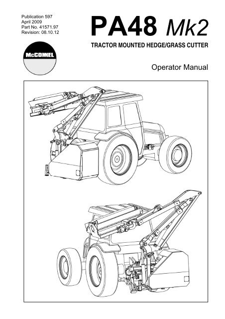
Publication 597April 2009Part No. 41571.97Revision: 08.10.12<strong>PA48</strong> <strong>Mk2</strong>TRACTOR MOUNTED HEDGE/GRASS CUTTER<strong>Operator</strong> <strong>Manual</strong>
IMPORTANTVERIFICATION OF WARRANTY REGISTRATIONDEALER WARRANTY INFORMATION & REGISTRATION VERIFICATIONIt is imperative that the selling dealer registers this machine with <strong>McConnel</strong> Limited beforedelivery to the end user – failure to do so may affect the validity of the machine warranty.To register machines go to the <strong>McConnel</strong> Limited web site at www.mcconnel.com, logonto ‘Dealer Inside’ and select the ‘Machine Registration button’ which can be found inthe Service Section of the site. Confirm to the customer that the machine has beenregistered in the section below.Should you experience any problems registering a machine in this manner please contactthe <strong>McConnel</strong> Service Department on 01584 875848.Registration VerificationDealer Name: ……………………..…………………………………………………………….Dealer Address: …….………………………………………………………………………….Customer Name: ……………………..…………………………………………………………Date of Warranty Registration: ……/……/...…… Dealer Signature: ………………..……NOTE TO CUSTOMER / OWNERPlease ensure that the above section above has been completed and signed by the sellingdealer to verify that your machine has been registered with <strong>McConnel</strong> Limited.IMPORTANT: During the initial ‘bedding in’ period of a new machine it is the customer’s responsibilityto regularly inspect all nuts, bolts and hose connections for tightness and re-tighten if required. Newhydraulic connections occasionally weep small amounts of oil as the seals and joints settle in – wherethis occurs it can be cured by re-tightening the connection – refer to torque settings chart below. Thetasks stated above should be performed on an hourly basis during the first day of work and at leastdaily thereafter as part of the machines general maintenance procedure.TORQUE SETTINGS FOR HYDRAULIC FITTINGSHYDRAULIC HOSE ENDSPORT ADAPTORS WITH BONDED SEALSBSP Setting Metric BSP Setting Metric1/4” 18 Nm 19 mm 1/4” 34 Nm 19 mm3/8” 31 Nm 22 mm 3/8” 47 Nm 22 mm1/2” 49 Nm 27 mm 1/2” 102 Nm 27 mm5/8” 60 Nm 30 mm 5/8” 122 Nm 30 mm3/4” 80 Nm 32 mm 3/4” 149 Nm 32 mm1” 125 Nm 41 mm 1” 203 Nm 41 mm1.1/4” 190 Nm 50 mm 1.1/4” 305 Nm 50 mm1.1/2” 250 Nm 55 mm 1.1/2” 305 Nm 55 mm2” 420 Nm 70 mm 2” 400 Nm 70 mm
WARRANTY POLICYWARRANTY REGISTRATIONAll machines must be registered, by the selling dealer with <strong>McConnel</strong> Ltd, before delivery to the enduser. On receipt of the goods it is the buyer’s responsibility to check that the Verification of WarrantyRegistration in the <strong>Operator</strong>’s <strong>Manual</strong> has been completed by the selling dealer.1. LIMITED WARRANTIES1.01. All machines supplied by <strong>McConnel</strong> Limited are warranted to be free from defects in materialand workmanship from the date of sale to the original purchaser for a period of 12 months,unless a different period is specified.1.02. All spare parts supplied by <strong>McConnel</strong> Limited are warranted to be free from defects in materialand workmanship from the date of sale to the original purchaser for a period of 6 months.1.03. The manufacturer will replace or repair for the purchaser any part or parts found, uponexamination at its factory, to be defective under normal use and service due to defects inmaterial or workmanship. Returned parts must be complete and unexamined.1.04. This warranty does not apply to any part of the goods, which has been subjected to improper orabnormal use, negligence, alteration, modification, fitment of non-genuine parts, accidentdamage, or damage resulting from contact with overhead power lines, damage caused byforeign objects (e.g. stones, iron, material other than vegetation), failure due to lack ofmaintenance, use of incorrect oil or lubricants, contamination of the oil, or which has served itsnormal life. This warranty does not apply to any expendable items such as blades, flails, flapkits, skids, soil engaging parts, shields, guards, wear pads or pneumatic tyres.1.05. Temporary repairs and consequential loss - i.e. oil, downtime and associated parts arespecifically excluded from the warranty.1.06. Warranty on hoses is limited to 12 months and does not include hoses which have sufferedexternal damage. Only complete hoses may be returned under warranty, any which have beencut or repaired will be rejected.1.07. Machines must be repaired immediately a problem arises. Continued use of the machine after aproblem has occurred can result in further component failures, for which <strong>McConnel</strong> Ltd cannotbe held liable, and may have safety implications.1.08. Except as provided herein, no employee, agent, dealer or other person is authorised to give anywarranties of any nature on behalf of <strong>McConnel</strong> Ltd.1.09. For machine warranty periods in excess of 12 months the following additional exclusions shallapply:1) Hoses, external seals, exposed pipes and hydraulic tank breathers.2) Filters.3) Rubber mountings.4) External electric wiring.1.10. All service work, particularly filter changes, must be carried out in accordance with themanufacturer’s service schedule. Failure to comply will invalidate the warranty. In the event of aclaim, proof of the service work being carried out may be required.NB Warranty cover will be invalid if any non-genuine parts have been fitted or used. Use ofnon-genuine parts may seriously affect the machine’s performance and safety. <strong>McConnel</strong> Ltdcannot be held responsible for any failures or safety implications that arise due to the use ofnon-genuine parts.
2. REMEDIES AND PROCEDURES2.01. The warranty is not effective unless the Selling Dealer registers the machine, via the <strong>McConnel</strong>web site and confirms the registration to the purchaser by completing the confirmation form inthe operator’s manual.2.02. Any fault must be reported to an authorised <strong>McConnel</strong> dealer as soon as it occurs. Continueduse of a machine, after a fault has occurred, can result in further component failure for which<strong>McConnel</strong> Ltd cannot be held liable.2.03. Repairs should be undertaken within two days of the failure. Claims submitted for repairsundertaken more than 2 weeks after a failure has occurred, or 2 days after the parts weresupplied will be rejected, unless the delay has been authorised by <strong>McConnel</strong> Ltd.2.04. All claims must be submitted, by an authorised <strong>McConnel</strong> Service Dealer, within 30 days of thedate of repair.2.05. Following examination of the claim and parts the manufacture will pay, at their discretion, forany valid claim the cost of any parts and an appropriate labour allowance if applicable.2.06. The submission of a claim is not a guarantee of payment.2.07. Any decision reached by <strong>McConnel</strong> Ltd. is final.3. LIMITATION OF LIABILITY3.01. The manufacturer disclaims any express (except as set forth herein) and implied warrantieswith respect to the goods including, but not limited to, merchantability and fitness for a particularpurpose.3.02. The manufacturer makes no warranty as to the design, capability, capacity or suitability for useof the goods.3.03. Except as provided herein, the manufacturer shall have no liability or responsibility to thepurchaser or any other person or entity with respect to any liability, loss, or damage caused oralleged to be caused directly or indirectly by the goods including, but not limited to, any indirect,special, consequential, or incidental damages resulting from the use or operation of the goodsor any breach of this warranty. Notwithstanding the above limitations and warranties, themanufacturer’s liability hereunder for damages incurred by the purchaser or others shall notexceed the price of the goods.3.04. No action arising out of any claimed breach of this warranty or transactions under this warrantymay be brought more than one (1) year after the cause of the action has occurred.4. MISCELLANEOUS4.01. The manufacturer may waive compliance with any of the terms of this limited warranty, but nowaiver of any terms shall be deemed to be a waiver of any other term.4.02. If any provision of this limited warranty shall violate any applicable law and is held to beunenforceable, then the invalidity of such provision shall not invalidate any other provisionsherein.4.03. Applicable law may provide rights and benefits to the purchaser in addition to those providedherein.
DECLARATION OF CONFORMITYConforming to EU Machinery Directive 2006/42/ECWe,McCONNEL LIMITED, Temeside Works, Ludlow, Shropshire SY8 1JL, UKHereby declare that:The Product; Tractor Mounted Hedgecutter / Grass MowerProduct Code; <strong>PA48</strong>Serial No. & Date ………………………………… Type …………………………Manufactured in; United KingdomComplies with the required provisions of the Machinery Directive 2006/42/ECThe machinery directive is supported by the following harmonized standards; BS EN ISO 14121-1 (2007) Safety of machinery - Risk assessment, Part 1:Principles Part 2: practical guide and examples of methods. BS EN ISO 12100-1 (2010) Safety of machinery - Part 1: Basic terminology andmethodology Part 2: Technical principles. BS EN 349(1993)+ A1 (2008) Safety of machinery - Minimum distances to avoid theentrapment with human body parts. BS EN 953 (1998) Safety of machinery - Guards General requirements for thedesign and construction of fixed and movable guards. BS EN 982(1996)+ A1 (2008) Safety requirements for fluid power systems and theircomponents. HydraulicsMcCONNEL LIMITED operates an ISO 9001:2008 quality management system,certificate number: FM25970.This system is continually assessed by the;British Standards Institution (BSI), Beech House, Milton Keynes, MK14 6ES, UKBSI is accredited by UK Accreditation Service, accreditation number: UKAS 003.The EC declaration only applies if the machine stated above is used inaccordance with the operating instructions.Signed …………………................ Responsible PersonCHRISTIAN DAVIES on behalf of McCONNEL LIMITEDStatus: General Manager Date: May 2011
POWER ARM INSPECTION AND MAINTENANCEA daily equipment inspection of the tractor and mower should be conducted before theequipment is used. You may use the inspection sheets to assist with these dailyinspections. Any damaged or missing guards should be repaired or replaced beforeoperating the mower. Failure to repair the damaged shield can result in objects beingthrown from the mower and possibly hitting the operator or bystander.Inspect the Mower for Safe Operating ConditionMake sure the driveline guards and shielding are in place and in good repair. Inspect the flexible thrown object shielding to assure that they are in place on thefront and rear of the mower head and in good repair. Repair or replace anydamaged or missing thrown object shields. Ensure the mower cutting height is set high enough to reduce the possibility of themower blades contacting the ground. Actual height will be dependent on the groundconditions. Increase the height when working in rough or undulating conditions. Inspect for broken, chipped, bent, missing, or severely worn blades. Replacedamaged blades before operating the mower. Ensure the blade retaining bolts andfasteners are secure and tight. Ensure all head bolts and nuts are tight. Lubricate the driveline universal joints and telescoping members daily. Grease the rotor and roller bearings and inspect their condition. Inspect for any oil leaks or damaged hoses Inspect for worn or damaged decals and safety instructions. Replace unreadable,damaged or missing safety decals. Follow the operator’s manual(s) inspection and maintenance instructions forlubricating parts, and keeping thrown object shielding, driveline guards, rotatingparts shields, mower blades and decals in good repair.Inspect the Tractor for Safe Operating Condition: Inspect the controls, lights, SMVs (Slow Moving Vehicle sign), seat belts, andROPS to assure that they are in place and in good working order. Be sure the tires, wheels, lug bolts/nuts are in good condition. Make sure the tractor brakes and steering are in proper operating condition. Follow the operator’s manual(s) inspection and maintenance procedures forkeeping the tractor in good and safe condition before operating.The inspection sheet on the following page should be kept in this book as a record. Asecond sheet is included for you to cut out and photocopy or the inspection sheets can bedownloaded from our website at;http://www.mcconnel.com/support/aftersales/default.aspx?nav=After Sales
POWER ARM PRE-OPERATION InspectionPower Arm ID ________________ Date: _______________ Shift: _______________WARNINGBefore conducting the inspection, make sure the tractor engine is off, the key removed, allrotation has stopped and the tractor is in park with the parking brake engaged. Make surethe mower head is resting on the ground or is securely blocked up and supported and allhydraulic pressure has been relieved.ItemThe <strong>Operator</strong>’s <strong>Manual</strong> is in the Canister on the mowerAll Warning Decals are in place, clean and legibleAll Lights are clean and workingThe Mounting frame bolts are in place and tightThe Arm pivot pins are tight and correctly securedThere are no cracks in the armsThe Hyd. Cylinder pins are tight and correctly securedThe Hyd Cylinder hose connections are tightThe Hyd. Pump hose connections are tightThe Hyd. Valve hose connections are tightThe Hyd. Valve controls function properlyThere are no damaged hosesThe Oil level is to the green mark on the tank sight glassThere is no evidence of Hydraulic oil leaksFlails are not missing, chipped, broken or excessively wornThe Flail bolts are tightThe Front & Rear Flaps are fittrd and in good conditionThe Front hood is in place and in good conditionThe Wire Trap is in good conditionThe Skid shoes are in good condition & tightThere are no cracks or holes in flail casingThe Hyd. motor mounting bolts are tightAll Flail Head Nuts and Bolts are tightThe Rotor Bearings are in good condition and greasedThe Roller bearings are in good condition and greasedThe drive line Shaft guard is in good conditionThe drive line shaft guard is correctly securedControls are securely mounted in the cabWith engine running check arm operationHave a spare pack of flails, bushes, bolts and nutsCondition atstart of shiftSpecific Comments if not O.K.<strong>Operator</strong>s Signature: ___________________________________________DO NOT OPERATE an UNSAFE TRACTOR or MOWER
TRACTOR PRE-OPERATION InspectionPower Arm ID ________________ Date: _______________ Shift: _______________WARNING Before conducting the inspection, make sure the tractor engine is off, the key is removedall rotation has stopped and the tractor is in park with the parking brake engaged. Anyimplement attached to the tractor is firmly on the ground.ItemThe flashing lights function properly.All lights are clean and working correctlyAll cab windows are clean and wipers working correctlyThe SMV sign, where required, is clean and visible.The tyres are in good condition with correct pressure.The wheel nuts are tight.The tractor brakes are in good condition.The steering linkage is in good condition.There are no visible oil leaks.The hydraulic controls function properly.The ROPS or ROPS cab is in good condition.The seatbelt is in place and in good condition.The 3-point hitch is in good condition.The drawbar/pick up hook is secure & in good conditionThe PTO master shield is in place.The engine oil level is full.The brake fluid level is full.The power steering fluid level is full.The fuel level is adequate.The engine coolant fluid level is full.The radiator & oil cooler are free of debris.The air filter is in good conditionCondition atstart of shiftSpecific Comments if not O.K.<strong>Operator</strong>s Signature: ___________________________________________DO NOT OPERATE an UNSAFE TRACTOR or MOWER
GENERAL INFORMATIONAlways read this manual before fitting or operating the machine – whenever any doubtexists contact your dealer or the <strong>McConnel</strong> Service Department for advice and assistance.Use only <strong>McConnel</strong> Genuine Service Parts on <strong>McConnel</strong> Equipment and MachinesDEFINITIONS – The following definitions apply throughout this manual:WARNINGAn operating procedure, technique etc., which –can result in personal injury or loss of life if not observed carefully.CAUTIONAn operating procedure, technique etc., which –can result in damage to either machine or equipment if not observed carefully.NOTEAn operating procedure, technique etc., which –is considered essential to emphasis.LEFT AND RIGHT HANDThis term is applicable to the machine when attached to the tractor and is viewedfrom the rear – this also applies to tractor references.MACHINE & DEALER INFORMATIONRecord the Serial Number of your machine on this page and always quote this number whenordering parts. Whenever information concerning the machine is requested remember also to statethe make and model of tractor to which the machine is fitted.Machine Serial Number:Machine Model details:Dealer Name:Dealer Address:Dealer Telephone No:Dealer Email Address:Installation Date:1
INTRODUCTION – Model Specifications<strong>PA48</strong> Series (All Models)Linkage mounted.Right or left hand cutting.1.2M heavy duty flailhead (Hedge or Grass).Spring assisted gravity breakaway.<strong>Operator</strong> guard.180 litre hydraulic reservoir.<strong>PA48</strong> SI ModelsSemi independent hydraulicsCable controls.Rotor engagement by tractor's PTO lever.54HP hydraulic system.<strong>PA48</strong> TI ModelsTotally independent hydraulics powered by tandem PTO pump.Cable controls.Independent reversible rotor on/off valve.54HP hydraulic system.<strong>PA48</strong>E TI ModelsTotally independent hydraulics powered by tandem PTO pump.Electric controls - solenoid operated.Choice of control units - Switchbox, Monolever or ProportionalIndependent reversible rotor on/off valve.54HP hydraulic system.2
This machine has the potential to be extremely dangerous, in the wrong hands it can kill ormaim. It is therefore imperative that both owner, and operator of this machine, read andunderstand the following section to ensure that they are fully aware of the dangers that do,or may exist, and their responsibilities surrounding the use and operation of the machine.The operator of this machine is responsible not only for their own safety but equally for thesafety of others who may come into the close proximity of the machine, as the owner youare responsible for both.When the machine is not in use the cutting head should be lowered to rest on the ground.In the event of a fault being detected with the machine’s operation it should be stoppedimmediately and not used again until the fault has been corrected by a qualified technician.POTENTIAL SIGNIFICANT DANGERS ASSOCIATED WITH THE USE OF THIS MACHINE:▲ Being hit by debris thrown by rotating components.▲ Being hit by machine parts ejected through damage during use.▲ Being caught on a rotating power take-off (PTO) shaft.▲ Being caught in other moving parts i.e.: belts, pulleys and cutting heads.▲ Electrocution from Overhead Power Lines (by contact with or ‘flashover’ from).▲ Being hit by cutting heads or machine arms as they move.▲ Becoming trapped between tractor and machine when hitching or unhitching.▲ Tractor overbalancing when machine arm is extended.▲ Injection of high-pressure oil from hydraulic hoses or couplings.▲ Machine overbalancing when freestanding (out of use).▲ Road traffic accidents due to collision or debris on the road.3
BEFORE USING THIS MACHINE YOU MUST:▲ Ensure you read all sections of the operator handbook.▲ Ensure the operator is, or has been, properly trained to use the machine.▲ Ensure the operator has been issued with and reads the operator handbook.▲ Ensure the operator understands and follows the instructions in operator handbook.▲ Ensure the tractor front, rear and side(s) are fitted with metal mesh or polycarbonateguards of suitable size and strength to protect the operator against thrown debris orparts.▲ Ensure tractor guards are fitted correctly, are undamaged and kept properlymaintained.▲ Ensure that all machine guards are in position, are undamaged, and are keptmaintained in accordance with the manufacturer’s recommendations.▲ Ensure flails and their fixings are of a type recommended by the manufacturer, aresecurely attached and that none are missing or damaged.▲ Ensure hydraulic pipes are carefully and correctly routed to avoid damage by chaffing,stretching or pinching and that they are held in place with the correct fittings.▲ Always follow the manufacturer’s instructions for attachment and removal of themachine from the tractor.▲ Check that the machine fittings and couplings are in good condition.▲ Ensure the tractor meets the minimum weight recommendations of the machine’smanufacturer and that ballast is used as necessary.▲ Always inspect the work area thoroughly before starting to note obstacles and removewire, bottles, cans and other debris.▲ Use clear suitably sized warning signs to alert others to the nature of the machineworking within that area. Signs should be placed at both ends of the work site. (It isrecommended that signs used are of a size and type specified by the Department ofTransport and positioned in accordance with their, and the Local Highways Authority,guidelines).▲ Ensure the operator is protected from noise. Ear defenders should be worn and tractorcab doors and windows must be kept closed. Machine controls should be routedthrough proprietary openings in the cab to enable all windows to be shut fully.▲ Always work at a safe speed taking account of the conditions i.e.: terrain, highwayproximity and obstacles around and above the machine. Extra special attention shouldbe applied to Overhead Power Lines. Some of our machines are capable of reach inexcess of 8 metres (26 feet) this means they have the potential to well exceed, bypossibly 3 metres (9’ 9”), the lowest legal minimum height of 5.2 metres from theground for 11,000 and 33,000 volt power lines. It cannot be stressed enough thedangers that surround this capability, it is therefore vital that the operator is fully awareof the maximum height and reach of the machine, and that they are fully conversantwith all aspects regarding the safe minimum distances that apply when working withmachines in close proximity to Power Lines. (Further information on this subject can beobtained from the Health & Safety Executive or your Local Power Company).4
▲ Always disengage the machine, kill the tractor engine, remove and pocket the keybefore dismounting for any reason.▲ Always clear up all debris left at the work area, it may cause hazard to others.▲ Always ensure when you remove your machine from the tractor that it is left in a safeand stable position using the stands and props provided and secured if necessary.WHEN NOT TO USE THIS MACHINE:▲ Never attempt to use this machine if you have not been trained to do so.▲ Never use a machine until you have read and understood the operator handbook, arefamiliar with it, and practiced the controls.▲ Never use a machine that is poorly maintained.▲ Never use a machine if guards are missing or damaged.▲ Never use a machine on which the hydraulic system shows signs of wear or damage.▲ Never fit, or use, a machine on a tractor that does not meet the manufacturer’sminimum specification level.▲ Never use a machine fitted to a tractor that does not have suitable front, rear andside(s) cab guarding made of metal mesh or polycarbonate.▲ Never use the machine if the tractor cab guarding is damaged, deteriorating or badlyfitted.▲ Never turn a machine cutting head to an angle that causes debris to be ejectedtowards the cab.▲ Never start or continue to work a machine if people are nearby or approaching - Stopand wait until they are at a safe distance before continuing. WARNING: Some CuttingHeads may continue to ‘freewheel’ for up to 40 seconds after being stopped.▲ Never attempt to use a machine on materials in excess of its capability.▲ Never use a machine to perform a task it has not been designed to do.▲ Never operate the tractor or machine controls from any position other than from thedriving seat, especially whilst hitching or unhitching the machine.▲ Never carry out maintenance of a machine or a tractor whilst the engine is running –the engine should be switched off, the key removed and pocketed.▲ Never leave a machine unattended in a raised position – it should be lowered to theground in a safe position on a level firm site.▲ Never leave a tractor with the key in or the engine running.▲ Never carry out maintenance on any part or component of a machine that is raisedunless that part or component has been properly substantially braced or supported.▲ Never attempt to detect a hydraulic leak with your hand – use a piece of cardboard.▲ Never allow children near to, or play on, a tractor or machine under any circumstances.5
TRACTOR REQUIREMENTSTractor Weight (Including ballast weight if necessary)Minimum 3000kgHP RequirementMinimum 60HPTractor Linkage RequirementCategory 2PTO ShaftTractor must be equipped with a live drive PTO to enable continuous flailhead operationwhen forward motion of the tractor is stopped.Check Chains / StabilizersCheck chains or stabilizers must be fitted and tightened.Linkage IsolationA linkage isolation facility is necessary for SI models only.Tractor Relief ValveFor Si models only tractor relief valve must be set above 2000 psi (140bar).Tractor Hydraulic Flow RateHydraulic flow rates are not crucial for SI modelsFront Mounted ModelsBefore fitting a front mounted machine to your tractor seek the advice of the tractormanufacturer or your local dealer regarding its suitability and all information in relation toadditional linkage, ballast or weight requirements that may be required.CAUTIONNever attach a machine to a tractor that is unsuitable or poorly maintained –where doubt exists always seek the advice of the tractor manufacturer or yourlocal dealer before attempting to fit the machine.7
VEHICLE / TRACTOR PREPARATIONWe recommend vehicles are fitted with cabsusing ‘safety glass’ windows and protectiveguarding when used with our machines.Fit <strong>Operator</strong> Guard (Part No. 7313324) usingthe hooks provided. Shape the mesh to coverall vulnerable areas. The driver must belooking through mesh and/or polycarbonateglazing when viewing the flail head in anyworking position - unless the vehicle/ cab manufacturer can demonstrate that thepenetration resistance is equivalent to, or higher than, that provided bymesh/polycarbonate glazing. If the tractor has a roll bar only, a frame must be made tocarry both mesh and polycarbonate glazing. The operator should also use personalprotective equipment to reduce the risk of serious injury such as; eye protection (meshvisor to EN1731 or safety glasses to EN166), hearing protection to EN352, safety helmetto EN297, gloves, filter mask and high visibility clothing.Vehicle Ballast: It is imperative when attaching ‘third-party’ equipment to a vehicle thatthe maximum possible stability of the machine and vehicle combination is achieved – thiscan be accomplished by the utilization of ‘ballast’ in order to counter-balance the additionalequipment added. Front weights may be required for rear mounted machines to place15% of total outfit weight on the front axle for stable transport on the road and to reduce‘crabbing’ due to the drag of the cutting unit when working on the ground.Rear weights may be required to maintain a reasonable amount of rear axle load on theopposite wheel from the arms when in work; for normal off-ground work i.e. hedge cuttingthis should be 20% of rear axle weight or more for adequate control, and for ground worki.e. verge mowing with experienced operators, this can be reduced to 10%.All factors must be addressed in order to match the type and nature of the equipmentadded to the circumstances under which it will be used – in the instance of Power ArmHedgecutters it must be remembered that the machines centre of gravity during work willbe constantly moving and will differ from that during transport mode, therefore balancebecomes critical.Factors that effect stability:• Centre of gravity of the tractor/machine combination.• Geometric conditions, e.g. position of the cutting head and ballast.• Weight, track width and wheelbase of the tractor.• Acceleration, braking, turning and the relative position of the cutting head during theseoperations.• Ground conditions, e.g. slope, grip, load capability of the soil/surface.• Rigidity of implement mounting.Suggestions to increase stability:• Increasing rear wheel track; a vehicle with a wider wheel track is more stable.• Ballasting the wheel; it is preferable to use external weights but liquid can be added to around75% of the tyre volume – water with anti-freeze or the heavier Calcium Chloride alternative canbe used.• Addition of weights – care should be taken in selecting the location of the weights to ensurethey are added to a position that offers the greatest advantage.• Front axle locking (check with tractor manufacturer).NOTE: The advice above is offered as a guide for stability only and is not a guide to vehicle strength.It is recommended that you consult your vehicle manufacturer or local dealer to obtain specificadvice on this subject, additionally advice should be sought from a tyre specialist with regard to tyrepressures and ratings suitable for the type and nature of the machine you intend to fit.8
CLOSED CENTRE CONVERSION KIT – Semi-Independent Models onlyControl Valve Conversion Kit (Part No. 8130059)This consists of a relief valve-blanking plug, which should be installed in place of theexisting relief valve, and a pressure gallery blanking plug, which is installed in place of thestandard blanking plug at the valve outlet end next to the lift ram gland connection.NOTE: Take care when extracting the relief valve not to damage the copper sealingwasher, as it is to be re-used.When working in this mode the tractor's pressure control valve must not exceed 2500 P.S.I(170 Bar).9
DELIVERY & PRE-ATTACHMENT (Dealer Reference)DeliveryThe machine will be delivered in a partially dismantled condition secured with transportstraps and banding. Select a firm level site on which to place the machine before removingthe straps, banding and other loose items.Handling the MachineHandling of the machine should always be performed using suitable overhead liftingequipment with a minimum safe lifting capacity over and above the maximum weight of themachine. Always ensure the machine is balanced during the lifting procedure and that allbystanders are kept well clear of the raised machine.Post Delivery AssemblyIn allow for a compact shipping state the machine will be delivered with the tension linkdisconnected from the rocker and the stand legs retracted – these items will need to becorrectly installed before initial attachment to a tractor.The procedure is as follows:Stand LegsRaise the machine using suitableoverhead lifting equipment.Lower stand legs and secure inposition using pins and locking pins –the hole position selected should beat a height that places the gearboxstub axle approximately 75mm (3”)below the height of the tractor’s PTOshaft when the machine is at rest onthe ground. Note the hole positionused and ensure the equivalent oneis used on both sides of the machine.Tension Link AttachmentRequest assistance for this task- Operate ‘lift up’ on machinecontrols sufficient only for dipperarm to clear the ground.Pivot out the dipper arm until thetension link can be connectedand secure in position with pinand fixings supplied.10
HYDRAULIC OILHydraulic Oil ReservoirFill the tank with oil selected from the chartbelow or a good quality equivalent to a pointwhere the level is between the minimum andmaximum marks on the tank gauge. Whenthe machine is initially run the level will dropas the oil is drawn into the circuit - top backup as required to the correct l evel on thegauge.Always use clean receptacles when handlingand transferring oil to avoid moisture or dirtcontamination that can damage componentsand/or reduce machine performance.NOTE: Refer to the maintenance section for further information on the subject of hydraulicoil and system filtration.Reservoir CapacityThe oil tank capacity of the machine is approximately 180 Litre.Recommended Hydraulic OilsFor initial filling of the oil reservoir, periodic oil changes and replenishment purposes thefollowing hydraulic oils, or a good quality equivalent, are recommended;NOTE: Only use oils that are ISO 18/16/13, NAS7, or cleaner.Manufacturer Cold or Temperate Climate Hot ClimateBP Bartran 46Energol HLP-HM 46Bartran 68Energol HLP-HM 68CASTROL Hyspin AWH-M 46 Hyspin AWH-M 68COMMA Hydraulic Oil LIC 15 Hydraulic Oil LIC 20ELF Hydrelf HV 46Hydrelf HV 68Hydrelf XV 46ESSO Univis N 46 Univis N 68FUCHS(UK/Non UK markets*)Renolin 46Renolin HVZ 46Renolin CL46/B15*Renolin AF46/ZAF46B*Renolin 68Renolin HVZ 68Renolin CL68/B20*Renolin AF68/ZAF68B*GREENWAY Excelpower HY 68 Excelpower HY 68MILLERS Millmax 46Millmax HV 46MORRIS Liquimatic 5Liquimatic HV 46Triad 46SHELL Tellus 46Tellus T46TEXACO Rando HD 46Rando HDZ 46Millmax 68Millmax HV 68Liquimatic 6Liquimatic HV 68Triad 68Tellus 68Tellus T68Rando HD 68Rando HDZ 68TOTAL Equivis ZS 46 Equivis ZS 6811
ATTACHMENT TO TRACTORAttachment of the machine to the tractor should always be performed on a firmlevel site.* For electric controlled models only the base end pin of the angling ram and the rodend pins of the lift and reach rams must be removed.* On SI models only reverse the tractor up as closely as possible. Fit suitable returnconnection to the tractor and connect the return hose before connecting the supply hose tothe tractors external services point with a suitable self-seal coupling.* Ensure that lift ram tap is fully open.* With the aid of a crowbar prise the flail head sideways to allow the tractor to be reversedupFor cable controlled models only assistance will be needed to simultaneously select‘Reach Out’ and ‘Angle Down’ to allow the oil to flow whilst the arms are being moved.WARNING!As a safety precaution to prevent the possibility of the flail head slipping sideways and thearm collapsing on the fitter as he is prying the head sideways, a loop of strong rope or wire,with sufficient slack to allow the required flail head movement should connect the frameand dipper - this will then act as an arrestor in the event of this happening. Leave inposition until attachment is complete.Adjust tractor drop arms to enable the draft links to lower to within 15” (375mm) of theground.Remove the top link and machine yoke completely.Reverse the tractor squarely to the front of the machine, engage draft link pins and secure.Attach yoke to the top hitch position on the tractor ensuring the lug for the top link isuppermost.Unlimber the machine controls and fit into the tractor cab – refer to control fitment pages..Install the top link between yoke and upper hitch position on the machine (If necessaryfitting Cat.1 sleeves into the ball ends of the top link).* Raise the machine on its three point linkage until the PTO shaft and the gearbox stubshaft are as near as possible in a straight line.* At this point check that the welded in pins between the jaws of the yoke are tightlyagainst the top of the mounting rail - If the welded in pins are not in contact with the rail themachine must be lowered to the ground, the next hole on the yoke top link lug selected,the machine raised again and contact checked. Repeat again in the third hole if necessary.On subsequent fitment to the same tractor the hole selected is always used.Secure the yoke with the locking pins and spring cotters provided ensuring that theyengage in matching holes in the mounting rails.Lower the quadrant lever so that the machines weight is taken by the yoke - Adjust the toplink to bring the pillar upright.12
* Reposition the eccentric collars in the holes immediately behind the yoke and adjust untilboth collars abut against the face of the yoke plates. Tighten in position. These collars actas stops for the yoke during subsequent fitting to the same tractor.lf the tractor used ischanged new collar positions will need to be worked out following the previous procedure.WARNING!The quadrant lever or machine controls must be operated from the tractor seat. During thisoperation ensure no one is standing on or amongst the linkage arms or bars.* Measure the PTO drive shaft length – refer to PTO driveshaft installation page for details.Fit PTO shaft in position ensuring the collar locking devices on the shaft are fully engaged.Attach torque chains to convenient points to prevent the guards from rotating with theshaft.Check that the rotor control valve is in the stop position (TI models only).* For electric controlled machines only engage the PTO (see page 18) and select ‘Liftdown’ until the lift ramrod together with its pin can be re-assembled in position. Simïlarlyselecting ‘Reach out’ and ‘Angle down’ will enable the respective ram rods and pins to bereplaced.Carry out final adjustment of the tractor lift arm-leveling box to bring the main framehorizontal. This should be checked with the arms at approximately half reach with the flailhead clear of the ground.* Remove the rope arrestor loop.Carry out final adjustment of the tractor lift arm-leveling box to bring the main framehorizontal. This should be checked with the arms at approximately half reach with theflail head clear of the ground.Raise the parking legs and secure in position.13
Raise the parking legs and secure in position.Carefully operate the machine through its full range of movement whilst checking that thehoses are not strained, pinched, chaffed or kinked and that all movements arefunctioning correctly.* Assemble the cover plate and the hedge hood into positionFold the machine into the transport position (refer to page 48).The machine is now ready to procede to the work site.The procedure stated above is for initial attachment of the machine only, for subsequentattachment of the machine to the same tractor paragraphs marked * no longer apply.EMERGENCY STOPPINGIn all emergency situations machine operation and functions must be stopped immediately;Stop PTO operation using the tractor controls then immediately kill electrical power to themachine using the Off (Emergency Stop) switch on the machine’s control unit.WARNING: Auto-Reset MachinesWhen the Auto-Reset feature is active the machines arm set is capable ofunintentional movement even when the PTO is switched off and stationary.Always ensure that electrical power to the machine is switched off using theOff (Emergency Stop) switch on the machine’s control unit in emergencysituations and/or when the machine is not being operated.WARNING: Cable Operated MachinesIn certain conditions, and/or if the Auto-Reset feature is active, the arm setson cable operated machines possess the potential to move unintentionally,even when the PTO is switched off and stationary, if the levers were to beaccidentally operated. Care must be adopted to avoid any movement of thelevers when the machine is not being operated. Ensure arm sets are loweredfully to the ground when the machine is parked up or not in use.14
PTO DRIVESHAFT INSTALLATIONThe PTO driveshaft attaches between the tractor and the machine gearbox to transfer thepower required to the run and operate the machine – it is important to achieve the correctshaft length to avoid risk of it ‘bottoming out’ when raising or lowering the machine.The procedure for measuring andcutting the shaft is as follows:Measuring the PTO ShaftWith the machine attached to thetractor in the working position measurethe horizontal distance ‘A’ from thetractor’s PTO to the input shaft on themachines gearbox and subtract 75mm(3”) – this figure is the required shaftlength.Place the fully closed PTO shaft onthe ground and measure its overalllength, if the shaft is shorter than therequired length you can use it withoutthe need to shorten - providing itallows for a minimum 150mm (6”)overlap when fitted.If the shaft is longer subtract therequired shaft length plus an additional75mm (3”) - the resulting figure is theexcess length that will need to beremoved from each half of the shaft.Cutting the PTO ShaftSeparate the two halves and using themeasurement obtained above shortenboth the plastic guarding and the innersteel profile tubes of each shaft by thissame amount. De-burr the cut tubeswith a file to remove rough or sharpedges and thoroughly clean to removeswarf before greasing, assembling and fitting the shaft.NOTE: For subsequent use with different tractors the shaft should be measured again tocheck suitability – there must be a minimum shaft overlap of 150mm (6”).MaintenanceTo increase the working life of the PTO shaft it should be periodically checked, cleanedand lubricated – refer to the PTO maintenance section for further details on this subject.16
FITTING OPERATOR CONTROL UNITSFitment of the operator controls in the tractor cab will vary depending on the particularmodel or specification of machine – the information below lists the differing methods offitment for the various types of controls available.Cable ControlsCable control units are provided with, and attached to, a mounting bracket – the bracketshould be securely fixed to the internal mud wing or cab cladding in a suitable convenientlocation that offers ease of use without interfering with normal tractor operation.In deciding the final position of the control unit bear in mind the location of the cable run –make sure the minimum acceptable cable bend radii of 8” (200mm) is not exceeded.Ensure during fitting that no structural member of the tractor cab or roll bar is drilled ordamaged.The cable rotor control valve lever on cable controlled machines will be assembled as acomponent part of the main bank of controls and therefore shares the same mountingbracket.On electric machines with cable operated rotor control valve the lever will be supplied as a‘standalone’ unit with its own individual mounting bracket – this should be fitted in thesame manner as above adopting the same precautions pertaining to attachment and cableruns.Electric ControlsDepending on the particular type of control, electric units are supplied either with amounting bracket or a mounting pillar which should be bolted to the internal mud wing orcab cladding in a suitable convenient location that offers ease of use without interferingwith normal tractor operation. Mounting pillars can be bent or twisted to achieve acomfortable working position.Ensure during fitting that no structural member of the tractor cab or roll bar is drilled ordamaged.The power supply cable should be connected directly to the tractors battery - do not usecigarette lighter type connections as these prove to be sporadic and unreliable for controlapplications. Control units are 12 volt D.C. operated; the brown lead is positive (+) and theblue lead is negative (-).17
RUNNING UP PROCEDURECAUTION! Before initial use of a new machine, all lubrication points must begreased and the gearbox and oil tank levels checked and where required toppedup before attempting to use the machine. See maintenance section for details.TI Models onlyEnsure that the rotor control valve is in the ‘Stop’ position, start tractor and engage PTO toallow oil to circulate through the return line filter for about 5 minutes without operation ofthe armhead control lever.Operate the armhead levers through their complete range ensuring that all movements arefunctioning correctly.Place the flail head at a safe attitude and move the rotor control to ‘Start’ position. Afterinitial fluctuation the rotor should settle to a steady speed. Increase PTO speed toapproximately 360rpm and run for a further five minutes before disengaging and stoppingthe tractor.Check the hose runs and observe that they are free from any pinching, chafing straining orkinks. Re-check the oil level in the tank and top up if required.SI Models onlyEnsure PTO lever is in neutral position, and isolate tractor hydraulic linkage. Start tractorand select external service supply. Allow the tractor to run for several minutes beforeattempting to operate any of the machine control levers.On operating move the levers through their complete range ensuring that all movementsare functioning correctly.Check the tractor rear axle oil level and top up if necessary.Place the flail head at a safe attitude and bring tractor engine revolutions to 1000rpm,engage PTO and allow the rotor to run for several minutes. Do not leave the tractor cab orallow anyone to approach the flail head at this time.CAUTION!Do not allow the pump to continue working if the rotor does not turn –overheating and serious damage to the pump can occur in a very short time.After running up the machine, increase PTO speed to approximately 360rpm and run for afurther five minutes to allow the oil to circulate through the return line filter beforedisengaging the PTO and stopping the tractor.Check the hose runs and observe that they are free from any pinching, chafing, strainingor kinks. Re-check the oil level in the tank and top up as necessary.All ModelsReplace return filter elements after an initial 12 hours of operation and every 500 hoursthereafter.18
REMOVAL FROM TRACTORDANGER!READ CAREFULLY BEFORE COMMENCING TO REMOVE THE MACHINEFROM THE TRACTORTHE ORDER OF THE FOLLOWING STEPS MUST BE FOLLOWED EXACTLYDISCONNECTING THE TOP LINK MUST BE THE LAST OPERATION PRIOR TODRIVING THE TRACTOR AWAY FROM THE MACHINEWARNING!Do not operate quadrant lever or machine controls through the rear cab windowwhilst standing on or amongst linkage components - Always seek assistance.Select a firm level site for parking the machine.Remove the parking feet, turn through 90° to face towards the ground and re-locate in thehousing.Unscrew the lift ram tap and with the machine at approximately half reach in normalworking position, i.e. not broken back, operate the hydraulic service until the flail headroller is horizontal and level with the feet on the main frame.Disengage tractor PTO and remove.Disconnect stabiliser bars or loosen check chains as applicable.Unbolt the control unit from the mounting pillar, remove from tractor cab and stow thelevers or switchbox clear of the ground, On SI models only disconnect the supply andreturn hoses and stow with hose ends clear of the ground.Raise the machine on the tractors linkage to take the weight off the yoke and remove thelower yoke pins.Lower the tractor draft links and place machine firmly on the ground.Remove draft links and the top link from the machine, drive tractor forward and removeyoke.Blank off the end of the return hose with a plug or small plastic bag if a self seal coupling isnot fitted.StorageIf machine is to be left standing for an extended period of time, lightly coat the exposedportions of the ramrods with grease. Subsequently this grease should be wiped off beforethe rams are next moved.If the machine has to be stored outside, tie a piece of tarpaulin or canvas over the controlassembly, do not use a plastic bag as this can lead to rapid corrosion of the control unit.19
CABLE CONTROLSCable controlled machines are supplied with a control unit of the type shown below – someversions will have the rotor control lever assembled alongside the armhead control leversas shown below and others may be supplied with the rotor control lever as a ‘standalone’unit with its own individual mounting bracket.The armhead control levers all move in a forwards and backwards direction eachcontrolling a specific arm function.Where applicable, if a machine is fitted with the optional electric lift float feature, operationof the lift float will be via an additional electrical switch which will need to be installed in aconvenient location in the tractor cab.LOCATION & FUNCTION OF CONTROLS1. Arm Lift Control2. Arm Reach Control3. Head Angle Control / Angle Float Selection4. Rotor ControlNOTE: The illustrations on the following pages show the methods of operation for all possiblefunctions – depending on individual specifications some features may not be present on yourparticular machine and will therefore not be applicable.20
ARM OPERATIONRotor Control4Refer to specific cable rotor control sectionfor additional information on rotor operation21
FLOAT OPERATION - Angle Float / Lift Float (where features are applicable)HEAD ANGLE FLOAT -Push angle lever fullyforward into the detentposition. A) Angle Float OFF B) Angle Float ONLift Float (where applicable)A) Lift Float OFF B) Lift Float ONROTOR CONTROL – SI Models onlyOn Semi-Independent machines rotor On/Off is controlled by operation of the tractors PTOlever.Rotor StartBring tractor engine revs up to 1000rpm and engage PTO.Rotor StopDisengage PTO.WARNING!Do not leave the tractor seat until the rotor has stopped completely.22
CABLE ROTOR CONTROLOn cable rotor control machines the rotor is operated by the lever shown below – from theupright ‘off’ position pushing the lever forward switches the rotor on for downhill cutting andpulling the lever backwards switches the rotor on for uphill cutting. The small pivot lockinglever mounted on the side of the control assembly rotates through 180° to lock the rotor ina specific cutting direction – this is a safety feature to avoid changes of rotor directionwithout first stopping the rotor. To change the direction of cut the rotor lever must beplaced in the upright ‘off’ position; when the rotor has stopped rotating completely the pivotlocking lever can be turned to the opposing position allowing the control lever to beoperated for opposite cutting direction.On some cable operated machines the rotor control lever will be assembled as part of themain bank of controls, whereas on others and all electric models it will be supplied as a‘standalone’ unit with its own mounting bracket.UPHILL CUTTINGLockDOWNHILL CUTTINGLockCAUTION: Ensure the rotor has stopped turning completely before attempting to changedirection - When switched off a rotor can continue to ‘freewheel’ under its own momentumfor up to 40 seconds before stopping.23
ELECTRIC SWITCHBOX CONTROLSMachines with Electric Switchbox Controls will be supplied with one of the control unitsshown below, the particular version will be dependent on the specification of the machine;machines fitted with cable rotor control will use the unit shown left whilst machines withelectric rotor control will use the unit shown right – the only differences between the unitsis that the latter has 2 addition switches fitted for operation of the electric rotor control.NOTE: On machines with 3 arm functions (Lift, Reach & Angle) levers 4 and 5 are not fittedand are replaced by blanking panels.Cable Rotor Control Version▼Electric Rotor Control Version▼LOCATION & FUNCTION OF CONTROLS1. Arm Lift Control2. Arm Reach Control3. Flailhead Angle Control4. N/A5. N/AA. Power On/OffB. N/AC. Head Float - Angle/Lift (Option)D. Rotor On/Off (Electric RCV models)E. Rotor Direction (Electric RCV models)Powering the ControlsActivation of power to the control unit is by operation of switch ‘A’ as shown below:Press the switch down for Power ON (LED light on)Press the switch up for Power OFF (LED light off)PowerON24PowerOFF
ARM OPERATION25
HEAD FLOAT OPERATION - Angle Float / Lift Float (where features are applicable)Angle Float OFFLift Float OFFAngle Float OFFLift Float ONAngle Float ONLift Float ONROTOR OPERATION – Electric Rotor Control Models onlyNOTE: The following section relates to machines with Electric Rotor Control only – for Cable RotorControl models refer to the cable rotor control section.Selection of Rotor Cutting DirectionUphill CuttingDownhill Cutting26
Switching the Rotor OnFor safety reasons, to prevent accidental starting of the rotor, the ‘Rotor On’ switch cannotbe activated in a single operation or without first selecting the direction of cut – theprocedure for starting the rotor is as follows:Select the required cutting direction - the Rotor On/Off Switch (D) must then be switchedupwards and held in position for a minimum of 8 seconds before switching it into the fullydown ‘on’ position where it will remain until it is switched off. When the switch is moved tothe down position the red LED light below the switch will be lit to signify the rotor is on – ifthe LED does not light the switch was not held in its up position for long enough and therotor will not have started, repeat the process again holding the switch upwards for alonger period.Rotor StartSwitching the Rotor OffStopping the rotor is performed by switching either the Rotor Power Switch (D) or theRotor Direction Switch (E) to the central (off) position – the red LED light will go out tosignify the rotor has been switched off.Rotor StopCAUTION: When the rotor is switched off it will continue to ‘freewheel’ under its ownmomentum for up to 40 seconds before finally coming to a standstill – do not leave thetractor cab or attempt to approach the flailhead until the rotor has stopped turningcompletely.Alternative Rotor Stop27
ELECTRIC MONOLEVER CONTROLSMachines with Electric Monolever Controls will be supplied with one of the control unitsshown below, the particular version will be dependent on the specification of the machine;machines fitted with cable rotor control will use the unit shown left whilst machines withelectric rotor control will use the unit shown right – the only differences between the unitsis that the latter has 2 addition switches fitted for operation of the electric rotor control.NOTE: On machines with 3 arm functions (Lift, Reach & Angle) joystick buttons 4 & 5 do notoperate any function.Cable Rotor Control VersionElectric Rotor Control Version▼▼LOCATION & FUNCTION OF CONTROLS1. Arm Lift Control2. Arm Reach Control3. Flailhead Angle Control4. N/A5. N/AA. Power On/Off (Emergency Stop)B. N/AC. Head Float - Angle/Lift (Option)D. Rotor On/Off (Electric RCV models)E. Rotor Direction (Electric RCV models)Powering the ControlsActivation of power to the control unit is by operation of switch ‘A’ as shown below:Rotate the switch clockwise to Power ON (LED light on)Press the switch to Power OFF or Emergency Stop (LED light off)PowerONPowerOFF28
ARM OPERATION29
HEAD FLOAT OPERATION - Angle Float / Lift Float (where features are applicable)Angle Float OFFLift Float OFFAngle Float OFFLift Float ONAngle Float ONLift Float ONROTOR OPERATION – Electric Rotor Control Models onlyNOTE: The following section relates to machines with Electric Rotor Control only – for Cable RotorControl models refer to the cable rotor control section.Selection of Rotor Cutting DirectionUphill CuttingDownhill Cutting30
Switching the Rotor OnFor safety reasons, to prevent accidental starting of the rotor, the ‘Rotor On’ switch cannotbe activated in a single operation or without first selecting the direction of cut – theprocedure for starting the rotor is as follows:Select the required cutting direction - the Rotor On/Off Switch (D) must then be switchedupwards and held in position for a minimum of 8 seconds before switching it into the fullydown ‘on’ position where it will remain until it is switched off. When the switch is moved tothe down position the red LED light above the switch will be lit to signify the rotor is on – ifthe LED does not light the switch was not held in its up position for long enough and therotor will not have started, repeat the process again holding the switch upwards for alonger period.Rotor StartSwitching the Rotor OffStopping the rotor is performed by switching either the Rotor Power Switch (D) or theRotor Direction Switch (E) to the central (off) position – the red LED light will go out tosignify the rotor has been switched off.Rotor StopCAUTION: When the rotor is switched off it will continue to ‘freewheel’ under its ownmomentum for up to 40 seconds before finally coming to a standstill – do not leave thetractor cab or attempt to approach the flailhead until the rotor has stopped turningcompletely.Alternative Rotor Stop31
XTC PROPORTIONAL SWITCHBOX CONTROLSMachines with XTC Proportional Controls will be supplied with the control unit shownbelow. The units for both electric and cable rotor machines are identical except that oncable versions the rotor control switches (D & E shown below) will not provide a functionas rotor operation will be controlled by a separate cable lever unit (refer to specific cablerotor control page for operation information).NOTE: On machines with 3 arm functions (Lift, Reach & Angle) levers 4 & 5 where fitted willnot operate any functions.LOCATION & FUNCTION OF CONTROLS1. Arm Lift Control2. Arm Reach Control3. Flailhead Angle Control4. N/A5. N/AA. Power On/OffB. N/AC. Head Float - Angle/Lift (Option)D. Rotor On/Off (Electric RCV models)E. Rotor Direction (Electric RCV models)Powering the ControlsActivation of power to the control unit is by operation of switch ‘A’ as shown below:Press the switch down for Power ON (LED light on)Press the switch up for Power OFF (LED light off)PowerONPowerOFF32
ARM OPERATION33
HEAD FLOAT OPERATION - Angle Float / Lift Float (where features are applicable)Angle Float OFFLift Float OFFAngle Float OFFLift Float ONAngle Float ONLift Float ONROTOR OPERATION – Electric Rotor Control Models onlyNOTE: The following section relates to machines with Electric Rotor Control only – for Cable RotorControl models refer to the cable rotor control section.Selection of Rotor Cutting DirectionUphill CuttingDownhill Cutting34
Switching the Rotor OnFor safety reasons, to prevent accidental starting of the rotor, the ‘Rotor On’ switch cannotbe activated in a single operation or without first selecting the direction of cut – theprocedure for starting the rotor is as follows:Select the required cutting direction - the Rotor On/Off Switch (D) must then be switchedupwards and held in position for a minimum of 8 seconds before switching it into the fullydown ‘on’ position where it will remain until it is switched off. When the switch is moved tothe down position the red LED light below the switch will be lit to signify the rotor is on – ifthe LED does not light the switch was not held in its up position for long enough and therotor will not have started, repeat the process again holding the switch upwards for alonger period.Rotor StartSwitching the Rotor OffStopping the rotor is performed by switching either the Rotor Power Switch (D) or theRotor Direction Switch (E) to the central (off) position – the red LED light will go out tosignify the rotor has been switched off.Rotor StopCAUTION: When the rotor is switched off it will continue to ‘freewheel’ under its ownmomentum for up to 40 seconds before finally coming to a standstill – do not leave thetractor cab or attempt to approach the flailhead until the rotor has stopped turningcompletely.Alternative Rotor Stop35
XTC (<strong>Mk2</strong>) PROPORTIONAL SWITCHBOX CONTROLS (5 Service Models)Machines with XTC <strong>Mk2</strong> Proportional Controls (5 service models) will be supplied with thecontrol unit shown below. The units for both electric and cable controlled rotor machinesare identical except that for cable versions the rotor control switches B, C & D (shownbelow) will not provide a function as rotor operation will be controlled by a separate cablelever unit (refer to specific cable rotor control page for operation details of that unit).LOCATION & FUNCTION OF CONTROLS6. Arm Lift Control7. Arm Reach Control8. Head Angle Control9. Arm Slew Control (Default Mode)10. Tele*/Midcut*/VFR* Control (Default Mode)* Applies to the specific model onlyA. Power On/Off (LED ‘a’ indicates status)B. Rotor Start (Uphill Cutting Direction)C. Rotor Start (Downhill Cutting Direction)D. Rotor StopE. Auto ResetF. Head Angle Float On/OffG. Lift Float On/Off (Option)Note: 2 sets of control buttons are installed on each side of the unit for operation of Angle Float &Lift Float, both sets of buttons and their LED’s are linked and therefore perform exactly the samefunction; they are installed to allow for operator preference.LED LightsAn LED light adjacent to each control button reports the status of that particular function –when the function is selected the LED light will illuminate to confirm the function is active;the light will switch off on de-selection of that function.Powering the ControlsActivation of power to the control unit is by operation of the red button switch ‘A’ as shownbelow:Rotate clockwise for Power ON (LED light on)Press for Power OFF / Emergency Stop (LED light off)36
ARM OPERATIONTele or Midcut/VFR Models only37
HEAD FLOAT OPERATIONAngle Float (Standard Feature)Lift Float (Optional Feature)ROTOR OPERATION – Electric Rotor Control Models onlyNOTE: The following section relates to machines with electric rotor control only – for cable rotorcontrol models refer to the specific cable rotor control section.Rotor Start (Selection of Rotor Cutting Direction)Select rotor start for required direction (LED will light to indicate the active direction).Uphill CuttingDownhill Cutting38
Switching Rotor DirectionWith the rotor running, changing the rotor cutting direction can only be achieved after firstoperating ‘rotor stop’, when stop has been selected the specific direction button can thenbe operated to command the rotor to switch to the desired direction. NOTE: This functionhas a built in time delay of approximately 8 seconds - this is a machine protection featurethat allows the rotor sufficient time to de-accelerate before restarting in the oppositedirection. The LED light of the active cutting direction will flash on and off during theslowing down period, when the direction has changed the LED for the new direction will beilluminated.Switching the Rotor OffStopping the rotor is performed by operation of the rotor stop button as illustrated below.When rotor off has been selected the LED light above the button of the active cuttingdirection will flash on and off for approximately 8 seconds to signify that the rotor has beenswitched off, after this 8 second period the light will go off completely. NOTE: The rotor willcontinue to rotate under its own power until it finally comes to a standstill.CAUTION: When the rotor is switched off it will continue to ‘freewheel’ under its ownmomentum for up to 40 seconds before finally coming to a standstill – do not leave thetractor cab or attempt to approach the flailhead until the rotor has stopped turningcompletely.39
V4 PROPORTIONAL CONTROLS - Buttons & Thumbwheels OperationNOTE: By default operation of thumbwheels T1 and T2in conjunction with button B1 activates Head AngleFloat and EDS/Lift Float respectively. These controlscan, if required, be swapped over so that thethumbwheels operate the opposing functions – thisprocedure is performed by accessing the settingsmenu on the control unit via the screen and menubuttons.Float Selection & De-SelectionOperate thumbwheels to their furthest points (+ or -) to select or deselect float functions.Angle & Slew OperationRotate thumbwheels in required direction.Diverter Valve SelectionDiverter selection is via button B240
ARMHEAD OPERATION – V4 JOYSTICK CONTROLS41
V4 PROPORTIONAL CONTROL BOXPower ON / OFF (Emergency Stop)Rotate Clockwise to Power On – control unit will emit a single beep and screen will displaythe selected PTO speed, software version and the <strong>McConnel</strong> name. Press to Power Off.Rotor Start – Uphill CuttingThis button starts the rotor for ‘uphill’ cutting – when thebutton is pressed the control unit will emit a single beep,the LED light will illuminate and the screen willmomentarily display ‘FLAIL START ’.Rotor Start – Downhill CuttingThis button starts the rotor for ‘downhill’ cutting – whenthe button is pressed the control unit will emit a singlebeep, the LED light will illuminate and the screen willmomentarily display ‘FLAIL START ’.Rotor StopThis button stops the rotor – when the button is pressedthe control unit will emit a single beep and the screen willmomentarily display ‘FLAIL STOP ’ – the LED lightsabove both rotor start buttons will be illuminated forapproximately 10 seconds, during this period the rotorstart buttons will be disabled to allow sufficient time forthe rotor to power down. When the LED lights go out therotor direction can be changed or the rotor allowed tostop.WARNING: The LED lights going out do not indicatethat the rotor has stopped rotating, it signifies onlythat the oil flow to the rotor has ceased sufficient forthe direction of rotation to be changed - therefore when stopping a rotor it must be notedthat it will continue to freewheel for a considerable length of time after the stop button hasbeen activated, in some case this can be up to 40 seconds.42
AUXILIARY FUNCTION CONTROLThis control selects either of the two diverter valves for the operation of additionalequipment that may be fitted to the machine such as: Directional Ram, Orbiter Head Kit,Hydraulic Roller etc. There are 2 methods available for selection and de-selection of thisfunction; activation via the control unit - refer to #1 b elow, or activation via the joystickcontrols - refer to #2 below.1. Pressing the button momentarily will select Diverter Valve #1 – when activated thecontrol unit will emit a single beep, the LED light will illuminate and the screen willmomentarily display ‘DIVERTER ON ’.Holding the button in will select Diverter Valve 2.NOTE: Diverter Valve #2 operates only whilst its selection button is held in – releasing the buttonwill de-activate the valve.2. Pressing the upper frontal button (B2) onthe joystick momentarily will select DiverterValve #1 – when activated the control unitwill emit a single beep, the LED light willilluminate and the screen will momentarilydisplay ‘DIVERTER ON ’.Holding the button in will select DiverterValve #2.NOTE: Diverter Valve #2 only operates whilst itsselection button is held in – releasing thebutton will de-activate the valve.Button B2 not available on some models.45
V4 CONTROL UNIT – Screen Access & Menu ButtonsPower on/off switch (E/Stop)Speaker (audible confirmation)Command Button []Command Button [X]Navigate Forward Button [>] Navigate Back Button [
V4 CONTROL UNIT – LED Screen Display & FunctionsIMPORTANT: Under no circumstances should a V4 Control Unit be connected to a V3 ACB (AuxiliaryControl Box). Dedicated V3.5 & V4 Upgrade Kits are available from <strong>McConnel</strong> Limited – contact yourlocal dealer or <strong>McConnel</strong> direct for available options and specific advice on this subject.Rotate the ON/OFF switch on the control unit clockwise to power up controls - unit will emita single beep and the LED screen will light up. Note: 12 Volts at the battery are requiredfor correct function.1. Screen will initially display the ‘<strong>McConnel</strong>’ name alongwith the selected PTO speed and the software versionsinstalled on the Armrest and the Control Boxrespectively.2. Pressing the scroll forward [►] button once will displaythe rotor running times screen. ‘TOT’ displays theoverall total running time of the rotor which is acumulative total and cannot be reset. ‘JOB’ is a ‘trip’total for the current rotor running time and can be resetto zero by pressing and holding the [X] button for 3 seconds.3. Pressing either of the ‘Rotor On’ buttons will activatethe ‘egg timer’ icon and display the rotor on image.4. Pressing the EDS Lift float button will turn on the EDS(EDS Lift Float machines only). Then SOFT, MED orHARD will be added to the running screen.5. Pressing the tick [] button when EDS is turned on willscroll through the EDS work settings of SOFT, MED orHARD. This may also be operated via button B1 on thejoystick.6. Pressing scroll forward [►] button will now display theactual Tractor PTO running speed.7. Scrolling forward [►] again displays the Power Monitorscreen.Scrolling backwards [◄] will display the screens in theopposite order.47
TEST & FAULT FINDING SCREENSThe following screens are available for testing and fault finding purposes, these are:Joystick Test ScreenThis screen reports the status of the CAN (ControllerArea Network) signal from the joystick during its variousfunctions.X and Y DisplayThese report the joystick signal as it travels through its range of movements in its 2 axis –the ‘X’ axis being the ‘Lift’ up and down function and the ‘Y’ axis the ‘Reach’ in and outfunction.With the joystick in the central (neutral) position both ‘X’ and ‘Y’ on the screen should read0 (zero). When the joystick is moved through a specific axis the relevant readout willincrease or decrease depending on the direction and distance of movement up to amaximum of +1000 in the fully forward or fully right position and -1000 in the fully back orfully left position. If the display reports a reading above the + or – 1000 figure at any pointof full travel the joystick has developed a fault and should be repaired or replaced.R1 and R2 DisplayThese report the signals from the 2 thumbwheels on the top of the joystick and arecalibrated to read +1000 in the fully back position and -1000 in the fully forward position. Ifeither of the ‘R’ readings are above the + or – 1000 figure at the point of full travel thethumbwheel has developed a fault and should be repaired or replaced.B1 and B2 DisplayThese report the status of the 2 joystick buttons and will display ‘ON’ when the button isactivated or ‘OFF’ when deactivated. The readings below B1 and B2 on the screen recordusage of the buttons.EDS Status ScreenAlthough this screen is present on all V4 controls, withthe exception of the voltage reading, the information itreports is only actually relevant to machines fitted withEDS.In addition to the aforementioned voltage reading thescreen will report Lift Ram Pressure and Reach Position status – in each case these willdisplay ‘OK’ when the system is working correctly. If‘FAULT’ is displayed next to one or other feature it meansa problem has been detected with that component and itshould be investigated further to locate and correct theproblem.NOTE: As the pressure and position features are not present on Non EDS machines by default thescreen will display ‘FAULT’ next to the features on these models – this is normal and should beignored. The voltage reading will be relevant on all models.Reach Function ScreenThis screen displays the status of the joystick reach function and indicates to the operatorif the controls are set for correct operation of the machine to the left hand side of thetractor or to the right hand side of the tractor. The hand symbol with a displayed on itindicates the operating side that is currently active.L/H Machine OperationR/H Machine Operation49
PRE-OPERATIONAL CHECKSCheck all bolts are tight and that the torque figures are correct for the specific locationsindicated below:52 NmMotor BoltsRoller End Capscrews203 NmRotor BoltsFlail BoltsRoller Bracket BoltsIMPORTANT!On the first day of use with anew flailhead, nuts should bechecked for tightness every hourand retightened if required.Thereafter they should bechecked on a daily basis prior touse of the machine.Torque nuts to the settingsstated above.50
MOVING INTO TRANSPORT POSITIONWhen transporting on the highway the arms should be latched securely in the broken backposition and the tap on the lift ram screwed fully in.To achieve this position angle the flail head and place one corner of it on the ground.Raise the latch; drive forward and simultaneously select ‘lift down’. Release the latch andcheck that it is fully engaged. Raise and fold the machine into the transport position takingcare not to hit the tractor cab or mud wing. Screw the lift ram in fully to prevent any droop.When transporting the machine always ensure; Arms are latched in the ‘broken back’ position. PTO is disengaged. Lift ram tap is closed. Power to control box is switched off (where applicable).Transport SpeedThe acceptable speed of transport will vary greatly depending upon the ground conditions.In any conditions avoid driving at speed which causes exaggerated bouncing as this willput unnecessary strain on the tractors top hit position.Transport HeightThere is no fixed dimension for transport height as this will vary depending on the size ofthe carrying vehicle and the height it is carried at. The operator should make themselvesaware of the machines height at all times especially when maneuvering under or nearoverhead obstructions or buildings.Moving from Transport to Work PositionUnscrew the lift ram tap fully. Lower the flail head flat to the ground and release thetransport latch, if it does not release take the weight off the latch by easing the tractorforward slightly. The working position can be achieved by either reversing the tractor orby operating the lift ram to raise the head which allows the breakaway mechanism toposition the flail head for work.51
OPERATIONMaterial Thickness Cutting LimitationsUnder normal conditions themachine is capable of cuttingsoft types of hedge material upto 80mm thick, and hard typesof hedge material up to 40mmthick.<strong>Operator</strong> GuardEnsure operator protection guarding is correctly fitted to the working side of the tractor.Read the book firstEnsure the operator has read the book first. Practice operating the machine in an openspace without the rotor running until familiar with all aspects of the machine and itscontrols.CAUTION!Take extra care when working with the flail head close in as it can hit the tractor.Engaging Drive - TI ModelsEnsure that the rotor control lever is in the ‘Stop’ position before engaging the PTOshaft. Allow the oil to circulate for a minute or so before operating the armhead levers.Position the flail head in a safe position, increase the engine speed to a high idle andmove rotor control lever to ‘Start’, after initial surging the rotor will run at an evenspeed.Engaging Drive - SI ModelsPlace the flail head at a safe attitude and bring the tractor engine revs to 1000rpm.Engage the PTO and slowly increase revs until operating speed is attained.Reversing Rotation - SI Models onlyFully extend the armhead and lower flail to the ground (this will minimise oil loss).Release the hoses from the rotor relief valve and interchange (*).(*) IMPORTANT: Do not interchange the flail supply and return hoses at any other point asthe hose routing and cross overs in the installation are necessary to allow the hoses to flexcorrectly during normal arm movements.To ascertain the direction of cut without running the machine the following applies;Connection P - (lower motor rigid pipe)Connection MR - (Upper motor right pipe)Connection P - (Upper motor rigid pipe)Connection MR - (Lower motor rigid pipe)upward cutting directiondownward cutting direction52
Rotor Operating SpeedTractor Forward SpeedThe material being cut determines tractorforward speed. Forward speed can be as fast asthat which allows the flail head sufficient time tocut the vegetation properly.Too fast a speed will be indicated by overfrequent operation of the breakaway system, afall off in tractor engine revs and a poor finish tothe work leaving ragged uncut tufts and poorlymulched cuttings.Highway WorkingLocal highway working regulations must be observed at all times.WARNING!It is the operators’ responsibility to observe all local regulations and ensure thatbystanders are kept at a safe distance at all times.General Working PracticesIt is the operators’ responsibility to develop, and adhere to, safe working practices;Always; Be aware of hazards in the vicinity Make sure all guards are in position and in good condition. Disengage P.T.O. before stopping the engine. Wait until the flail has stopped running before leaving the tractor seat. Disengage the P.T.O. and stop the tractor engine before making anyadjustments. Check frequently that all nuts and bolts are tight. Keep bystanders at a safe distance.53
Breakaway SystemThe machine is fitted with an automatically resetting power-assisted gravity breakawaysystem; this protects the machine and its components from damage should anobstruction be encountered during operation. The breakaway system utilizes a preloadedspring; the pre-load is factory set and non-adjustable.Breakaway reset forces are absorbed by a pre-tensioned hollow rubber spring unit. Thebreakaway geometry is such that there is a possibility of an unstable conditionoccurring when in the broken back position at full height. When operating in conditionswhere there is any likelihood of this happening e.g. when cutting high hedges onsloping ground the latch must always be in the lowered position. Where it will act as anabutment stop.Hedgecutting ProcedureWARNING! Never cut on the blind side of the hedge;It is impossible to see potential hazards or dangers and the position of the flail headwould possibly allow debris to be propelled through the hedge towards the tractorand the operator.54
Wire TrapFlail hoods are equipped with a ‘wire cutting edge’ welded into the underside – this plateshould not be interfered with or modified in any way. Any wire caught in the rotor must beremoved immediately.Removing WireSelect rotor ‘Off’ and wait until it has stopped rotating.Stop the tractor and pocket the key – only then remove the wire.Do not reverse the rotor in an attempt to unwind any wire.WARNING!Ensure both tractor engine and machine are switched off and therotor at a complete standstill before approaching the flail head.55
OVERHEAD POWER LINES (OHPLs)It cannot be stressed enough the dangers involved when working in the vicinity ofOverhead Power Lines (OHPLs). Some of our machines are capable of reach in excess of8 metres (26’); they have the potential to well exceed, by possibly 3 metres (9’ 9”), thelowest legal minimum height of 5.2 metres from the ground for 11,000 and 33,000 voltpower lines.Remember electrocution can occur without actually coming into contact with a power lineas electricity can ‘flashover’ when machinery gets close to it.WARNING: All operators must read the following information and be awareof the risks and dangers involved when working in the vicinity ofOverhead Power Lines (OHPLs).Wherever possible the safest option is always to avoid working in areas close to OHPLs.Where unavoidable, all operators must perform a risk assessment and implement a safeprocedure and system of work – see following page for details.All operators should perform a risk assessment before operating the machine within 10mhorizontal distance of any OHPLs.Minimum Heights for Overhead Power LinesAbsolute Minimum Exclusion Zones for Specific Overhead Power Lines56
Definitions of Exclusion ZonesRisk AssessmentBefore starting to work near OHPLs you should always assess the risks. The followingpoints should be observed;Know the risks of contacting OHPLs and the risk of flashover.Find out the maximum height and maximum vertical reach of your machine.Find out the location and route of all Power Lines within the work area.Find out the operating voltage of all Power Lines within the work area.Contact the local Distribution Network <strong>Operator</strong> (DNO) who will be able to advise youon the operating voltage, safe minimum clearance distance for working, and additionalprecautions required.Never attempt to operate the machine in exclusion zones.Always work with extreme caution and plan your work ahead to avoid high risk areas.If doubt exists do not work in the area – never risk the safety of yourself or others.Emergency Action for Accidents Involving Electricity Never touch an overhead line - even if it has been brought down by machinery, or hasfallen. Never assume lines are dead. When a machine is in contact with an overhead line, electrocution is possible if anyonetouches both the machine and the ground. Stay in the machine and lower any raisedparts in contact or drive the machine out of the lines if you can. If you need to get out to summon help or because of fire, jump out as far as you canwithout touching any wires or the machine - keep upright and away. Get the electricity company to disconnect the supply. Even if the line appears dead, donot touch it - automatic switching may reconnect the power.Further information and leaflets on this and other agricultural safety subjects are available on the‘Health & Safety Executive’ website at the following address: www.hse.gov.uk/pubns/agindex.htm57
Preliminary PrecautionsAlways inspect the work area beforehand and remove any hazardous objects ormaterials. Note the location of any immovable obstructions in order that they will beavoided whilst working the machine.Rotor Cutting DirectionIMPORTANT: Flails must always cut upwards when the machine is being used forgrass cutting work.Upward CuttingFront hood and rear flap mustalways be in position whenupward cutting.Downward CuttingRear hood must always be fittedwhen downward cutting.LIFT FLOAT KIT (Optional extra for ground cutting)Lift Float Kits are available as an optional extra for use in ground cutting duties. The kitenables the flailhead to automatically follow the contours of the ground in the verticalplane, this is ideal for verge mowing as it greatly reduces the need for operator input.Without Lift FloatWith Lift FloatThe kits can be supplies in either manual or electric versions, the part numbers for whichare 8126326 & 8126327 respectively. Kits attach to the bulkhead on the rear of themainframe as shown in the illustration below.58
Lift Float Kit Location- R/H machine illustratedOn electric controlled machines the cable from the poppet valve solenoid is connected tothe lift float switch on the switchbox.In work with the poppet valve open the flail head will automatically follow the groundcontours.The float function is engaged either by selection of the lift float switch on electric machinesor by manually operating the ‘manual override’ on top of the poppet valve.The lift control should be operated to take a proportion of the flail head weight off the flailroller. This is important, too little weight on the roller will leave uncut areas of grass whilewith too much weight on the roller the ground will be scalped in places and increased flailwear, damage, or even loss of flails could occur. To revert to standard operation theaccumulator is isolated from the lift ram, by deselecting the float switch or by returning themanual override to the ‘off’ position.On Multilever Electric machines where both lift float and angle float functions are fitted aswitching kit (part number 8402303) is available which isolates the angle float. This allowsthe machine to be operated with either the lift and angle floats functioning together or withthe lift float operating alone.On Monolever Electric and Proportional machines the lift float can be operated alone orwith lift and angle floats functioning together. The two-core cable is connected from thesolenoid to wires 10 & 14 on the main harness.59
FLOATING HEAD ANGLE FACILITY (Optional Extra on Electric Machines)This facility will allow the flail head to angle itself automatically to suit the contours of theground – selection of ‘angle float’ on the controls activates it.The kit is bolted in position as shown in the diagram above. Note; the ‘O’ rings from thehose plate must be extracted carefully and re-used.On Multilever Electric machines, the two-core cable is connected from the solenoid to thecommon link harness and connection 9 on the main harness.On Monolever Electric and Proportional machines, the two-core cable is connected fromthe solenoid to wires 9 & 11 on the main harness.60
VALVE CONNECTIONSArmhead Control Valve ConnectionsAB – Angle BaseRB – Reach BaseLB – Lift BaseP – PressureAG – Angle GlandRG – Reach GlandLG – Lift GlandR – ReturnRotor Valve ConnectionsSI ModelsRotor Relief Valve ►TI ModelsRotor Control Valve▼61
MAINTENANCEGeneral LubricationIMPORTANT: Grease newmachines before first use.The lubrication points indicated above should be greased daily during work and prior tostorage of the machine. New machines must be greased prior to first use.Power Take-Off ShaftThe PTO Shaft and its guards should be regularly examined. The universal joints shouldbe greased very sparingly i.e. one shot weekly.Note: Over greasing a universal joint will ‘blow-out’ the cork or neoprene sealing rings thatexclude the dirt from the needle bearings inside.The two halves of the plastic guard should be checked daily to ensure that they can spinfreely on the shaft. The nylon slip rings, which support the guard on the drive shaft, shouldbe lightly greased at weekly intervals.The telescopic drive shaft should be similarly separated and grease applied to the internalshaft at approximately 100 hour intervals.Gearbox LubricationCheck gearbox oil level on new machines prior to first use, top up if required before usingthe machine. Refill the gearbox after an initial 50 hours of use and thereafter at annual or500 hour intervals, whichever occurs earliest.Gearbox Capacity:0.7 Litre SAE75W90 Fully Synthetic which meetsthe following minimum requirements;Viscosity at 40°C, cSt, 100.0 min.Viscosity at 100°C, cSt, 17.2 min.Drainage of the gearbox for changes of oilis via the drain plug located on the base ofthe gearbox. For refilling or for ‘topping up’the oil remove both plugs indicatedopposite and fill gearbox via the filler plugto a point where the oil starts to run fromthe level plug orifice – replac e plugs andtighten securely.62
SERVICE SCHEDULEEvery DayGrease machine fully prior to work (and prior to storage).NOTE: New machines must be greased before initial use. Check for broken or damaged flails. Check tightness of flail nuts and bolts. Visually check for oil leaks and damaged hoses. Check all guards and safety shields are correctly fitted and undamaged. Ensure all lights are working and clean. Check oil level. Clean the cooler matrix, in dusty conditions more frequent cleaning is required.After initial 12 Hours Change return line filter element. Failure to do so will invalidate the warranty.Note; factory fitted filter elements are identified differently to replacement elements.After initial 50 Hours Change gearbox oil.Every 25 Hours Grease PTO Shaft universal joints and tubes.Every Week Check tightness of all nuts and bolts. Check gearbox oil level. Check for wear on telescopic arm pads – where applicable.Every 100 Hours Grease PTO shaft shield lubrication points.Every 500 Hours Change return line filter element. Change gearbox oil. Check condition of hydraulic oil and change if required; when changing oil newreturn line filter and suction strainer elem ents should be fitted and return line filterchanged again after 12 hours of work.Annually Change tank breather.PTO Shaft Lubrication63
HYDRAULIC SYSTEMOil SupplyCheck the oil level in the reservoir daily.Oil Condition & ReplacementNo fixed time period can be quoted for oil changes as operating conditions can vary widelybut a visually inspection of the oil will often indicate its current overall state. Signs of areduction in its condition will be apparent by changes in colour and appearance whencompared to new oil. Oil in poor condition can be dark, smell rancid or burnt, or in somecases be yellow, unclear or milky in appearance indicating the presence of air oremulsified water. Moisture resulting from condensation can become entrapped in the oilcausing emulsification that can block the return line filter, consequentially the filter systemwill be by-passed and the oil and any possible contaminants present will continue tocirculate without filtration risking damage to hydraulic components. All are indications orconditions that will require replacement of the oil.Hydraulic oil is a vital component of the machine; contaminated oil is the root cause of70% of all hydraulic system failures. Contamination can be reduced by the following:Cleaning around the reservoir cap before removal, and keeping the tank area clean.Use of clean containers when replenishing the system.Regular servicing of the filtration system.Filtration SystemMachines are protected by both replaceable 125 micron suction strainers and low pressure25 micron full flow return line filters – the diagram below is a ‘scaled up’ view illustratingthe filtering capability built into the hydraulic system of the machine:Filtering CapabilitySuction strainersThe replaceable 125 micron suction strainers (Part No. 8401097) are fitted within thehydraulic tank and are ‘screw’ fitted with easy access for removal and replacement.Return Line FilterThe 25 micron absolute filter elements (Part No. 8401089) should be changed after thefirst 12 hours and thereafter at 500-hour intervals. It is important to note hours worked asif the filter becomes blocked an internal by-pass within the canister will operate and nosymptoms of filter malfunction will occur to jog your memory.Tank BreatherTo reduce the risk of pump cavitation it is advisable to replace the 25 micron absolute tankbreather (Part No. 8401050) on an annual basis under normal working conditions – formachines operating in dry dusty environments it is recommended that replacement beincreased to 6 monthly.64
HYDRAULIC HOSESThe condition of all hoses should be carefully checked during routine service of themachine. Hoses that have been chaffed or damaged on their outer casing should besecurely wrapped with waterproof adhesive tape to stop the metal braid from rusting.Hoses that have suffered damage to the metal braid should be changed at the earliestopportunity.Hose ReplacementBefore changing any hoses take the time to study the existing installation as the routinghas been carefully calculated to prevent hose damage during operation - always replacehoses in exactly the same location and manner. This is especially important for the flailhoses where they must be crossed, upper to lower, at the dipper and head pivots.Always replace one hose at a time to avoid the risk of wrong connections.When the hose is screwed to an additional fitting or union, use a second spanner onthe union to avoid breaking both seals.Do not use jointing compound on the threads.Avoid twisting the hose. Adjust the hose line to ensure freedom from rubbing ortrapping before tightening hose end connections.All Hydraulic Hoses (BSP) now fitted to <strong>McConnel</strong> Power Arm Hedge/Grass Cutters have‘soft seal’ connections on both flail and ram circuit hoses.Recommended torque settings for nut security are as follows:SIZE TORQUE SETTING O Ring Ref.1/4” BSP = 24 Nm or 18 lb.ft. 10 000 013/8” BSP = 33 Nm or 24 lb.ft. 10 000 021/2” BSP = 44 Nm or 35 lb.ft. 10 000 035/8“ BSP = 58 Nm or 43 lb.ft. 10 000 043/4“ BSP = 84 Nm or 62 lb.ft. 10 000 051” BSP = 115 Nm or 85 lb.ft. 10 000 06For hose unions (BSP) fitted in conjunction with bonded seals the recommended torquesettings are as follows:SIZETORQUE SETTING1/4” BSP = 34 Nm or 25 lb.ft.3/8” BSP = 75 Nm or 55 lb.ft.1/2” BSP = 102 Nm or 75 lb.ft.5/8“ BSP = 122 Nm or 90 lb.ft.3/4“ BSP = 183 Nm or 135 lb.ft.1” BSP = 203 Nm or 150 lb.ft.Safety NoteSoft seal hose connections are capable of holding pressure when the nut is only ‘fingertight’. It is therefore recommended during dismantling that the hose be manually flexed torelieve any residual pressure with the retaining nut slackened prior to completedisassembly.65
CONTROL CABLESThe control cables operate on a push/pull system with the spool centring springs alwaysreturning the spool to the neutral position when the handle is released.Care should be taken during installation and operation to ensure that the cables are nottrapped or kinked. Any abrasion or damage to the outer casing should be sealed withplastic insulation tape to avoid moisture penetrating.No routine adjustments of the cables are necessary, as they do not stretch. The threadedcollar is correctly adjusted when the lever is in a vertical position in its housing allowing anequal amount of travel in either direction.CAUTION!On no account should any attempt be made to lubricate the cables – these are assembled with aspecial ‘lifelong’ lubricant during manufacture and will not require any additional lubrication.Note: Take care to ascertain the correct cable connections on both the control unit and thevalve in the event of cable replacement.FLAIL HEADFrequently inspect the rotor assembly for damaged or missing flails. Bolts and nutssecuring the flails to the rotor should be regularly checked and kept tight. The correcttorque setting for these locknuts is 135Nm (100 Ibf/ft.). Use only the correct flail bolt andlocking nut. Check the flail pivot bushes for possible damage or wear - they do not requireoil.Do not attempt to run the rotor with flails missing. Imbalance will cause severe vibrationand can rapidly damage the rotor shaft bearings. As an emergency measure if a flail isbroken off or lost, remove another on the opposite side of the rotor to retain balance.Always replace flails in opposite pairs and never match up a new flail with a re-sharpenedone, which will of course be lighter.Blunt flails absorb a lot of power and leave an untidy finish to the work. They should besharpened on a grindstone or with a portable grinder periodically.WARNING!Wear protective gear when sharpening flails.Ensure that the bearing housings and hydraulic mounting nuts and bolts are kept tight.They should be checked during servicing.66
PTO SHAFT MAINTENANCEPTO Shaft LubricationThe PTO shaft should be lubricated on a regular basis using lithium based grease – eachend of the shaft has 2 greasing points; one for lubrication of the universal joint and one forlubricating the rotating fixing ring of the shaft shield – access to the lubrication points isgained by releasing the shaft shield from its fixing ring and sliding it back along the body ofthe driveshaft – the procedure and lubrication frequency is illustrated below.Shaft shield fixing claspsInsert screwdrivers into the claspsPrise clasps open to release the shieldSlide shield back to reveal universal jointPTO Shaft ShieldLubrication PointUniversal JointLubrication PointLocation of lubrication pointsRecommended lubricating frequencySlide the shaft shield back into place after lubrication ensuring the clasps relocate correctlyin the fixing ring – always fit torque chains to the shields to stop them from rotating with theshaft during operation.67
TORQUE SETTINGS FOR FASTENERSThe chart below lists the correct tightening torque for fasteners. This chart should bereferred to when tightening or replacing bolts in order to determine the grade of bolt andthe correct torque unless specific torque values are assigned in the text of the manual.Recommended torque is quoted in Foot-Pounds and Newton-Me tres within this m anual.The equation for conversion is 1 Nm. = 0.7376 ft.lbs.TORQUE VALUES FOR IMPERIAL BOLTSHead Marking Head Marking Head MarkingNo Marks Three Lines Six LinesGrade Two Grade Five Grade EightBoltValue (Dry) Value (Dry) Value (Dry)Dia. ft.lb. Nm. ft.lb. Nm. ft.lb. Nm.1/4" 5.5 7.5 9 12.2 12.5 17.05/16" 11 15.0 18 25.0 26 35.23/8" 20 27.0 33 45.0 46 63.07/16" 32 43.0 52 70.0 75 100.01/2" 50 68.0 80 110.0 115 155.09/16" 70 95.0 115 155.0 160 220.05/8" 100 135.0 160 220.0 225 305.03/4" 175 240.0 280 380.0 400 540.07/8" 175 240.0 450 610.0 650 880.01" 270 360.0 675 915.0 975 1325.01-1/8" 375 510.0 850 115.0 1350 1830.01-1/4" 530 720.0 1200 1626.0 1950 2650.01-3/8" 700 950.0 1550 2100.0 2550 3460.01-1/2" 930 1250.0 2100 2850.0 3350 4550.0NOTE:The values inthe chart applyto fasteners asreceived fromthe supplier,dry or whenlubricated withnormal engineoil. They DONOT apply ifspecialgraphited,molydisulphidegreases, orother extremepressurelubricants areused. Thisapplies to bothUNF and UNCcoarse threads .TORQUE VALUES FOR METRIC BOLTS.4.8 8.8 10.912.9Head Marking4.8Head Marking Head Marking8.8 10.9Head Marking12.9BoltValue (Dry)Value (Dry)Value (Dry)Value (Dry)Dia. ft.lb. Nm. ft.lb. Nm. ft.lb. Nm. ft.lb. Nm.6mm 4.5 6.1 8.5 11.5 12 16.3 14.5 20.08mm 11 14.9 20 27.1 30 40.1 35 47.510mm 21 28.5 40 54.2 60 81.4 70 95.012mm 37 50.2 70 95.0 105 140.0 120 160.014mm 60 81.4 110 150.0 165 225.0 190 260.016mm 92 125.0 175 240.0 255 350.0 300 400.018mm 125 170.0 250 340.0 350 475.0 410 550.020mm 180 245.0 350 475.0 500 675.0 580 790.022mm 250 340.0 475 645.0 675 915.0 800 1090.024mm 310 420.0 600 810.0 850 1150.0 1000 1350.027mm 450 610.0 875 1180.0 1250 1700.0 1500 2000.030mm 625 850.0 1200 1626.0 1700 2300.0 2000 2700.068
DEBRIS BLOWER KIT (Optional Extra)The Debris Blower is a hydraulically powered, mechanically adjustable, ‘blower’ unit for theclearance of hedge or grass cuttings from the highway during work with the machine.The Debris Blower unit is attached to the machine by means of a bracket assembly fittedto the base of the machines hydraulic tank onto which the Debris Blower is then bolted.Debris Blower Bracket FittingAttach fixed bracket ‘A’ to the weldment provided on the base of the hydraulic tank andsecure tightly in position with the bolts and washers supplied in the kit. Slide supportbracket ‘B’ into bracket ‘A’ until the holes in each correspond – lock in position with pin andclip supplied. Hose ring ‘C’ should be attached to a suitable available location in order tosupport the hydraulic hoses and prevent them from coming into contact with the ground orfouling on any components or obstructions – in some cases the hose ring and its bolt canbe attached to the fixed bracket in place of one of those bolts providing t hat allows forsuitable routing of the hydraulic hoses.The Debris Blower Unit is then bolted in place on the back of support bracket ‘B’ – refer toInstruction Supplement 227 (Part No. 41486.28) supplied with the Debris Blower for detailsof attaching the unit and connection of the hydraulic hoses.NOTE: Debris Blower fixing brackets may vary between machine models, left hand & righthand machines, and for machines with a rear light bar fitted.69
<strong>McConnel</strong> Limited, Temeside Works, Ludlow, Shropshire SY8 1JL. England.Telephone: 01584 873131. Facsimile: 01584 876463. www.mcconnel.com


